Nocchi FCD20/VLR16 Series User manual
GRUPPI DI PRESSIONE A VELOCITA’ VARIABILE
FREQUENCY - CHANGER
IManuale di uso e manutenzione
GB Use and maintenance manual
FManuel d’utilisation et d’entretien
DBedienungs - und Wartungsanleitung
EManual de uso y manutenciòn
NL Handleiding voor gebruik en onderhound
PL Recyzny uzywaine i obslugi
RUS Bycnherwbb gj ecnfyjdrt bBycnherwbb gj ecnfyjdrt b
Bycnherwbb gj ecnfyjdrt bBycnherwbb gj ecnfyjdrt b
Bycnherwbb gj ecnfyjdrt b
aeyrwbjybhjdfyb/aeyrwbjybhjdfyb/
aeyrwbjybhjdfyb/aeyrwbjybhjdfyb/
aeyrwbjybhjdfyb/
pag. 1
,, 12
,, 23
,, 34
,, 56
,, 67
,, 78
pag. 45
Chap.1 – General information
Chap.2 – Limits of use
Chap.3 – Hydraulic Installation
Chap.4 – Priming of the group
Chap.5 – Electric connection
CONTENTS
Chap.6 – Starting up
Chap.7 – Modification in configuration and working
parameters
Chap.8 – Failure messages
Chap.9 – Operation without inverter
12
GENERALSAFETYWARNINGS
Warningsforthesafetyofusersandobjects.
Payparticular attentiontothesignsand theirsymbols
DANGER
Risk of electrical
discharge.
DANGER
WARNING
The nonobservance of instructions may lead to risk of electrical
discharge.
Thenonobservanceofinstructionsmaycausedamagetopeopleand/
orthings.
Thenonobservanceoftheinstructionsmayleadtodamageofthemotor
pump.
CAUTION:beforeassembling,carefullyreadthecontentsofthismanual.Thenonobservanceoftheinstructions
will result in the annulment of the warranty.
Chap.1 – General Information
Our pressurization groups must be installed in premises protected against bad weather and frost, well ventilated and
in a non dangerous atmosphere. Each of our groups is entirely tested in our establishments.
Upondelivery, check thatthe group hasnot suffered anydamageduring transportation; inthis case, contactimmediately
the retailer. In case of claims, contact immediately the retailer within eight days of purchase.
Chap.2 – Limits of use
Our pressurization groups are constructed for the raising clean water without solid suspended particles or abrasive
materials.
WARNING The group is not suitable for pumping chemically aggressive or
inflammable liquids.
WARNING Avoidanydry-operatingofthemotorpump.
MAXIMUMTEMPERATUREOF THELIQUIDPUMPED 40°C
MAXIMUM/MINIMUM AMBIENT TEMPERATURE 40°C
Chap.3 – Hydraulic installation
DANGER
Risk of electrical
discharge.
All the assembly operations must be carried out with group
disconnectedfrom the power grid.
In the case where the pressurization group is fed by a tank, avoid any unpriming phenomena; we recommend to
control the following characteristic data:
- static level (initial level of the well)
- dynamic level (level reached during the group operation)
- flow rate
Fig.2 shows the assembly diagrams normally used.
GB
DANGER
This appliance is not intended for use by persons (including children) with reduced
physical, sensory or mental capabilities, or lack of experience and knowledge, unless they
have been given supervision or instruction concerning use of the appliance by a person
responsible for their safety.
Children should be supervised to ensure that they do not play with the appliance.

13
To reduce losses during replenishment it is necessary to install the group as close as possible to the pumping point
and to install a suction pipe with a minor number of curvatures that should have a sufficiently wide radius.
Even the diameter of the pipe should be calculated so as to reduce load losses, what requires dimensions greater
than or equal to those of the motor pump aspiration inlet.
In order to avoid the formation of air locks into the suction pipes, these ones must have a positive gradient, from
bottom to top, avoiding countergradients or “goosenecks”, and there must not any infiltration in the connections.
Connect the delivery collector to the distribution collector by interposing vibration-damping joint.
This connection can be done either on the right side or on the left side of the collector by displacing the blind flange
or the threaded cover.
WARNING It is a good rule to foresee the evacuation of water losses in case of
bad seal of joints, mechanical seal, tanks overflowing.
In the case where there would not be any pumping in close proximity from the group, on the discharge line, the
installation of a test faucet is recommended.
It is necessary to control from time to time the pre - replenishment pressure of membrane vessel that must be 0.2
bar lower than the minimum closing pressure of the pressure switch calibrated lower.
This control must be done without pressure in the installation or with the tanks disassembled.
Chap.4 – Priming of the group
DANGER
Risk of electrical
discharge
Alwaysshut off the voltage beforeproceeding to any operation.
WARNING Thegroup needs to be filledupbefore putting it in operation.Thedry-
operationof the motor pump damagesthe hydraulic parts.
In case of aspiration with upper suction head, open storage, aqueduct or water pipe under pressure, prime the group
as follows:
- open all valves and remove the priming plugs on the aspiration collector and on the motor pumps
- open the water supply on-off valve until the evacuation of the liquid
- close again the feed faucet and the pumping plugs
In the case where the group supply is with lower suction head, underground well or tank, prime the group as follows:
- open all valves and to and remove the priming plugs on the aspiration collector and on the pumps
- fill with water through the suction pipe
- make the necessary topping-up through the priming plugs on the pump casing until complete filling-up
- re assemble the plugs
See fig.2
DANGER
Risk of electrical
discharge
WARNING
Check that the power supply is provided with an efficient ground
installation which conforms with the regulations in force.
Check that the voltage and frequency indicated on the data plate
correspondtothoseoftheavailablepowergrid.
WARNING the power supplyis equipped with differential circuit breakerwiththe
sensitivity required by the regulations in force for this type of
equipment.
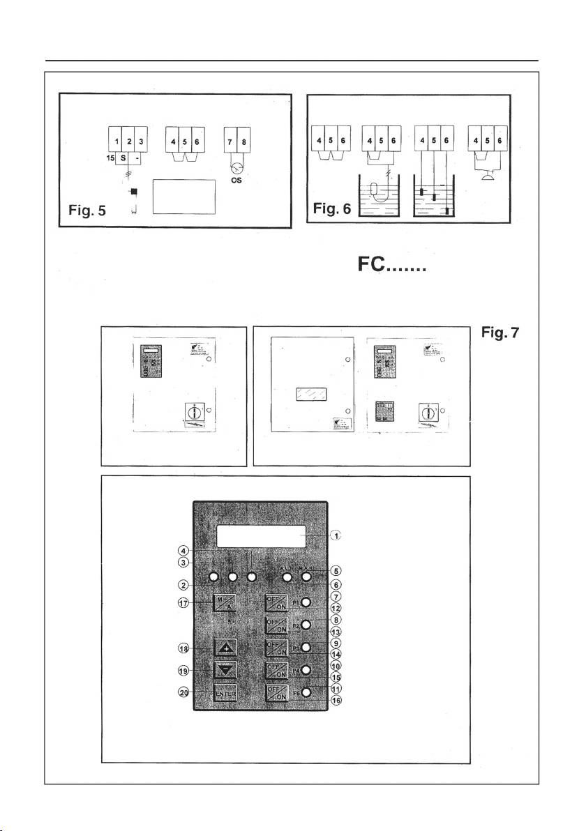
Chap.5 – Electric connection
See fig.3-4-5 and other schemes reported on the switchboard
GB

14
WARNING Before connecting the powersupplycableto the control board, check
that it has sufficient dimensions to support the maximum voltage
requiredbygrouppumps.
WARNING The connection of the distribution boards to the power grid must be
doneaccordingtoindicationsreported ontheelectricconnectionscheme
situated in the control board.
DANGER
Risk of electrical
discharge
Thesubstitutionofelectricandelectroniccomponentsmusttobedone
by a skilled staff.
Protection against the dry-operation of the motor pumps (See fig.6)
On the switchboard it is possible to connect a device for control of the level into the tank. (Our groups are delivered
with jumped terminals 4-5-6)
WARNING In this case the group is not protected against dry-operation. It is
therefore necessary to remove the electric jumpers and to connect
them to the control device chosen as follows:
1) float switch
The float must be installed in the tank and connected thanks to two wires to the special terminals on the control board.
2) electronic control with probes
The three probes should be specially placed in the first collection deposit and should be then connected to terminals
inside the board. The COMMON probe must be installed at the lowest level in the tank and anyway always at a level
lower than the minimum level probe (LOW) that prevents from the working of the pilot pump when water descends
below this level. The maximum level probe (HIGH) allows again the working of the pilot pump when the water reaches
this level.
3) Inverted minimal pressure sensor
In the case where the group is fed by a water duct under pressure (for example municipal water system), it is
necessary to install a minimal pressure sensor which prevents from the working of the group if the pressure in the
duct descends below the preset value.
Chap.6 – Starting up
See fig.3-4-5-6-7-8 and diagrams in the distribution board.
Control of the direction of rotation of the pump with inverter drive.
Once all the hydraulic and electric connections have been done for the hydraulic priming of the pumps and collectors,
proceed as follows:
- close all the valves of the distribution system
- open all the valves of the group, included those of the membrane ways
- control the closing of the distribution board hatch
- place the power supply disconnector on I (ON)
DANGER
Risk of electrical
discharge
Warning: from this moment any operations on pump ducts, pressure
transducer, pressure sensor, etc. must be done after having cut the
voltage off from the distribution board.
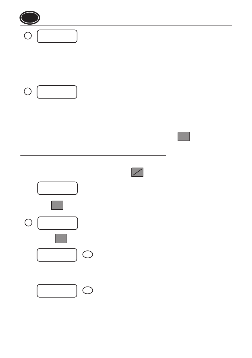
The following message (1) will be displayed
- a small bell will give out a set of beeps
- the green LED (2) will lit
Push the key until the following message is displayed
NOCCHI PUMPS
Bar 05.0
LINEA
M
A
GB
15
Control of pump priming (see Fig. 9).
The installation is prepared for MANUAL working
Push key (2) : n.1 pump will enter in function; push again the same key to stop the pump and to control
the sense of rotation of pump n.2 pump therefore the one of all other.
In the case where pumps would not turn all in the same sense, before proceeding to the correction check sense
of rotation of pumps directly fed (and no from an inverter).
Check the sense of rotation of pumps directly started
With the installation and the switchboard set for manual working, press key (12)
Pump n.1 will enter in function controlled by the inverter and, while maintaining it in operation, start pump 2 by pressing
the key (13). Premere nuovamente lo stesso e controllare il senso di rotazione della pompa n. 2.
Do the same operation on all other pumps, always with pump n.1 in operation. Stop pump n.1; enable pump n.2 as
first pump and check the sense of rotation of pump n.1.
- if pumps, either fed by an inverter or fed directly, have an inverted sense of rotation, proceed as follows:
DANGER
Risk of electrical
discharge.
Cutoffthegeneralvoltageandreversetwophasesofthepowersupply
cable of the switchboard.
- If on the contrary the sense of rotation of the pumps is inverted only when fed by inverter, proceed as follows:
DANGER
Risk of electrical
discharge.
Cutthe general voltage and reverse two phasesofpower supply cable
on the inverter (outlet terminal of the inverter)
WARNING The inversion of power phases of the inverter does not produce any
effect on the sense of rotation of the pumps.
- if one or several pumps supplied by the inverter do not have the same sense of rotation, proceed as follows:
DANGER
Risk of electrical
discharge.
Cut the general voltage off and reverse two drivers on power supply
leads on the inverter contactor of the pump in question.
- if one or some of the pumps directly fed have a reversed sense of rotation, proceed as follows:
DANGER
Risk of electrical
discharge.
Cut the general voltage off and reverse two leads on power supply
terminals of the contactor (or of direct contactor) of the pump in
question.
WARNING WARNING: before proceeding to control the priming of the pump,
checkthattheirmaximumpressure,reportedonthesamepumpplate,
is compatible with the pressure supported by the installation and by
facilities and that the possible safety valves have an intervention
value higher than the one of the maximum pump pressure.
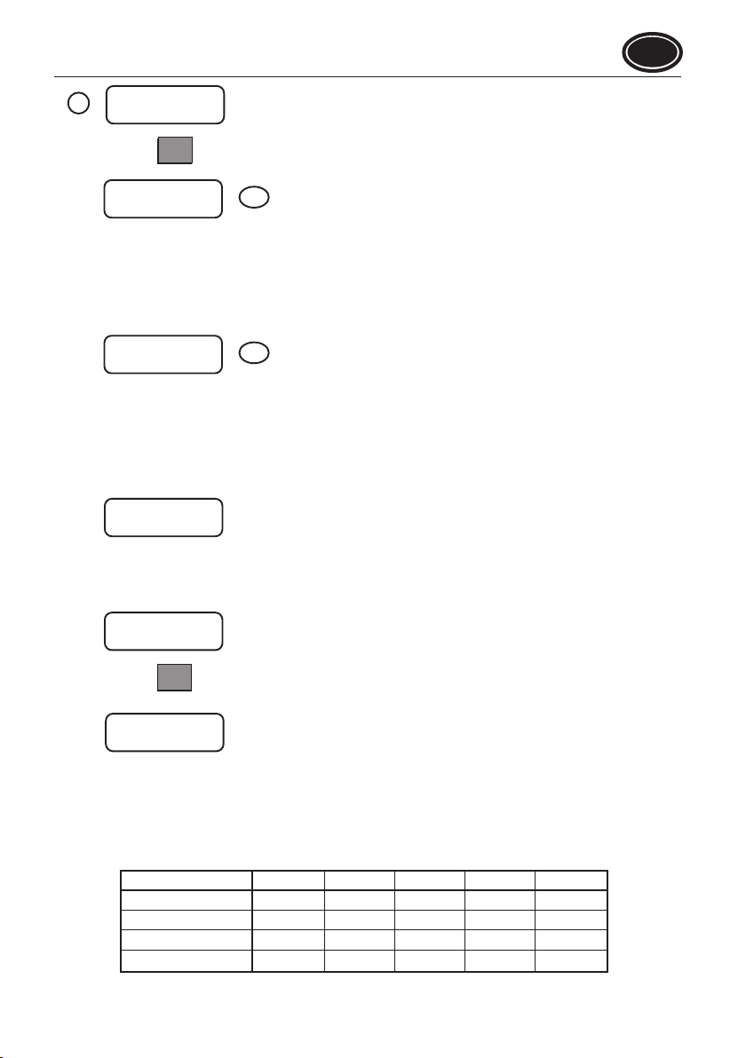
By keeping closed all collecting valves
DANGER
Risk of electrical
discharge.
Acting on the main switch, cut voltage off on switchboard, open the
shutterandpositionn.1switchon TEST and all others on EXCLUSION.
MANUAL FUNCTION
Bar 05.0
OFF
ON P1
OFF
ON P1
OFF
ON P2
GB
16
Close the board and give voltage; pump n.1 pump will enter in function, control that network pressure reaches the
maximum value. In the contrary case perform again the operations of replenishment of the aspiration collector until
the body of the pump. Repeat the operation on all pumps of the group.
Automatic starting up of the group (see fig.7-8).
After having put under pressure groups while manipulating the pump by hand, cut voltage off switchboard by
positioning the main switch on 0 (OFF).
Wait some seconds and send current to the switchboard: the green LED will lit and the small bell will give out
some beeps. The following message will be displayed:
The green LED will lit.
From this moment the groups will function automatically according to water flow withdrawn by the user.
Modification of the working pressure (see fig.7-8)
To change the value of the working pressure, maintain closed all drawings, rotate the main switch of the switchboard
on I (ON), press key (17) until the red LED will lit (manual working).
M
A
AUT
NOCCHI PUMPS
Bar 05.0
LINEA
WARNING WARNING: in all examples that follow (pressure, time, YES/NO etc…)
XXletterscanbeascribed or to indicative values (eg: 0.5 bar).Actually,
the parameters wished by the user shall be entered.
The following message will be displayed:
MANUAL FUNCTION
Bar 05.0
PROGR MENU.
INVERTER
THRESHOLD
Push the key (20) until the following message will be displayed:
SET POINT
Bar 05.0
Corresponding to the pressure value that the group will maintain in the delivery collector.
By using the combination of keys set the pressure parameter at the value desired.
At the end of the operation the following message will be displayed:
ENTER
STOP THRESHOLD
Bar 05.0
Corresponding to the pressure value of the last pump. Normally is set to a value of 0.5 bar at the SET POINT
pressure.
By using the combination of keys set the pressure parameter at the value desired.
At the end of the operation the following message will be displayed:
PROGR. MENU
TEMP. KICK STOP
ENTER
+-
ENTER
+-
MAN
GB

17
To exit from the programming mode press several times key (19)
PROGR. MENU
TEMP. KICK STOP
PROGR. MENU
INVERSION
PROGR. MENU
EXIT
MANUAL FUNCTION
Bar 10.0
NOCCHI PUMPS
Bar 05.0
-
--
- -
M
A
By pressing key (17) the unit will begin to function in AUTOMATIC
Chap.7–Change configuration and operational parameters
See fig.7-8
The program includes two menus:
1) Configuration menu of the machine and authorization to access calibration menu
2) Menu for the regulating of the working and calibration parameters
1) Configuration and access parameters of the machine and calibration menu
To access the menu, the board must be fed and set for the MANUAL working of the pump.
Check that all drawings are tightly closed and that the water distribution network is cut. Bring the general switch of
the switchboard to position I (ON). While the small bell gives out some beeps, press the key until the following
message will be displayed:
M
A
MANUAL FUNCTION
Bar 05.0
Press key (20) for about 10” up to when the following message will be displayed:
ENTER
- Line n. 1 - NUMBER OF PUMPS
By acting on keys it is possible to change the number of pumps controlled by the program.
Minimum 2 pumps
Maximum 5 pumps
- Line N.2 - SYSTEM STABILITY
This parameter determines a start-up delay time of pumps 3–4–5 which is added to the one set as start in menus 8
Minimum value 0
Maximum value 4
SYSTEM STABILITY – Time schedule in tenth of seconds (1/10”)
Set value
Pump 3
Pump 4
Pump 5
0
7
6
5
1
8
7
6
2
9
8
7
3
10
9
8
4
11
10
9
ENTER
+-
NUMBER OF PUMPS 5
STAB. SYSTEM 4
3
GB
18
- Line n.1 TRANSLATOR
Non modifiable description
- Line n.2 VALUE MAXIMUM BAR XX
The maximum value of the pressure transducer must be entered. Normally in our standard groups a transducer 0-5V
0-10 bar is used, therefore value 10 must be entered for this transducer.
TRANSDUCER
VALUE MAX Bar 10
4
MENU ACCESS
TOTALYES/NO
5
- N.1 line ACCESS MENU
Description non modifiable
- N.2 line TOTAL XX
YES permits to access menus 8–9–10
NO disable access to menus 8–9–10
Menu 6 regulating of operational parameters is accessed to by pressing key (20).
2) Menu for regulating operational and calibration parameters
The access to this menu is direct from configuration menu 1, otherwise proceed as follows:
check that all drawings are closed or that the water distribution network is cut. Bring the main switch to position I (ON).
While the small bell gives out some beeps, press the key, until the following message will be displayed:
M
A
MANUAL FUNCTION
Bar 05.0
ENTER
Press key (20) for about 2” until the following message will be displayed: appears the menu
ENTER
PROG MENU.
THRESHOLD
INVERTERS
6
Press key (20) ENTER
SET POINT
Bar 05.0 6a
- Line n.1 SET POINT
Indicates pressure value of the group
Following option
STOP THRESHOLD
Bar 05.0 6b
Line n.1 STOP THRESHOLD
- Indicates pressure stop value of the pump controlled by the inverter.
This function makes it possible to load membrane vessel to value superior than the one of the regulation pressure,
so as to allow a higher reserve of pressurized water and therefore a longer detention time.
GB
19
MENU PROGR.
TEMP. KICK STOP
7
Press key (20) ENTER
K.S DELAY.
10
05 7a
KS identifies the function inserted for stopping the pump controlled by the inverter. At time intervals corresponding
to the KS value established, the inverter feeds the pump at the maximum frequency (50 Hz) during the time set in
menu 7b - length KS.
Line n.1 DELAY KICK STOP
minimum interval 0 seconds (disabled)
maximum interval 99 minutes and 99 seconds.
KS LENGTH
05 /10 7b
- Line n.1 LENGTH KICK STOP
Minimum 0/10 seconds
Maximum 99/10 seconds
If during this period the pressure of installation reaches the value set in point 6b STOP THRESHOLD, the pump stops,
otherwise the modulation starts again.
If at option 5, NO has been inserted, the menu next is:
PROGR. MENU
EXIT
Which makes it possible to exit the programming.
Vice versa, if YES is entered, the following option is displayed
PROGR. MENU
DIRECT THRESHOLDS
Press key (20) ENTER
Bar PO: 2
Max04.2 Min03.7
For every pump successive to the first, it is possible to establish the pressure value appropriate for startup (Min.)
and for stop (Max.). The minimum pressure must be lower than the value ascribed to the SET POINT. The maximum
pressure must be higher than SET POINT value and lower or equal to the STOP THRESHOLD VALUE. The minimum
pressure ascribed to a pumps must be lower than the maximum one. The values ascribed to each pump are
interdependent and, except in particular needs of the plant, they can be the same for all pumps directly operated.
Example
STOP THRESHOLD
MAX PRESSURE
SET POINT
MIN PRESSURE
5.5
5,0
5,3
4,7
5,3
4,7
5,3
4,7
5,3
4,7
BAR PUMP 2 PUMP 3 PUMP 4 PUMP 5
GB

20
Note
The number of pumps that do not compose the group has no connection with the numbering used by the
microprocessorprogram.Infacttheprogramlogicconsiders as pump 1 the one that leaves first; pump 2 the one
that leaves for second and so on. The choice of the pump that leaves first (that can be n.3 or n.4 or n.5 or n.2 or
n.1) is carried out by the section of the program that manages the logic of inversions and commands.
PROG MENU.
DIRECT TEMP.
9
By press key (20) the following option is displayed:
ENTER
P.2 TEMPORIZATION
START 8 STOP 0 9a
- Line n.1 TEMPORIZATION P.2
Description non modifiable
- Line n.2 START XX
Indicates delay time, in seconds, for starting the second pumps in the presence of suitable pressostatic conditions
for startup.
Minimum 0 tenth of seconds.
Maximum 99 tenth of seconds.
- Line n.2 STOP XX
Indicates delay time, in seconds, for stopping the second pumps in the presence of suitable pressostatic conditions
for stoppage.
Minimum 0 tenth of seconds.
Maximum 99 tenth of seconds.
Follows the insertion of START and STOP parameters of the other pumps.
PROGR. MENU
INVERSION
10
By pressing key (20) the following option will be displayed:
ENTER
- Line n.1 CYCLIC BLOCKAGE XX
YES The inverter is associated to the pumps indicated in the second line.
CYCLIC BLOCK = YES
BLOCK OF PUMP 3 10a1
BL. CICLICO NO
CONTR.ESTERNO NO 10a2
- Line n.1 CYCLIC BLOCKAGE XX
NO
- Line n.2 EXTERNAL CONTR. (external control)
NO
The inverter is moved on the different pumps according to the logic of the cyclic inversion of the program at the end
of each working cycle.
If
- Line n. 2 EXTERNAL CONTROL
YES
The inverter is moved on the various pumps according to the cyclic inversion logics of the program at the successive
starting up after the closing of an external contact (for example: timer) or after the closure of an external contact
(example: daily timer). In this case the change of pump under inverter occurs after the first pause (the external
contact must be of short length and in any cases opened before the operational pause of the group).
GB
21
Cyclic inversion logics: at every beginning of the working cycle, the pump which has been last started is enabled
first. During the working of the group the pumps controlled directly are stopped in reverse order respect to the
one start up order.
Example: GROUP WITH 4 PUMPS
First pump started up controlled by the inverter of pumps 2
Second pump started up direct control of pump 3
Third pump started updirect control of pump 4
If the drawing is reduced, pump 3 is the first to stop, then pump 4
After the stop of all the pumps:
First pump started up controlled by the inverter of pumps 3
Second pump started up direct control of pump 1
Third pump started up direct control of pump 2
PROGR. MENU
EXIT
11
By pressing key (20) the system returns to MANUAL WORKING - red LED lit.
By pressing key (17) he green LED (6) s lit and the system begins to function automatically.
ENTER
MAN
M
A
AUT
Chap.8 – Failures
In case of system failure , the following messages can be displayed on the control board:
STOP FOR
LOW WATER LEVEL
A1
SYSTEM INVERTER
BLOCKED - RESET
A2
TEMP. P 3 4
Bar 04.6
A3
Explanation of messages (see fig.6)
1) Lack of water in withdrawal tank
The level control signals the lack of water in the withdrawal tank, or low pressure in the feed duct(aqueduct). At the
same time the red LED - BLOCKAGE LEVEL shall be lit. The same thing occurs in case of false contacts or absence
of level control if the relative terminal have not been short-circuited.
2) Blockage inverter
The inverter is blocked. The reason of the blockage is indicated on inverter display whose manual gives detail of the
position intervened. If the reason is accidental: momentary overcharge of the motor pump (example excessive
request of water), or electric too high or too low voltage, by pushing the RESET key situated on the inverter keyboard,
the system be reset. Otherwise cut the voltage off the switchboard for a few seconds and connect it again. In case
of failure, repeat the operation a second time.
If the blockage persists, it is possible to disable the inverter following the instructions reported in the following
chapter.
3) Thermal blockage
In case one the thermal relays protecting against overcharge or lack of power supply of the motor operating directly
(not controlled by the inverter) is tripped, in addition of the message on the display, the red LED (4) ANOMALY is lit
(the same of INVERTER BLOCKAGE). In this case the programs automatically excludes the pump or pumps that
generated the event and the group operates regularly, even if with a reduced rating. In order to reset, after having
verified the accidental origin of the overcharge, press the resetting lever situated on the thermal relays concerned.
GB

22
Chap.9–Exclusion of the inverter
In case of breakdown of the inverter, while waiting for the appropriated repair intervention, the group can operates
automatically or manually:
1) Automatic operation
The motor pumps are operated by an SFC card on pressure levels.
In this case it is necessary to cut the voltage off the switchboard and open the protective fuse-holder of the inverter
(see fig.3). It is therefore necessary to increase the value of STOP THRESHOLD following the indications reported
in chap.6 – starting up in point Modification of the working pressure established. The value of SET POINT
represents the startup pressure of the first pump. The one of STOP THRESHOLD indicates the value of stop pressure
of the last pump. The difference between these values must be of at least 1 bar.
Example
SET POINT 5.0 bar
STOP THRESHOLD 6,. bar
If tanks under pressure connected to the delivery collector of the group have a sufficient volume, the installation will
get back in function in the pressure range established (one of pumps, the one that should have been started up
controlled by the inverter will remain in stop). If one observes an abnormal operation (frequent starts up and stops
of pumps) it will be necessary to modify the pressure values established for every pump as described in point 2) of
Chap.7.
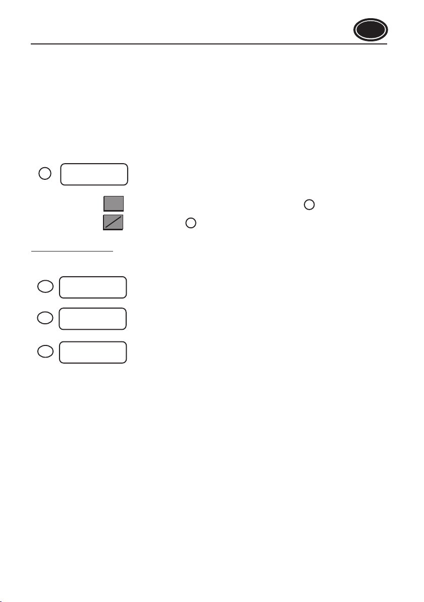
2) Manual working (see fig.9)
Theselectorssituated insidethe switchboardmakesit possibletooperate allpumps withexclusionof theinverter,
theSFC keyboard and thecard YES. If the selectoris in vertical position(EXCLUSION: the related pumpcannot
operates).
WARNING WARNING:inthiscasethe pumps can operate only if thewaterispumped
bythe user.Theworking of pumpswithoutpumpingmay cause damageto
pumpsandthegroup.
GB

Electropump
Float valve
On-off valve
Check valve
Standing valve with
filter
Level control
electrode
Level switch
Gauge - Vacuum
gauge
Hydraulic circuit
breaker
Flexible coupling
SYMBOLS USED AUTOCLAVE WITH
MEMBRANE DIAGRAM
USER
ELECTRIC
POWER SUPPLY
ELECTRIC
POWER SUPPLY
ELECTRIC
POWER SUPPLY
FC 20/ GROUP...
2 PUMPS MODULATED IN SPEED
FC 30/ GROUP...
3 PUMPS MODULATED IN SPEED
PRESSURE GROUP FC.40/..
4 PUMPS MODULATED IN SPEED
UNDERGROUND TANK WITH
ONE ONLY SUCTION
UNDERGROUND TANK WITH
INDEPENDENT SUCTION EXTERNAL TANK PRESSURE
DUCT
TYPICAL DIAGRAMS OF INSTALLATION
SERIES GROUPS
89
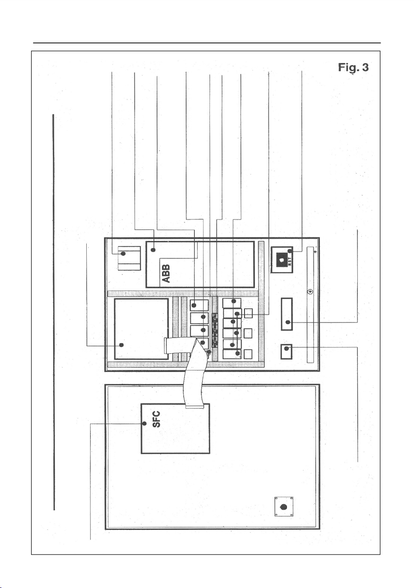
INTERNAL ARRANGMENT OF THE ELECTRIC BOARD COMPONENTS
FREQUENCY – CHANGER
CARD INTERFACE CARD
AUXILIARY DEVICE TRANSFORMER
INVERTER
FUSE CARRIER INVERTER
FUSE CARRIER DIRECT PUMPS
FUSE CARRIER AUXILIARY DEVICE
AUT – 0 – TEST SELECTOR
INVERTER PUMPS CONTACTOR
DIRECT PUMPS CONTACTOR
MAIN SWITCH
(ELECTRIC POWER SUPPLY)
ELECTROPUMPS
TERMINAL BOARD
EXTERNAL DEVICES
TERMINAL BOARD
SI
90

FREQUENCY CARD - CHANGER
WITH KEYBOARD
INVERTER INTERFACE CARD
PRESSURE
SENSOR
INVERTER
REMOVE THE
JUMPERS AND
CONNECT THE
CONTROL OF
SELECTED LEVEL
LEVEL CONTROL
TIMER FOR
TIMED
EXCHANGE
(OPTIONAL)
TERMINAL
BOARD FOR
POSSIBLE
PRESSURE
SWITCHS
(CHECK
AUTOCLAVE
VOLUME)
TERMINAL BOARD DEVICES OUTSIDE ELECTRIC BOARD
ELECTRIC
POWER SUPPLY
380 V 50 Hz
ENGINE VARIABLE
SPEED POWER
SUPPLY LINE
ELECTRONIC CARDS - INVERTER - EXTERNAL DEVICES TERMINAL
BOARD INTERCONNECTION DIAGRAM
Free
Free
High
Low
91
TERMINAL BOARD DEVICES OUTSIDE ELECTRIC BOARD LEVEL CONTROL CONNECTION
PRESSURE
SENSOR
REMOVE THE
JUMPERS AND
CONNECT THE
CONTROL OF
SELECTED LEVEL
LEVEL CONTROL
TIMER FOR
TIMED
EXCHANGE
(OPTIONAL)
NO CONTROL FLOAT ELECTROPROBE
MINIMUM
PRESSURE
SWITCH
HIGH
LOW
COMMON
PRESSURE GROUPS
FREQUENCY CHANGER MODEL
ELECTRIC BOARDS AND ELECTRONIC CARD KEYBOARD
CONTROL BOARD WITH
INVERTER INVERTER BOARD CONTROL BOARD
ELECTRONIC CARD KEYBOARD
Red indicator light anomaly
Red indicator light
thermal trip
Green indicator light line
present
Selection push button
Man / Aut
Menu increment push
button
Menu decrement push
button
Menu access and
confermation push button
2 lines 16 characters display
Red indicator light manual operation
Green indicator light automatic operation
Green indicator light no. 1 pump operation
Manual operation push button pump no. 1
Green indicator light no. 2 pump operation
Manual operation push button pump no. 2
Green indicator light no. 3 pump operation
Manual operation push button pump no. 3
Green indicator light no. 4 pump operation
Manual operation push button pump no. 5
Green indicator light no. 5 pump operation
Manual operation push button pump no. 5
LINEA
BLOCCO
LIVELLO ANOMALIA
92

NOCCHI PUMPS
Bar 05.0
MANUAL FUNCTION
Bar 05.0
NUMBER OF PUMPS 5
STAB. SYSTEM 4
TRANSDUCER
VALUE MAX Bar 10
MENU ACCESS
TOTAL YES/NO
PROG. MENU
THRESHOLD INVERTERS
MENU PROGR.
TEMP. KICK STOP
PROGR. MENU
DIRECT THRESHOLDS
SET POINT
Bar 05.0
STOP THRESHOLD
BAR 05.0
K.S DALAY.
10 05
KS LENGTH
05/10
Bar PO:2
Max 04.2 Min 03.7
Bar PO:3
Max 04.2 Min 03.7
Bar PO:4
Max 04.2 Min 03.7
Bar PO:5
Max 04.2 Min 03.7
P.2 TEMPORIZATION
START 8 STOP 0
P.3 TEMPORIZATION
START 3 STOP 0
P.4 TEMPORIZATION
START 3 STOP 0
P.5 TEMPORIZATION
START 1 STOP 0
PROGR. MENU
DIRECT TEMP.
PROGR. MENU
INVERSION
CYCLIC BLOCK = YES
BLOCK OF PUMP 3
CYCLIC BLOCK = NO
EXTERN.CONTR. YES
PROGR. MENU
EXIT
MANUAL FUNCTION
Bar 10.0
NOCCHI PUMPS
Bar 05.0
STOP FOR LOW
WATER LEVEL
SYSTEM INVERTER
BLOCKED - RESET
TEMP. P 3 4
Bar 04.6
FREQUENCY CHANGER DIAGRAM
FLOW DIAGRAM OF THE MENUS AND FAULT MESSAGES
FAULT MESSAGES
BY KEEPING PRESSED FOR 10” BY KEEPING PRESSED FOR 2”
93

PUMP No. 1 PUMP No. 2
PUMP No. 1 PUMP No. 2 PUMP No. 3
CUT-OUT
DIRECT
START
TEST
AUTOMATIC
CARD
CUT-OUT
DIRECT
START
TEST
AUTOMATIC
CARD
CUT-OUT
DIRECT
START
TEST
AUTOMATIC
CARD
CUT-OUT
DIRECT
START
TEST
AUTOMATIC
CARD
CUT-OUT
DIRECT
START
TEST
AUTOMATIC
CARD
94

95
I
This manual suits for next models
1
Table of contents
Other Nocchi Water Pump manuals


Popular Water Pump manuals by other brands


North Ridge Pumps
North Ridge Pumps NOVA ROTORS DIAMOND DX Series OPERATING, USE AND MAINTENANCE INSTRUCTIONS

Masterflex
Masterflex I/P 73 operating manual

GORMAN-RUPP
GORMAN-RUPP SM SERIES manual

Milton Roy
Milton Roy MAXROY Series Actuator Capacity Control Manual

CLAS
CLAS OH 0014 manual

Teral
Teral NSVM Series Installation & operating manual


