manuals.online logo
Brands
  1. Home
  2. •
  3. Brands
  4. •
  5. NOCH
  6. •
  7. Toy
  8. •
  9. NOCH 88400 User manual

NOCH 88400 User manual

88400 ∙ 88405 Betriebsanleitung für Modellbahnkoffer
Instruction Manual for Model Railway Briefcase
„Berchtesgaden“ & „Garmisch“
·Fahrfertige Modellbahnanlage im Aluprofil-Koffer
(Außenmaße Koffer: 79,5 x 54,5 cm, 16 cm hoch)
·Gelände aus Struktur-Hartschaum, komplett ausgeschmückt
·Zwei Bahnstromkreise, fahrfertig montiert
·Steuerpult mit zwei Fahrreglern
·Vier beleuchtete Gebäude. Beim Modell „Garmisch“ zusätzlich ein
beleuchteter Weihnachtsbaum.
·Anschluss erfolgt über beiliegendes Steckernetzgerät
(Eingang: 100 – 240 V, Ausgang: 12 V Gleichstrom, 1 A)
·Hinweis Zugzusammenstellung: Wegen der engen Radien sollten
die eingesetzten Waggons nicht länger als 9 cm sein
Produktdetails
·Ready-to-run model railway layout in an aluminium briefcase
(outer dimensions briefcase: 79.5 x 54.5 cm, 16 cm high)
·Structured hard foam layout, completely decorated
·Two train circuits, ready assembled
·Control box with 2 train controllers
·Four illuminated houses. The model „Garmisch“ furthermore
includes an illuminated Christmas Tree.
·Connection is made by included power supply
(input: 100 – 240 V, output: 12 V DC, 1 A)
·Note for train combination: Please make sure that wagons
are not longer than 9 cm because of the tight radius
Product Details
Inbetriebnahme Ihres Modellbahn-Koffers
Ein- und Ausschalten der Anlage
Schließen Sie das beiliegende Netzteil an, indem Sie es zuerst mit dem
Netzteilanschluss an der Kofferanlage verbinden und anschließend in
eine Steckdose (Eingangsspannung 100 – 240 V) einstecken. Die Anlage
ist nun betriebsbereit! Modellbauartikel, kein Spielzeug!
Mit dem linken schwarzen Fahrregler steuern Sie die Geschwindigkeit
und Fahrtrichtung der Lokomotiven im Außenkreis 1. Der Fahrregler
hat eine fühlbare Mittelstellung.
Mit dem rechten schwarzen Fahrregler steuern Sie die Geschwindigkeit
und Fahrtrichtung der Lokomotiven im Innenkreis 2. Der Fahrregler
hat eine fühlbare Mittelstellung.
Der Innen- und Außenkreis Ihrer Anlage wird von zwei Fahrreglern
auf unabhängigen Stromkreisen gesteuert. Um beim Fahren aus
einem Kreis in den anderen ein elektrisches Überbrücken der beiden
Stromkreise durch die Lokomotive und folgend einen Kurzschluss
zu vermeiden, können die beiden Gleiskreise zusammengeschaltet
werden. Alle Triebfahrzeuge werden dann über den Fahrregler des
Außenkreises 1 gesteuert. Bitte beachten Sie, dass in diesem
Modus keine unabhängige Steuerung von zwei Lokomotiven auf den
beiden Gleiskreisen mehr möglich ist, bis Sie in den Normalmodus
zurückkehren.
Drücken Sie zum Aktivieren der Übergangsfahrt den Taster 1+2!
Durch erneutes Drücken wechseln Sie zur Einzelsteuerung zurück.
Hinweis: Ein Gleiskreiswechsel ist auch dann möglich, wenn an beiden
Gleiskreisen dasselbe Potential – gleiche Fahrtrichtung – anliegt.
Die Lokomotive kann die Kreise wechseln und ist mit den jeweiligen
Geschwindigkeitsreglern steuerbar.
Achtung: Dies ist auch bei einem Betrieb mit zwei Lokomotiven möglich
(Unfallgefahr!).
Das Stadtlicht können Sie mit dem Taster ein- bzw. ausschalten.
Sollte an der Anlage ein Kurzschluss anliegen, dann schaltet die
Elektronik den entsprechenden Stromkreis stromlos. Sobald der
Kurzschluss beseitigt wurde, lässt die Elektronik den Strom wieder zum
Gleis. (Kurzschlusserkennung!)
Operating Your Model Railway Briefcase
Switching the Layout On and Off
Connect the enclosed adapter by first connecting it to the power supply
port on the briefcase layout and then plugging it into a socket
(100 – 240 V input voltage). The layout is now ready for operation!
Modelling product, not a toy!
With the black controller on the left, you can control the locomotives’
speed and direction of travel on the outer circuit, 1. The controller
has a tactile middle position.
With the black controller on the right, you can control the locomotives’
speed and direction of travel on the inner circuit, 2. The controller
has a tactile middle position.
The inner and outer circuits on your layout are controlled by two
controllers on independent electric circuits. To avoid an electrical
bridging of the two circuits by the locomotive and a subsequent short
circuit when driving from one circuit to the other, the two track circuits
can be interconnected. All traction units are then controlled via the
controller for the outer circuit, 1. Please be aware that in this mode
it is no longer possible to control two locomotives independently on the
two track circuits until you return to normal mode.
Press the 1+2 button to activate the transition drive! Press it again
to switch back to single control.
Note: changing track circuits is also possible if the same potential –
the same direction of travel – is applied to both circuits.
The locomotive can change circuits and can be controlled with the
respective speed controllers.
Warning: this is also possible when operating two locomotives
(accident risk!).
You can switch the city light on or off with the button.
If there is a short circuit on the layout, the electronics shut off the
corresponding electric circuit. As soon as the short circuit has been
removed, the electronics allow the current to flow back to the track.
(Short-circuit detection!)
Mise en marche de votre réseau en malette
Mise en marche et arrêt du réseau
Branchez le bloc d‘alimentation fourni en le reliant d‘abord à la prise
d‘alimentation sur la valise du réseau et en le branchant ensuite sur
une prise de courant ( tension d‘entrée 100 – 240 V ). Le réseau est
maintenant prêt à fonctionner ! Article de modélisme, pas de jouet !
A gauche, le régulateur noir vous permet de commander la vitesse
et le sens de marche des locomotives du circuit de voie extérieur.
1 Le régulateur a une position médiane perceptible.
A droite, le régulateur noir vous permet de commander la vitesse
et le sens de marche des locomotives du circuit de voie intérieur.
2 Le régulateur a une position médiane perceptible.
Les circuits de voie intérieur et extérieur de votre réseau sont
indépendants et commandés par deux régulateurs de vitesse. Pour éviter
un pontage électrique causé par la locomotive lors du passage d‘un
circuit à l‘autre, et par conséquent un court-circuit, les deux circuits
de voie peuvent être interconnectés. Toutes les locomotives sont alors
commandées par le régulateur du circuit de voie extérieur 1.
Veuillez noter que dans ce mode, il n‘est plus possible de commander
indépendamment deux locomotives sur les deux circuits de voie jusqu‘à
ce que vous reveniez au mode normal.
Pour activer le mode interconnecté, appuyez sur le bouton 1+2 ! En
appuyant à nouveau sur ce bouton, vous revenez au mode de commande
individuelle.
Remarque : un changement de circuit de voie est également possible
lorsque le même potentiel – même sens de marche – est appliqué
aux deux circuits de voie. La locomotive peut changer de circuit et est
pilotable avec les régulateurs correspondants.
Attention : ceci est également possible en cas d‘exploitation avec deux
locomotives. ( Risque d‘accident ! )
Les éclairages de la ville peuvent être allumés ou éteints à l‘aide du
bouton-poussoir .
Si un court-circuit se produit sur le réseau, l‘électronique met le circuit
de voie correspondant hors tension. Dès que le court-circuit est réparé,
l‘électronique laisse à nouveau passer le courant vers la voie. ( Détection
de court-circuit ! )
locomotief kan van ringen wisselen en is met de betreffende rijregelaar
aan te sturen.
LET OP: Dit is ook bij gebruik van twee locomotieven mogelijk (gevaar
voor botsing!).
De stadsverlichting kan met de knop worden in- en uitgeschakeld.
Is er op de modelspoorbaan een kortsluiting, dan schakelt de elektronica
de betreffende stroomkring uit. Zodra de kortsluiting is opgeheven, laat
de elektronica de stroom weer door naar de baan. (kortsluitherkenning!).
WEEE-Hinweis „Umweltgerecht entsorgen“
Produkte, die mit einem durchgestrichenen Mülleimer-Symbol
gekennzeichnet sind, dürfen am Ende ihrer Lebensdauer nicht über den
normalen Haushaltsabfall entsorgt werden, sondern müssen an einem
Sammelpunkt für das Recycling von elektrischen und elektronischen
Geräten abgegeben werden. Wir sind bei der Stiftung EAR (Elektro-
Alt-Geräte Register) registriert. Unsere Registrierungsnummer lautet:
DE95117429.
Elektro- und Elektronikgeräte (EEE) und Elektro- und Elektronikaltgeräte
(Waste Electrical and Electronic Equipment, WEEE) können kostenfrei
zur Rücknahme zum stationären Handel oder zum Hersteller
geliefert werden.
Das Symbol auf dem Produkt, der Gebrauchsanleitung oder der
Verpackung weist darauf hin. Die Wertstoffe sind gemäß ihrer
Kennzeichnung wiederverwertbar. Mit der Wiederverwendung, der
stofflichen Verwertung oder anderen Formen der Verwertung von
Altgeräten leisten Sie einen wichtigen Beitrag zum Schutze unserer
Umwelt. Bitte erfragen Sie bei Ihrer Gemeindeverwaltung die zuständige
Entsorgungsstelle.
Beachten Sie die örtlichen Bestimmungen zur Abfallbeseitigung.
Beachten Sie die WEEE-Richtlinie in ihrer derzeit aktuellen Fassung.
Entnehmen Sie vor einer Verschrottung des Produkts ggf. enthaltene
Batterien oder Akkus.
WEEE Note „Dispose of environmentally friendly“
Products marked with a crossed-out garbage can symbol must not be
disposed of with other household waste at the end of their working life,
but must be taken to a collection point for the recycling of electrical
and electronic equipment. We are registered with the foundation EAR
(Elektro-Alt-Geräte Register). Our registration number is: DE95117429
Electrical and Electronic Equipment (EEE) and Waste Electrical and
Electronic Equipment (WEEE) can be delivered free of charge to the
stationary retailer or manufacturer for take-back.
The symbol on the product, the instructions for use or the packaging
indicates this. The recyclable materials are recyclable according to their
labeling. By reusing, recycling or otherwise recovering old equipment,
you are making an important contribution to protecting our environment.
Please ask your local authority for the responsible disposal point.
Observe the local regulations for waste disposal.
Observe the WEEE directive in its current version.
Before scrapping the product, remove any batteries or rechargeable
batteries it may contain.
Model building item, not a toy! Not suitable for children under 14 years!
Article de modélisme. Ceci n’est pas un jouet.
Articolo di modellismo, non è un giocattolo!
Artículo para modelismo ¡No es un juguete!
Artigo para modelismo. Este artigo não é um brinquedo!
Výrobek urĉený pro modeláře, nejedná se o hračku!
Modelbouwartikel, geen speelgoed!
Modellbyggarartikel, detta är inte en leksak!
Elektro- und Elektronikaltgeräte sowie
verbrauchte Batterien gehören nicht in den
Hausmüll, sondern müssen fachgerecht
entsorgt werden.
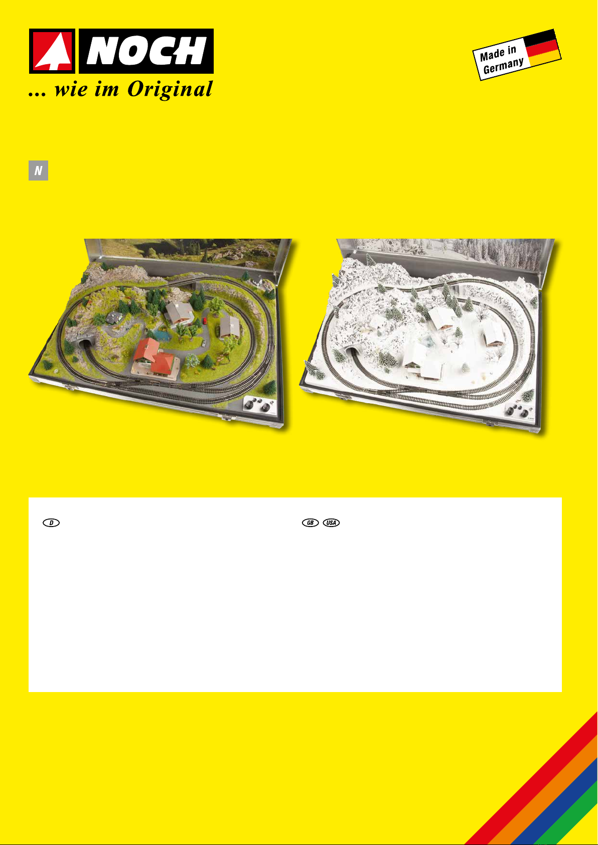
Puesta en marcha de su maqueta ferroviaria
en maletín
Encendido y apagado de la maqueta:
Conecte la fuente de alimentación adjunta conectándola primero a
la conexión de la fuente de alimentación en el sistema de maqueta
en maletín y luego enchufándola a una toma de corriente (tensión de
entrada 100 – 240 V). ¡El sistema ya está listo para funcionar! Artículo de
modelismo, no de juguete!
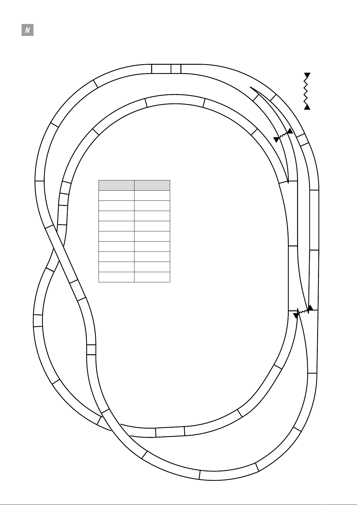
Con el regulador de velocidad de color negro situado a la izquierda controla
la velocidad y la dirección de la locomotora en el círculo exterior 1.
El mando de control de la velocidad tiene una posición central táctil.
Con el botón negro de control de velocidad de situado a la derecha se
controla la velocidad y la dirección de la locomotora en el círculo interior
2. El mando de control de la velocidad tiene una posición central táctil.
Los circuitos interiores y exteriores de su maqueta están controlados por
dos reguladores de velocidad en circuitos independientes.
Para evitar que al pasar la locomotora de un circuito al otro se ocasione
un bypass eléctrico (derivación) de los dos circuitos y, en consecuencia,
se produzca un cortocircuito, los dos circuitos de la vía pueden estar
conectados entre sí.
Todas las unidades de tracción se controlan a través del regulador de
velocidad del circuito exterior 1. Tenga en cuenta que en este modo,
ya no es posible el control independiente de dos locomotoras en los dos
circuitos de vía hasta que vuelva al modo normal.
¡Para activar el recorrido de transición, pulse el botón 1+2 ! Púlselo
de nuevo para volver al control individual.
Nota: También es posible un cambio de circuito de vía si se aplica el mismo
potencial – el mismo sentido de la marcha – a ambos circuitos de vía.
La locomotora puede cambiar de circuito y es controlada con los
respectivos reguladores de velocidad.
Atención: Esto también es posible cuando se opera con dos locomotoras
(¡peligro de accidente!).
Puede encender o apagar la luz de la ciudad con el interruptor .
Si se produce un cortocircuito en el sistema, el sistema electrónico
desconectará la alimentación del circuito correspondiente. En cuanto se
elimina el cortocircuito, la electrónica permite que la corriente vuelva a
fluir hacia la vía. (¡Detección de cortocircuitos!)
In gebruik nemen van de modelspoorkoffer
In- en uitschakelen van de modelspoorbaan
Sluit de bijgevoegde adapter aan, nadat de netaansluiting is verbonden
met de kofferbaan, op de contactdoos van het net (100 – 240 V).
De modelspoorbaan is nu bedrijfsgereed! Modelbouwartikel, geen
speelgoed!
Met de linker zwarte rijregelaar regelt u de snelheid en rijrichting van
de locomotieven in de buitenring 1. De regelaar heeft een voelbare
middeninstelling.
Met de rechter zwarte rijregelaar regelt u de snelheid en rijrichting van
de locomotieven in de binnenring 2. De regelaar heeft een voelbare
middeninstelling.
De binnen- en buitenring worden door twee rijregelaars onafhankelijk
van elkaar aangestuurd. Om een elektrische overbrugging van de beide
ringen door de locomotief en een daarop volgende kortsluiting bij het
rijden van de ene naar de andere ring te voorkomen kunnen de beide
railringen met elkaar verbonden worden. Alle locomotieven worden dan
door de rijregelaar van de buitenste ring 1 aangestuurd.
Let op: in deze mode is een onafhankelijke aansturing van twee
locomotieven op de beide ringen niet meer mogelijk, totdat wordt
teruggekeerd naar de normale mode. Druk op de knop om de overgang te
activeren 1+2! Door opnieuw op de knop te drukken wordt naar de
normale mode teruggekeerd.
Aanwijzing: een railring wijziging is ook mogelijk wanneer bij beide
railringen hetzelfde potentiaal aanwezig is en dezelfde rijrichting. De
954 954
914
914
957
914
914
954
03
904
904
912
912
912
912
912
912
91
2
912
912
914
914
904
09
912
912
912
912
912
16
16
09
914
914
16
912
912
912
912
912
912
07
09
03
03
Trennung* ∙Disconnection*
NOCH GmbH & Co. KG ∙ Lindauer Straße 49 ∙ D-88239 Wangen im Allgäu ∙ E-Mail: info@noch.de ∙ www.noch.de ∙ www.noch.com 02/ 2022
88400 ∙ 88405
Gleisplan Märklin® mini-club ∙ Track Plan Märklin® mini-club
Stück / Pieces Art.-Nr. / Ref.
314903
314904
114907
314909
20 14912
814914
314916
314954
114957
Hinweis:
Aus Platzgründen wurde die Vornummer 14 bzw.
149 teils weggelassen. So entspricht z. B. das
Gleis »912« der Art.-Nr. 14912 und das Gleis
»07« der Art.-Nr. 14907.
Wie viele der einzelnen Gleise benötigt werden,
entnehmen Sie der Tabelle.
Note:
Due to lack of space the pre-numbers 14 or 149
are partly omitted. For example the ref. »912«
means track ref. 14912 and »07« is track
ref. 14907.
The required quantity of the respective track is
listed in the table.

This manual suits for next models

1

Other NOCH Toy manuals

NOCH LASER CUT minis Water Lilies User manual

NOCH

NOCH LASER CUT minis Water Lilies User manual

NOCH 14635 User manual

NOCH

NOCH 14635 User manual

NOCH 14620 User manual

NOCH

NOCH 14620 User manual

NOCH 14345 User manual

NOCH

NOCH 14345 User manual

NOCH 14227 User manual

NOCH

NOCH 14227 User manual

NOCH 14678 User manual

NOCH

NOCH 14678 User manual

NOCH Mulled-Wine Stall User manual

NOCH

NOCH Mulled-Wine Stall User manual

NOCH 14260 User manual

NOCH

NOCH 14260 User manual

NOCH Small Footbridge User manual

NOCH

NOCH Small Footbridge User manual

NOCH 66310 User manual

NOCH

NOCH 66310 User manual

NOCH 14214 User manual

NOCH

NOCH 14214 User manual

NOCH 14221 User manual

NOCH

NOCH 14221 User manual

NOCH 14366 User manual

NOCH

NOCH 14366 User manual

NOCH 66412 User manual

NOCH

NOCH 66412 User manual

NOCH 88401 User manual

NOCH

NOCH 88401 User manual

NOCH 14244 User manual

NOCH

NOCH 14244 User manual

NOCH Sound Scene User manual

NOCH

NOCH Sound Scene User manual

NOCH 14479 User manual

NOCH

NOCH 14479 User manual

NOCH 14391 User manual

NOCH

NOCH 14391 User manual

NOCH 14306 User manual

NOCH

NOCH 14306 User manual

NOCH 67032 User manual

NOCH

NOCH 67032 User manual

NOCH 14365 User manual

NOCH

NOCH 14365 User manual

NOCH 14369 User manual

NOCH

NOCH 14369 User manual

NOCH 67042 User manual

NOCH

NOCH 67042 User manual

Popular Toy manuals by other brands

Eduard Zoom AH-1Z Assembly instructions

Eduard

Eduard Zoom AH-1Z Assembly instructions

MGA Entertainment READY2ROBOT quick start guide

MGA Entertainment

MGA Entertainment READY2ROBOT quick start guide

Robitronic protos instruction manual

Robitronic

Robitronic protos instruction manual

Flitework Extra 300LPX instructions

Flitework

Flitework Extra 300LPX instructions

Horizon Hobby E-flite Habu SS 50mm EDF instruction manual

Horizon Hobby

Horizon Hobby E-flite Habu SS 50mm EDF instruction manual

Eduard Su-25K Frogfoot interior Assembly instructions

Eduard

Eduard Su-25K Frogfoot interior Assembly instructions

Amdi PARTNER/STEPPER instruction sheet

Amdi

Amdi PARTNER/STEPPER instruction sheet

MD MXION SWD-ED user manual

MD

MD MXION SWD-ED user manual

Eduard 49 267 manual

Eduard

Eduard 49 267 manual

TILLIG TT BAHN 203875 manual

TILLIG TT BAHN

TILLIG TT BAHN 203875 manual

Eduard Zoom Spitfire Mk.VIII Assembly instructions

Eduard

Eduard Zoom Spitfire Mk.VIII Assembly instructions

LEXIBOOK RPB120MA instruction manual

LEXIBOOK

LEXIBOOK RPB120MA instruction manual

Jamara Car race Track Double Looping Instruction

Jamara

Jamara Car race Track Double Looping Instruction

Conrad 1932782 manual

Conrad

Conrad 1932782 manual

LEGO Technic 8417 Building instructions

LEGO

LEGO Technic 8417 Building instructions

Eduard FE 1277 quick start guide

Eduard

Eduard FE 1277 quick start guide

Clas Ohlson 31-5158 instruction manual

Clas Ohlson

Clas Ohlson 31-5158 instruction manual

BLOTZ B28-ME-010 quick start guide

BLOTZ

BLOTZ B28-ME-010 quick start guide

manuals.online logo
manuals.online logoBrands
  • About & Mission
  • Contact us
  • Privacy Policy
  • Terms and Conditions

Copyright 2025 Manuals.Online. All Rights Reserved.