NOHMI FDGJ103-D-X/XHT User manual

5mー100m
OPERATING MANUAL
Projected Beam Type Smoke Detector
Models FDGJ103/203-D-X/XHT
TN51541e-1
CAUTION Be sure to read this manual before use of this product. In addition,
carefully read and understand all the warning/cautions/notes in this
manual to use/operate this product.
● Please keep this operating manual in place so that it may be available at all
the times.
● Be sure to conduct the regular inspection and maintenance for this product.

INTRODUCTION
CONTENTS
Thank you for purchasing our projected beam type smoke detector. This detector
has passed various tests in accordance with the standards of the Japanese Fire
Service Law and is approved as the national type approval product.
Be sure to read this manual carefully before use of this product to properly
use/operate this product in case of fire. Please keep this operating manual in
place so that it may be available at all the times.
1. FEATURES OF THIS PRODUCT• • • • • • • • • • • • • • • • • • • • • • • • • •
2. BEFORE USE• • • • • • • • • • • • • • • • • • • • • • • • • • • • • • • • • • • • • • •
3. CAUTIONS FOR USE • • • • • • • • • • • • • • • • • • • • • • • • • • • • • • • • •
4. CAUTIONS ON INSTALLATION WORK AND OPERAION • • • • • • • •
5. ITEMS REQUIRED FOR INSTALLATION• • • • • • • • • • • • • • • • • • • •
6. NAME OF EACH PART • • • • • • • • • • • • • • • • • • • • • • • • • • • • • • • •
7. WORK FLOW• • • • • • • • • • • • • • • • • • • • • • • • • • • • • • • • • • • • • • •
8. CONNECTION WITH FIRE CONTROL PANEL• • • • • • • • • • • • • • • •
9. INSTALLATION/CONNECTION/SETTING • • • • • • • • • • • • • • • • • • •
10. CONNECTION OF HEATER (HEATER TYPE ONLY)• • • • • • • • • • •
11. LIGHT AXIS ADJUSTING METHOD• • • • • • • • • • • • • • • • • • • • • • •
12. LIGHT AXIS ADJUSTING METHOD (FLICKERING PATTERN)• • • •
13. TROUBLESHOOTING• • • • • • • • • • • • • • • • • • • • • • • • • • • • • • • •
14. REGULAR MAINTENANCE & INSPECTION • • • • • • • • • • • • • • • •
15. SPECIFICATIONS• • • • • • • • • • • • • • • • • • • • • • • • • • • • • • • • • • •
1
1
2
3
4
5
7
8
9
11
12
17
19
22
23

- 1 -
1. FEATURES OF THIS PRODUCT
2. BEFORE USE
WARNING
CAUTION
● Sensitivity Compensation Function to Keep Stable Function
: The detector sensitivity is automatically compensated and adjusted even in
case that the level of the light received by the light receiver is decreased due
to contamination on the detector lens surface.
● Light Axis Adjustment without Voltmeter (Tester)
: Light output can be checked by means of the light emitting pattern of the
indicator lamps, without using a voltmeter.
● Easy Installation
: This product can be installed as an unit with the assembled state by
changing the assembling Combination of the base, the cover and the body
depending on the installation site conditions.
● To use this product safely, this operating manual contains various cautions.
Before using this product, understand the following caution markings together
with the statements and read this manual. When using this product, be sure to
bring this manual at all times.
Mishandling may result in the user exposed to serious injuries or damage.
Failure to observe these guidelines may also cause serious damages to a part
of the fire protection function of the product.
Mishandling may result in the user injuries. Failure to observe these guidelines
may also have an adverse effect on the fire protection function of the product.
It is important to observe these guidelines at all times in order to effectively
utilize the fire protection functions over long-term use.
This mark shows a matter related to Danger, Warning or Caution.
■ CAUTION Markings
This mark shows an action to be taken or the instructions on
actions.
This mark shows the prohibition of actions.

- 2 -
3. CAUTIONS FOR USE
● Where it is directly exposed to rain or water.
● Where smoke or mist is usually generated.
● Where the light receiver is subjected to direct sunlight or strong
illumination light.
● Where the ambient temperature is lowered below -10°C or
exceeds 50°C.
● Where the mounting position of the detector is subjected to
vibration or strain. (Install the detector on a rigid position such as a
support/pillar of the main structure.)
● Where it is difficult to perform maintenance and inspection.(Space
of 50cm in vertical and horizontal directions (50cm each in
left/right/up/down directions) is required for surrounding of the
detector. In case that the ceiling height is 2.5 m or lower, pay
attention to the upper space. Example: If the ceiling height is
2.1m, the upper space is to be 42cm.)
● Where the light axis (between the light transmitter and receiver)
may be interrupted due to transportation of objects or a
transparent obstacle such as glass.
● In a place where a ball or a bar is usually used, such as
gymnasium, apply the protective cover (Model FZP014).
As this product is not of outdoor type, DO NOT install it in any of the following
places. (If installed, it may cause a malfunction or abnormal operation.)
Space for a screwdriver is required in the
above of the detector.
Prohi-
bition
Installation Standard :
The detector shall be installed so
that the height of the light axis
exceeds 80% of the ceiling
WARNING

- 3 -
4. CAUTIONS ON INSTALLATION WORK
AND OPERATION
● Be sure to arrange a secure scaffold.
● Make sure that nobody is located under the worker installing the
detector.
● Turn OFF the power supply of the fire control panel and remove
the battery provided in the panel as the auxiliary power. (Excl. the
case for light axis adjustment after installation work)
● Ensure that this product is not damaged due to drop, impact or
handling of a tool.
● DO NOT touch the front plate nor the lens. (If touched, the front
plate or the lens may contaminated, causing an adverse effect on
the detector function.)
● The Models FDGJ103/203-D-XHT are equipped with a heater.
As the heater becomes hot, NEVER touch. If touched, you may
get burnt.
(Position of heater Refer to 6. NAME OF EACH PART on
Page 6.)
● NEVER apply any vibration or impact/shock to the product,
disassemble/modify the product, or insert any foreign material into
the product, as these actions may cause a fault in the product.
● As this product is a component device of the automatic fire alarm
system stipulated in the Japanese Fire Service Law, do not use it
for any other applications.
When installing and operating this product, pay attention to the following matters.
Prohi-
bition
WARNING
INSTRUC-
TIONS

- 4 -
5. ITEMS REQUIRED FOR INSTALLATION
To install this product, the following items are used.
Arrange them according to the necessity.
No.
1
DESCRIPTION
Phillips type screwdriver For M4 and M5 screws
Test filter set (Model FXG012C)
REMARK
2
Battery connector for detector
test
If the auxiliary battery (for test) (24V,
with connector) is used, arrange it.
3
4
Solderless tool and terminals
(with heater type)
Auxiliary battery (for test)
(24V, with connector)
The light axis of this detector can be
adjusted with the auxiliary power
supply (Battery, 0.225AH to 3.5AH ).
In case of the detector with heater,
connection of the heater power is
made with solderless method.
(AWG22(0.3mm2) and AWG20
(0.5mm2) wires one each)
5

- 5 -
Light transmitter
Left :Power lamp
(Green)
Right:Test lamp
(Red)
6. NAME OF EACH PART
Cover Body fixing screwFront plate
Cover fixing screw
Light axis adjusting
screw (Vertical)
Collimation
hole
Light receiver
Left :Fire alarm lamp
(Red)
Right:Trouble lamp
(Yellow) Lens
Body
Indicator lamp
Cover hook
Viewing hole
Light axis adjusting
screw (Horizontal)
MONITOR/ADJUST.
Switch
Body fixing screw

- 6 -
Heater (Heater type only)
Battery connector
Tarminal base
Name plate Name plate
Light receiver
Light transmitter
Bottom view
Right side viewLeft side view
Range setting switch
(Light receiver only)
Sensor output jack
(Light transmitter only)
Light axis adjusting
screw (Horizontal)
Light axis adjusting
screw (Vertical)

- 7 -
7. WORK FLOW
Install this product according to the following work flow.
We recommend to install the light receiver first.
Light Receiver
①Installation • • • • • • • • • • • • • • • • • • • • • • • • • • • •
②Connection • • • • • • • • • • • • • • • • • • • • • • • • • • • •
③Setting • • • • • • • • • • • • • • • • • • • • • • • • • • • • • • •
④Adjustment (Coarse adjustment) • • • • • • • • • • • • •
※Fine adjustment is not required for the light receiver.
Light Transmitter
⑤Installation • • • • • • • • • • • • • • • • • • • • • • • • • • • •
⑥Connection • • • • • • • • • • • • • • • • • • • • • • • • • • • •
※Setting is not required for the light transmitter.
⑦Adjustment (Coarse adjustment) • • • • • • • • • • • • •
⑧Adjustment (Fine adjustment) • • • • • • • • • • • • • • •
Page9 to Page10
Page8 and Page10
Page11 (Heater type only)
Page10 to Page11
Page12
Page9 to Page10
Page8 and Page10
Page11 (Heater type only)
Page12
Page13 to Page18
- 8 -
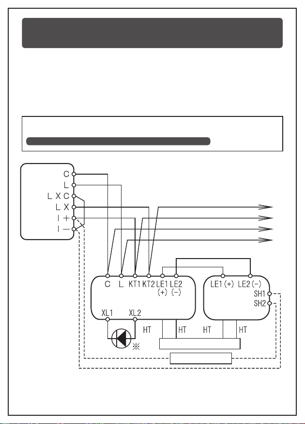
Connection shall be made as shown below.(Applicable wire for the terminal
base of the detector is a single line, φ0.4 to φ1.6.)
● Line resistance between the fire control panel and the light receiver of the
detector (C-L, KT1-KT2) shall be 50Ω or less.
● Line resistance between the light transmitter and the light receiver of the
detector (LE1, LE2) shall be 30Ω or less.
※As the remote indicator lamp FLL061 and the signal transmission adaptors
FRL014,pay attention to the polarities of the terminals XL1 and XL2.
As the synchronization lines(LE1(+), LE2(-))has the polarities, pay attention to
their connection. As for connection of the heater, refer to
10. CONNECTION OF HEATER (HEATER TYPE ONLY) on Page11.
8. CONNECTION WITH FIRE CONTROL
PANEL
Power supply for heater
Test push button
Light receiver Light transmitter
Next detector
P- type
(conventional)
fire
control
panel

- 9 -
9. INSTALLATION/CONNECTION/SETTING
As fine adjustment is to be performed on the light transmitter, install the light
receiver and adjust the light axis of the light receiver first, and then, install the
light transmitter and adjust the light axis of the light transmitter.
When installing and operating this product, pay attention to the following matters.
● Be sure to arrange a secure scaffold.If not, an installation worker
may fall down the scaffold and be injured.
● Mount the light transmitter and receiver of the detector on the rigid
wall and the like. If installed on an unstable location, the detector
may not perform normal monitoring.
①Loosen
②Open
④Remove
③Loosen
⑤Fix
⑥Tighten
Body
If loosen the cover fixing screw,
the cover moves toward you.
INSTALLATION
WARNING
CAUTION
Make sure that the cover is
secured to the cover hooks on
both sides of the detector base.
If not, the cover may drop.
Cover
INSTRUC-
TIONS
- 10 -
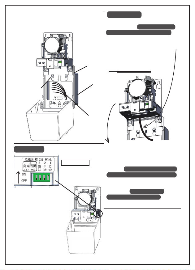
Securely fix the detector to the switch
box with four M4 screws
In case of the
light receiver , set
the monitoring
range and the light
emission cycle.
S:(ON)Short range
(5-20m)
M:(ON)Medium range
(20-40m)
L:(ON)Long range
(40-100m)
CONNECTION
SETTING
Base
Switch box
Wire
⑧Insert the wire into the terminal
base. Refer to 8. CONNECTION
WITH FIRE CONTROL PANEL on
Page 8.
As the terminals LE1(+) and LE2(-)
have the polarities, pay attention
when connecting the wire.
Applicable wire : φ0.4 to 1.6mm
Strip gage : 10mm
⑨Remove the body and mount it
again to the original position and
tighten the two screws.
As for connection of the heater,
refer to 10. CONNECTION OF
HEATER (HEATER TYPE ONLY)
on Page 11.
After installing the light transmitter,
proceed to 11. LIGHT AXIS
ADJUSTMENT METHOD
on Page 12.
⑦Tighten
⑩Select
LT. / TMG.:
The light emission cycle:
(ON) 2.8 second / (OFF) 3.0 second
Please refer to next page for details.

- 11 -
10. CONNECTION OF HEATER
(HEATER TYPE ONLY)
To prevent interference, set the light emission cycle No.4 of
the adjoining detectors to ON and OFF alternately.
To install the heater type (Models FDGJ103-D-XHT and 203-D-XHT), connect
the heater with the power supply for heater.
Connect the heater with the power lines of
heater by means of insulated open-end
connectors and apply waterproof treatment
to the connection by means of self-fusing
tape and the like.
Setting of Monitoring Range and Light Emission Cycle
S:(ON) Short range (5-20m)
1:(ON)
M:(ON) Medium range (20-40m)
2:(ON)
L:(ON) Long range (40-100m)
3:(ON)
INSTRUC-
TIONS

- 12 -
11. LIGHT AXIS ADJUSTING METHOD
11.1. Coarse Adjustment with Collimation Hole (Common to Light
Transmitter and Receiver)
View the mirror through the viewing hole, and turn the light axis adjusting
screw(s) (vertically and/or horizontally) so that opposing light receiver
(viewed from the transmitter) and the opposing JIS box (viewed from the
receiver) may be located in the viewing hole.
Image Viewed through Viewing Hole
Light Receiver: Opposing JIS Box
Light Transmitter : Opposing Light Receiver
When the heater (for preventing dew condensation) is energized,
it becomes hot (about 60°C). Therefore, pay attention not to
touch it during the installation work. If touched, it may cause you
to be burnt.
HIGH
TEMP.
After adjusting the light axis, set the cover again and tighten the
screw. In case of the light transmitter, proceed to the installation
of the light transmitter (Paragraph 9 on Page 9) and in case of
the light transmitter, proceed to Para.11.2 on the next page.
INSTRUC-
TIONS
Viewing hole
Heater
Collimation
hole
Mirror
Light axis adjusting
screw (Vertical)
Light axis adjusting
screw (Horizontal)

- 13 -
INSTRUC-
TIONS
CAUTION
11.2. Power Energization (Recommend to energize to Light Transmitter)
Connect the battery connector for detector test to the connector on the left
side of the detector (when viewed from the front of the detector), and next,
connect the battery connector for detector test to the auxiliary battery. In
this case, the Adjustment Mode alone is effective. (In case that no battery
is available, turn ON the power of the fire control panel.)
11.3. Switchover of Adjustment Mode
(Recommend to switch over Adjustment Mode on Light Transmitter)
At a lapse of about 10 seconds after power
ON, the detector
becomes operational.(In case that the power is
fed through the battery connector of the light
receiver, the green LED of the receiver lights
every 3 seconds. When the power is fed to the
light transmitter, the green LED of the receiver
does not light.
Stand at a position so that you may not
interrupt the light axis (You can see the
detector as shown on the left figure.).
Press MONITOR/ADJUST. Switch for one
second and then, release the switch, and the
indicator lamps emit lights as follows ;
※In case of the light receiver, operate the
MONITOR/ADJUST. Switch in the same way.
(Light Transmitter : Green and red LEDs light at
the same time and then, flicker alternately.)(Light
Receiver : Yellow LED flickers every one
sec.)Wait (about 4 sec.) until alternate
flickering of the indicator lamps is finished.
The power can be supplied through the battery connector of the
light transmitter or light receiver or the terminals C and L of the
light receiver. To avoid a malfunction, ensure that the power is
supplied via one route.
No adjustment can be made when the Fire Alarm Lamp on the
light receiver is lighting. In case that the power is supplied
through the battery connector of the light receiver, pull out the
battery connector and wait for about 15 seconds. Then, connect
the battery connector again.
Auxiliary battery
Battery connector for detector test

- 14 -
Image of the Paragraphs 11.4 and 11.5 on Page 15 and Paragraph 12 on Page
17 is shown below.
The relationship between the light emission pattern and output of the light
transmitter in case of the light axis adjustment is as follows.
To ensure stable monitoring of the detector for long period, set the light
output to the peak as possible as you can according to the following steps
①→② (Allowance for imperfect alignment of light axis generated after
installation).
①Turn the Light Axis Adjusting Screw until green flickering of the indicator lamp
(Power Lamp) of the light transmitter becomes red on the left and right side
ends. Then, set the light axis to the center within the green flickering range.
②Adjust the light axis in the vertical direction in the same manner as stated in
the above ①
①②
The relationship between
the light axis and flickering
pattern of the indicator
lamp :
Flickering pattern of the
indicator lamp may change
due to light axis adjustment
on the light transmitter.
GreenGreen
Red
Red
Image of Fine Adjustment of Light Trnsmitter
Turn the light axis adjusting
screw.
Turn the light axis adjusting
screw oppositely.

- 15 -
11.4. Fine Adjustment of Light Transmitter (in Horizontal Direction)
Turn the Light Axis Adjusting Screw (Horizontal), and the flickering pattern
of the green indicator lamp changes according to the condition of the
received light output.
11.6 Switchover of Monitoring Mode
If the green indicator lamp flickers after
adjusting the light axis in the vertical
and horizontal directions, press the
MONITOR/ADJUST. Switch for two
seconds or over and then,release it.
(Both the green and red indicator
lamps light at the same time.)
Adjust the light axis in the vertical
direction in the same manner as
described in the above 11.4.
11.5 Fine Adjustment of Light Transmitter (in Vertical Direction)
CAUTION
DO NOT use a motor-driven
screwdriver. If used, it may
cause the screw to be
damaged.
DO NOT interrupt the light axis during the switchover of the
Adjustment and Monitoring Modes.
Normally, the indicator lamp flickers in
green first. Turn the screw clockwise or
counterclockwise to flicker it in red.
Change flickering of the lamp in the
order of “red→green→red” and check
the range of green flickering and align
the light axis to the center of it.
Make the fine adjustment of the light axis by means of the Light Axis Adjusting
Screw so that the indicator lamp (Power Lamp) of the light transmitter flickers
only in green.
After green flickering of the indicator lamp goes out, pull out the battery
connector for detector test. In case that the power is fed through the
terminals C and L, it is not necessary to cut off the power supply of the fire
control panel.
Image of light emission pattern in
Horizontal direction (Viewed from
the top.)
Image of light emission pattern in
Vertical direction
(Viewed from the side.)
INSTRUC-
TIONS
Refer to Para.12 LIGHT AXIS ADJUSTMENT METHOD
(FLICKERRING PATERN)
Red
Red
Green
Red
Green
Red

- 16 -
11.7. Mounting of Cover (Completion of Adjustment)
Close the cover and tighten the screw. If tightened,
the cover, is fixed to the detector body.
Indicator Lamp
Red
Red (quick
flickering)
Green
Green (quick
flickering)
Green/Red
(simultane-
ous
flickering)
In case of
Trouble
①
②
③
④
Flickering Pattern Status/Operation
In case that the power is fed from the fire control panel, be sure
to close the cover within one minute after green flickering of
the indicator lamp goes out.(If the cover is closed after a lapse
of more than one minute, the detector may fail to monitor fire
properly.
If the status of the indicator lamp (②RED, quick flickering) in the
above table does not change, chek the setting of monitoring range
of the light receiver and press the MONITOR/ADJUST. Switch.
INSTRUC-
TIONS
Initial stage of adjustment
:Turn the Light Axis Adjusting Screw
clockwise or counterclockwise.
Insufficient output of received light
:Turn the Light Axis Adjusting Screw in
the reverse direction of the above ①.
Sufficient monitoring output
:Set the light axis in the center of this
range (In case that the indicator lamp
does not flickers quickly.).
Increase in output of received light
: Set the light axis in the center of this
range.
Check for the request of switch
operation (output saturation and the
like) and status of light receiver/
transmitter, and press the MONITOR/
ADJUST. Switch.
In this case, NEVER touch the front plate (black) as the
light output may lower due to contamination of the front plate.
INSTRUC-
TIONS
11.8. List of Flickering Patterns

- 17 -
Flow of Fine Adjustment
1
2
3
4
Flickering Pattern of Indicator
Lamps on Light Transmitter
Green and red
indicator lamps
flicker at the same
time.(one time)
Green and red indicator lamps
flicker alternately.
Green indicator lamp starts
flickering.
Green indicator lamp flickers.
Red indicator lamp flickers.
Operation and flickering pattern of the indicator lamps on the light transmitter
during light axis adjustment are as shown in table below.
Adjustment
Press the MONITOR/ADJUST. Switch for
one second and then, release it.
Wait for about four seconds, without
interrupting the light axis by your hand or
body and the like.
Turn the Light Axis Adjusting Screw
clockwise to the point that the green
indicator lamp stops flickering and the red
one starts flickering.
Then, the green indicator lamp alone starts
flickering. As it means that you are ready
for light axis adjustment, perform the steps
4 to 6 below in every four directions
(UP/DOWN/LEFT/RIGHT) respectively to
align the light axis to the center.
(If the light axis is interrupted by your hand
or body and the like, the red indicator starts
flickering. In this case, repeat the same
operation from the above step 1 again.)
12. LIGHT AXIS ADJUSTING METHOD
(FLICKERING PATTERN)

- 18 -
6
7
Flickering Pattern of Indicator
Lamps on Light Transmitter
Red indicator lamp flickers.
Green indi cator lamp flickers.
Green indicator lamp flickers.
Green indicator lamp flickers
quickly.
Green indicator lamp flickers.
Green and red indicator lamps
flicker at the same time.
Green indicator lamp flickers.
Green indicator lamp goes out.
Adjustment
Set the light axis to the center of green
flickering range.
(Turn the screw clockwise by the half
volume turned counterclockwise at the
above step 5.)
When the Light Axis Adjusting Screw is
turned, flickering of the green indicator
lamp may turn into quick flickering. In this
case, set the light axis to the center of
green quick flickering range (Turning
volume of the screw can be reduced.)
Press the MONITOR/ADJUST. Switch for
2 seconds, and release it, and the green
and the green and red indicator lamps
flicker at he same time. Then, the green
lamp alone flickering and finally it goes out.
After the green indicator lamp goes out,
mount the cover.
Supplement
Red indicator lamp flickers.
Green indicator lamp flickers.
Red indicator lamp flickers.
5
Turn the Light Axis Adjusting Screw
counterclockwise to the point that the red
indicator lamp stops flickering and the
green one starts flickering and next, the
green indicator lamp stops flickering and
the red one starts flickering again.
This manual suits for next models
1
Table of contents
Other NOHMI Security Sensor manuals

Popular Security Sensor manuals by other brands


SKF
SKF TKSU 10 Instructions for use

IFM Electronic
IFM Electronic efector300 SM8001 operating instructions

B.E.G.
B.E.G. LUXOMAT PD4-S-K manual

PCB Piezotronics
PCB Piezotronics 109C11/PCS-2AF Installation and operating manual

Korno
Korno GT-1000 SERIES user manual

Antec Scientific
Antec Scientific FlexCell user manual

Versahaul
Versahaul VH-SR quick start guide

Niko
Niko 25421 quick start guide

TOOLCRAFT
TOOLCRAFT OG08 operating instructions

Autronica
Autronica AutroSense 75 Installation & Commissioning Handbook

Elenco Electronics
Elenco Electronics AK-510 Assembly and instruction manual

AJAX Systems
AJAX Systems DoorProtect user manual