7
Programming
In the programming state the sensors, alarms and
scaling of pulses are chosen. The programming state is
achieved by pressing the star buttons and arrow but-
tons simultaneously for about 2 seconds. The text
Pulse appears in the display. With the arrow keys you
move upwards in submenu or in basic menu. By the
desired function you move to the arrangement state
with the star button and returned to the main menu
with same button. When all arrangements have been
made,you move to SAVE - UNDO - menu, with star
key. SAVE accepts with the button ➤the changes
and UNDO cancels the changes.
Programming parameters
Main Me
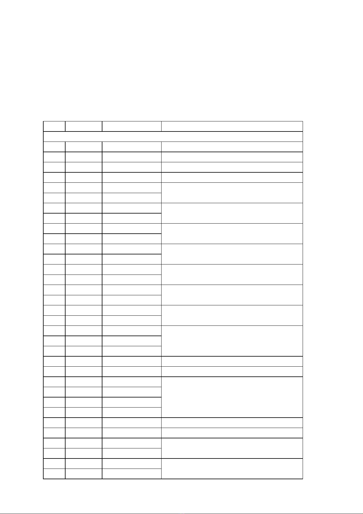
Selection Menu Term Description
▲▼ move up/down in the menu ➤move to the adjustment state/ the next level x accept the selection / return back
Pulse Pulse multiplier value The numerical value that 1 pulse corresponds to on the display. The value can
also be a decimal.
Divide Pulse divider value To be used in special cases when not enough decimals can be set with the
multiplier value, please see the example*.
Start Start value for counting The value from which the counter starts the counting.
Limit Alarm limit The counter value at which the relay is energized.
Adjust Start Fast setting of Start value
Limit Fast setting of Limit value
Loop On Loop function activated
Off Loop function off
Res bl On External reset prevented
Off External reset allowed
Check On Check of Start / Limit values
Off Checking not in use
Contac No Closing contact
Nc Opening contact
PO res On
Off
Direct Up Counting upwards
Down Counting downwards
d Swit Off Not used
Nc Change of the counting direction
when the contact is opened.
No Change of the counting direction
when the contact is closed.
Dec Number of decimals Number of the decimals to be shown on the display.
Int 0…15 Brightness of the display Adjustment of the brightness of the display: 0…15.
Sensor NPN (Contact) Selection of the sensor type
PNP
Namur
Pickup
Baud r 300…19200 Baud rate Baud rate selection : 300…19200
Addres Addre 0…127 Serial communication address Selection of the serial communication address: 0…127
RS-485 Off Serial output card RS-485 not
used
Slot B Serial output card RS-485
inserted into Slot B
Save Saving the settings
Undo Cancelling the settings
Selection of the sensor type. Please NOTE! If a closing contact is used as the
sensor, one should select NPN as the sensor type.
Selection of the serial output card RS-485 for use. Please NOTE! If serial
output RS-232 is used it need not be selected.
You can enter the Save and Undo state from the Main Menu by the ★-key.
The selection is accepted by the ➤-key.
Selection of the direction for the relay function.
When connecting the power supply to the counter the PO res setting can
prevent the start of the counting if Nc has been selected as the direction for
the alarm relay function.In this case the counting will not start until after the
Reset function.
Selection of the counting direction: upwards or downwards.
Change of the counting direction of counter via an external contact on the
2000-I/O card.
The start value (Start) of the counting or the alarm limit value (Limit) can be
changed directly in the display state without entering the configuration state.
When the loop function is selected (On), the counter resets and at the same
time starts a new count automatically when the alarm limit is reached.
Interlock of the external reset contact during counting. Reset can be
performed only after the alarm limit has been reached. Does not prevent the
reset via front panel.
When resetting the counter the first push of the reset button displays the value
set in the Adjust state (Start or Limit). The second push resets the counter.