Nokia 6650 - Smartphone 40 MB User manual

nokia
CONNECTING PEOPLE PAGE 1 (25) Approved 2.0
Customer Care EMEA DJk
Technical Services, Repair Concepts Confidential 21.01.2004
nokia
6650
NHM-1
Transceiver Features
Transceiver main HW parts/ features include:
• WCDMA/GSM900/PCN1800/GPRS
• Bluetooth and IR for cordless communication
• USB data transfer and connectivity with a PC
• Full graphic Colour Display
• UI with two soft keys and four way+ select navigation key
• Integrated IR link & internal data
• Internal Hands Free (IHF) Speaker
• Pop-Port ™ accessory interface
• Plug-in SIM card
• External WCDMA antenna
• Internal GSM 900/1800 antenna and BT antenna
• Integrated digital camera providing video and still picture
• Polyphonic ringing tones
• Voice recognition: 50 names and commands
• Built-in recorder up to 4min 20sec
Transceiver with BLC-2 1000mAh Li-ion battery pack
Talk time Standby Note
Up to 2h - 3h 10min (WCDMA)
Up to 3h 10min - 4h 20min (GSM) Up to 7 - 14
days
Depends
on network
parameters
SERVICE MANUAL
Service Level 1&2
Copyright © Nokia Corporation. This material, including documentation and any related computer
programs, is protected by copyright controlled by Nokia Corporation. All rights are reserved.
Copying, including reproducing, storing, adapting or translating, any or all of this material requires
the prior written consent of Nokia Corporation. This material also contains confidential information,
which may not be disclosed to others without the prior written consent of Nokia Corporation.
Service Manual 6650 Level 1&2 Copyright 2003-2004 © Nokia Corporation

nokia
CONNECTING PEOPLE PAGE 2 (25) Approved 2.0
Customer Care EMEA DJk
Technical Services, Repair Concepts Confidential 21.01.2004
TABLE OF CONTENT
Page
1. INTRODUCTION......................................................................................................................................3
2. GENERAL REPAIR INFORMATION ...................................................................................................4
3. PATHFINDER FOR WORKSHOP STAFF............................................................................................5
4. EXPLODED VIEW AND COMPONENT DISPOSAL..........................................................................6
5. SPARE PARTS LIST.................................................................................................................................7
6. SERVICE TOOLS......................................................................................................................................9
7. SW-UPDATE............................................................................................................................................11
8. DISASSEMBLY INSTRUCTIONS (ALSO SEE THE VIDEO CLIPS ON CARE POINT)............12
9. LEGEND FOR QUICK TROUBLE SHOOTER..................................................................................16
10. QUICK TROUBLE SHOOTER PART 1 ..........................................................................................17
11. QUICK TROUBLE SHOOTER PART 2 ..........................................................................................18
12. QUICK TROUBLE SHOOTER PART 3 ..........................................................................................19
13. CAMERA GONOGO TEST................................................................................................................20
14. BLUETOOTH AND INFRARED GONOGO TEST ........................................................................21
15. GONOGO TEST ..................................................................................................................................22
16. BATTERY TEST..................................................................................................................................22
17. SERVICE NOTES................................................................................................................................23
18. FORWARDING OF REPAIRS TO SERVICE LEVEL 3 OR 4 SUPPLIERS...............................24
19. ESD PROTECTION REQUIREMENTS...........................................................................................25
CHANGE HISTORY
Status Version No. Date Comments
Draft 0.1 23.04.2003 Initial draft
Approved 1.0 16.07.2003 Approval
Draft 1.1 19.11.2003 Service manual Level 1&2 full version
Approved 2.0 21.01.2004 Approval
Service Manual 6650 Level 1&2 Copyright 2003-2004 © Nokia Corporation

nokia
CONNECTING PEOPLE PAGE 3 (25) Approved 2.0
Customer Care EMEA DJk
Technical Services, Repair Concepts Confidential 21.01.2004
1. INTRODUCTION
The purpose of this document is to help Nokia service levels 1 and 2 workshop technicians to carry out
service to Nokia 6650. This Service Manual is to be used only by authorized Nokia service partners, and the
content of it is confidential. Please note that Nokia provides also other guidance documents (e.g. Service
Bulletins) for service partners, follow these regularly and comply with the given instructions.
While every endeavor has been made to ensure the accuracy of this document, some errors may exist.
If you find any errors or if you have further suggestions, please notify Nokia using the address below:
mailto:[email protected]
Please keep in mind also that this documentation is continuously being updated and modified, so watch
always out for the newest version.
Warnings and Cautions
Please refer to the phone’s user guide for instructions relating to operation, care and maintenance
including important safety information. Note also the following:
Warnings:
1.
2.
3.
CARE MUST BE TAKEN ON INSTALLATION IN VEHICLES FITTED WITH ELECTRONIC ENGINE
MANAGEMENT SYSTEMS AND ANTI–SKID BRAKING SYSTEMS. UNDER CERTAIN FAULT CONDITIONS,
EMITTED RF ENERGY CAN AFFECT THEIR OPERATION. IF NECESSARY, CONSULT THE VEHICLE
DEALER/MANUFACTURER TO DETERMINE THE IMMUNITY OF VEHICLE ELECTRONIC SYSTEMS TO RF ENERGY.
THE HANDPORTABLE TELEPHONE MUST NOT BE OPERATED IN AREAS LIKELY TO CONTAIN
POTENTIALLY EXPLOSIVE ATMOSPHERES EG PETROL STATIONS (SERVICE STATIONS), BLASTING AREAS ETC.
OPERATION OF ANY RADIO TRANSMITTING EQUIPMENT, INCLUDING CELLULAR TELEPHONES, MAY
INTERFERE WITH THE FUNCTIONALITY OF INADEQUATELY PROTECTED MEDICAL DEVICES. CONSULT A
PHYSICIAN OR THE MANUFACTURER OF THE MEDICAL DEVICE IF YOU HAVE ANY QUESTIONS. OTHER
ELECTRONIC EQUIPMENT MAY ALSO BE SUBJECT TO INTERFERENCE.
Cautions:
1. Servicing and alignment must be undertaken by qualified personnel only.
2. Ensure all work is carried out at an anti–static workstation and that an anti–static wrist strap is
worn.
3. Ensure solder, wire, or foreign matter does not enter the telephone as damage may result.
4. Use only approved components as specified in the parts list.
5. Ensure all components, modules screws and insulators are correctly re–fitted after servicing and
alignment. Ensure all cables and wires are repositioned correctly.
6. All PC’s used with Nokia Service Software for this produce must be bios and operating system
”Year 2000 Compliant”.
Electrostatic discharge can easily damage the sensitive components of electronic
products. Therefore every Service Supplier has to take care of all precautions, which are
mentioned in the service level related “Service Partner Requirements”, available on
Nokia Partner Web Site. Also see ESD Protection Requirements in this Service Manual.
Service Manual 6650 Level 1&2 Copyright 2003-2004 © Nokia Corporation

nokia
CONNECTING PEOPLE PAGE 4 (25) Approved 2.0
Customer Care EMEA DJk
Technical Services, Repair Concepts Confidential 21.01.2004
2. GENERAL REPAIR INFORMATION
IN THIS SECTION THE TECHNICIAN WILL GET SOME GENERAL HINTS HOW TO CARRY OUT REPAIRS:
o To familiarize oneself with Nokia 6650 read the tutorials or user guide on
www.nokia.com -->Support--> Phones, by selecting the Phone Model.
o Before starting the repair you must take care of ESD precautions like being in your ESD Protected Area
and connecting your wristband.
o Use gloves to avoid corrosion and fingerprints.
o Protect windows and displays with a film to avoid dust and scratches.
o When cleaning the pads you have to use a soft cloth/ESD brush and Isopropanol. It is not allowed to use
a glass fiber pencil because it scratches the surface and will lead later on to corrosion.
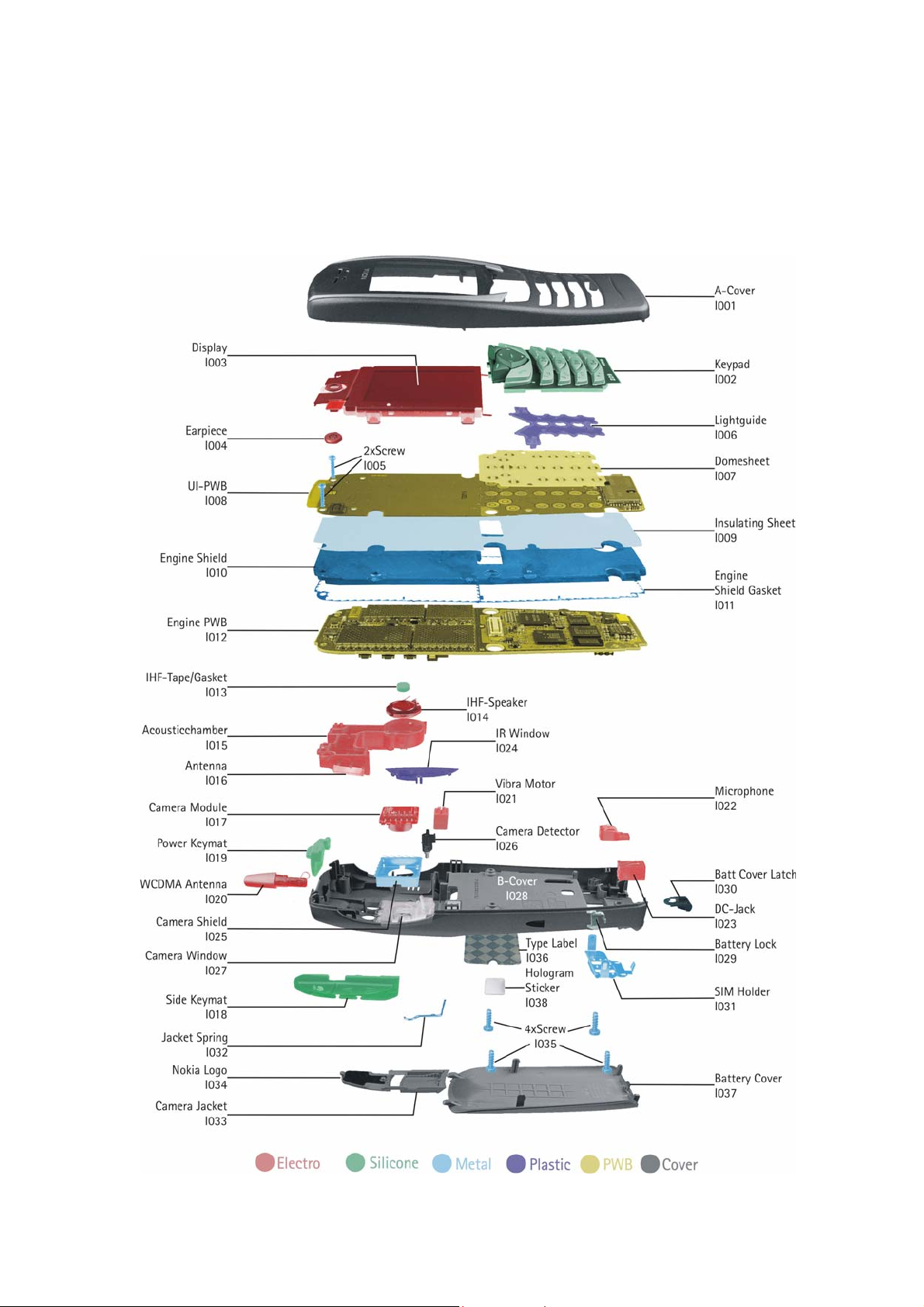
o Mechanical parts (except shielding lids), which didn’t repair the failure, can be reused, if they are not
soldered.
o When removing the shielding lids make sure to replace them with new ones, otherwise the high-
frequency leakage can have an influence on the device.
o Use always original Nokia spare parts.
o Check the soldering joints of the parts which are concerned regarding the indicated error
(e.g. soldered connectors or switches) and resolder them if necessary (Level 2 only).
o Remove redundant soldering flux after repair.
o Meet the torque requirements when assembling the unit (see also the document “torques for
transceiver assembly” on Nokia Partner Web Site).
o Always use your own equipment for testing where you are sure that it works. E.g. if the customer
complains about charger function, please test the phone with your own charger to be sure if phone or
charger causes the malfunction.
o When doing the Faultlogger entries, always note the Item code, which caused the malfunction. Also, fill
in the appropriate part code from the assembly, if needed.
o Please be aware that some malfunctions could be software related and solved by an update.
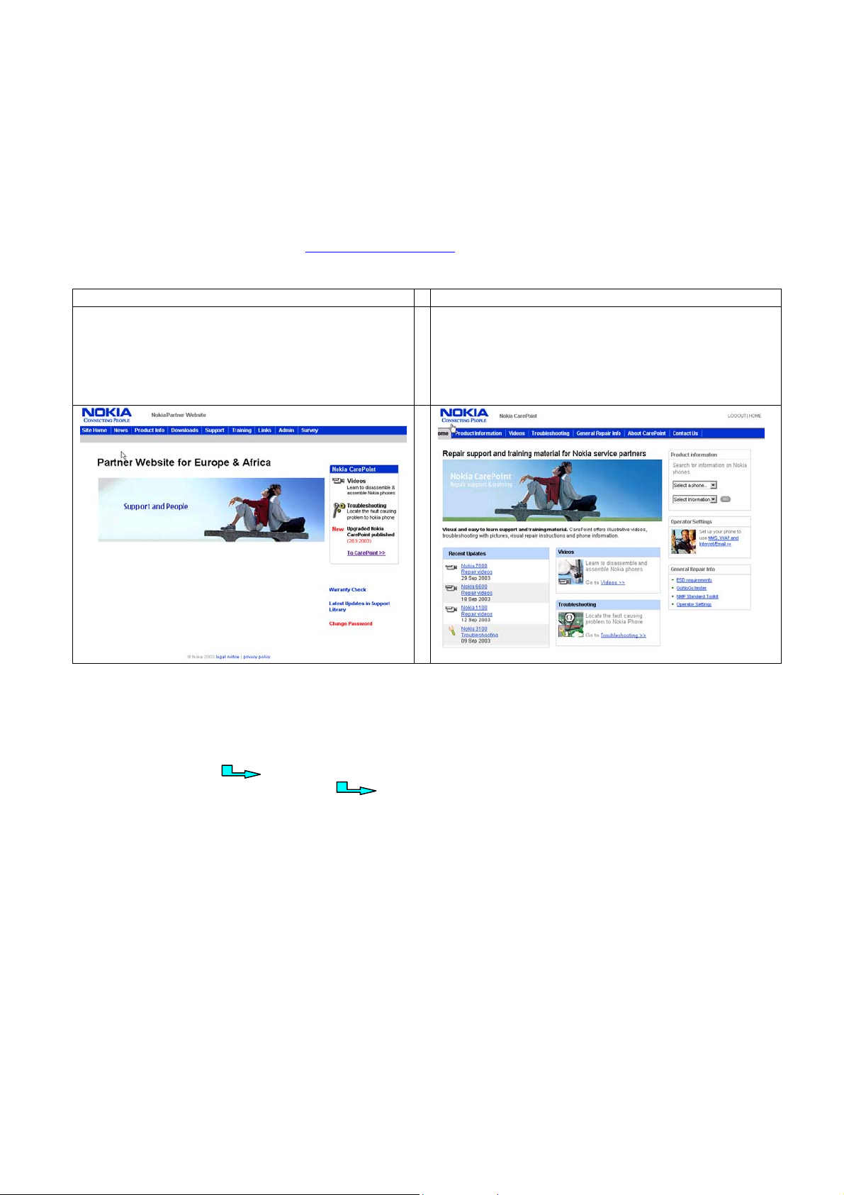
There are several Service Bulletins, which have to be followed:
First, take care for the latest content pages of Service Bulletins, which are always available on
Nokia Partner Web Site. This is also important to recognize, if existing Bulletins have become invalid.
The service level indicator at the bottom of each document tells the appropriate destination.
Downloads > Support Library >
• General Service Bulletins
• Service Tools Service Bulletins
• Spare Part Service Bulletins
• Common Softwares Service Bulletins
• Instructions
• etc,…
Please check Nokia Partner Web Site (PWS) for latest news and files on a regular basis.
Service Manual 6650 Level 1&2 Copyright 2003-2004 © Nokia Corporation

nokia
CONNECTING PEOPLE PAGE 5 (25) Approved 2.0
Customer Care EMEA DJk
Technical Services, Repair Concepts Confidential 21.01.2004
3. PATHFINDER FOR WORKSHOP STAFF
In addition to the information in this Service Manual, there are several instructions and information, which
have to be followed.
Main documentation database is Nokia Partner Website, which refers also to Nokia Care Point with the
purpose of serving different multimedia content, like video clips or interactive tutorials.
Nokia Partner Web Site Nokia Care Point (access through Partner Web Site)
Nokia Partner Web Site for EMEA region is the most important
document database for all service suppliers (level 1-4). All
service relevant information like e.g. Service Manuals, Service
Bulletins or general instructions are available. Content is
restricted according your access level. To be kept up-to-date
also concerning newest software updates, a daily check of
“latest updates in support library” is needed.
Nokia Care Point is repair support and training channel for Nokia
service suppliers (mainly for service levels 1 and 2). By providing
visual and easy to learn support and training material, such as
illustrative repair videos, troubleshooting with pictures, product
information and general repair information, Nokia Care Point
offers user-friendly channel for service partners to learn technical
issues.
It is mandatory to watch for newest technical and organizational information on a daily basis to be
updated as required (see “Latest Updates in support Library”). Every new information has to be processed
and implemented as soon as possible.
When logged into PWS you can also find needed information in different folder like:
Downloads
Support Library
Accessories
Battery Tester
Common Software
Flashing Tools
General --> Instructions
GoNoGo Tester
Service Tools
Tester Support
Wintesla
Products (Service Manuals, Service Bulletins)
To spare server bandwidth it is recommended to download newest version of huge files like videos,
Phoenix packages or Service Manuals only once and distribute it internally for further use.
Service Manual 6650 Level 1&2 Copyright 2003-2004 © Nokia Corporation

nokia
CONNECTING PEOPLE PAGE 6 (25) Approved 2.0
Customer Care EMEA DJk
Technical Services, Repair Concepts Confidential 21.01.2004
4. EXPLODED VIEW AND COMPONENT DISPOSAL
Recommendation for the ecologically friendly disposal of components. Colorized components show the different categories.
Description: See corresponding ITEM/CIRCUIT REF of the SPL (Spare Parts List)
Service Manual 6650 Level 1&2 Copyright 2003-2004 © Nokia Corporation

nokia
CONNECTING PEOPLE PAGE 7 (25) Approved 2.0
Customer Care EMEA DJk
Technical Services, Repair Concepts Confidential 21.01.2004
5. SPARE PARTS LIST
MECHANICAL PARTS
ITEM/
CIRCUIT REF. QTY PART NO PART NAME
I001 1 9490522 A-COVER
I002 1 9794091 KEYPAD
1 4850301 DISPLAY MODULE ASSY
I003 1 - DISPLAY
I004 1 5140247 EARPIECE
I005 2 6150071 SCREW M1.8X11
1 9498000 UI-PWB ASSY
I006 1 9460457 LIGHT GUIDE
I007 1 - DOME SHEET
I008 1 - UI-PWB
1 9517190 ENGINE SHIELD ASSY
I009 1 - INSULATING SHEET
I010 1 - ENGINE SHIELD
I011 1 - ENGINE SHIELD GASKET
I012 1 - ENGINE PWB
1 9481208 ANTENNA ASSY
I013 1 - IHF-TAPE / GASKET
I014 1 - IHF-SPEAKER
I015 1 - IHF-ACOUSTICCHAMBER
I016 1 - ANTENNA
I017 1 4858013 CAMERA MODULE
I018 1 9790655 SIDE KEYMAT
I019 1 9790654 POWER KEYMAT
I020 1 0660243 WCDMA ANTENNA
I021 1 6800055 VIBRA
I022 1 5140265 MICROPHONE
I023 1 5400243 DC-JACK
I024 1 9452407 IR WINDOW
1 - B-COVER ASSY
I025 1 - CAMERA SHIELD
I026 1 - CAMERA DETECTOR
I027 1 - CAMERA WINDOW
I028 1 - B-COVER
I029 1 9470163 BATTERY LOCK
I030 1 9470162 BATTEY COVER LATCH
I031 1 9517112 SIM-CARD HOLDER
Service Manual 6650 Level 1&2 Copyright 2003-2004 © Nokia Corporation

nokia
CONNECTING PEOPLE PAGE 8 (25) Approved 2.0
Customer Care EMEA DJk
Technical Services, Repair Concepts Confidential 21.01.2004
ITEM/
CIRCUIT REF. QTY PART NO PART NAME
I032 1 9510921 JACKET SPRING
I033 1 9458438 CAMERA JACKET
I034 1 9430418 NOKIA LOGO
I035 4 6290093 SCREW M1.8X8
I036 1 - TYPE LABEL
I037 1 9452413 BATTERY COVER
I038 1 9381333 HOLOGRAM STICKER
SOLDERING COMPONENTS ONLY FOR LEVEL 2
ITEM/
CIRCUIT REF. QTY PART NO PART NAME
S165 1 5209001 SM SW TACT SPST 12V 50MA SIDE KEY
S166 1 5209001 SM SW TACT SPST 12V 50MA SIDE KEY
S167 1 5209001 SM SW TACT SPST 12V 50MA SIDE KEY
S170 1 5209001 SM SW TACT SPST 12V 50MA SIDE KEY
F100 1 5119019 SM FUSE F 1.5A 32V
V101 1 4864525 LED CL270WBKE ** RESERVED HDAF3**
V102 1 4864525 LED CL270WBKE ** RESERVED HDAF3**
B253 1 4700135 CELL CAPACITOR
SWAP UNITS
QTY PART NO PART NAME
0079153 NHM-1 N6650 SWAP UNIT EUROP&AFRICA
Service Manual 6650 Level 1&2 Copyright 2003-2004 © Nokia Corporation

nokia
CONNECTING PEOPLE PAGE 9 (25) Approved 2.0
Customer Care EMEA DJk
Technical Services, Repair Concepts Confidential 21.01.2004
6. SERVICE TOOLS
0080541 FLS-4S incl. ACF-8, Driver and User Guide
is a dongle and flash device incorporated into one package,
developed specifically for POS use.
0680032 ACF-8
Universal Power Supply is used to power FLS-4S.
0271738 Internal Battery BLC-2
Inserted under the back cover, this Li-Ion 1000 mAh battery
provides power in a lightweight package.
0272169 Travel Charger ACP-8E
0272172 Travel Charger ACP-8X
Small and lightweight charger for fast charging of your
phone battery.
0274086 Headset HS-5
An easy and convenient handsfree solution with remote
control.
0273636 Stand DCV-14
Provides easy charging and convenient data synchronization
with a compatible computer using the Connectivity Adapter
Cable DKU-5 (supplied separately).
0730218 XCS-1
Service Cable is used to connect FLS-4S to FLA 25.
0770326 FLA-25
POS Flash Adapter is used in POS (Point of Sales) environment
for software updating. It provides controlled supply voltage
and necessary connections between the phone and the Flash
Device. It substitutes for the phone’s standard battery during
the software update.
0770450 New Test Pins
for Flash Adapter FLA-25
Service Manual 6650 Level 1&2 Copyright 2003-2004 © Nokia Corporation

nokia
CONNECTING PEOPLE PAGE 10 (25) Approved 2.0
Customer Care EMEA DJk
Technical Services, Repair Concepts Confidential 21.01.2004
0730238 Nokia Connectivity Cable DKU-2
A USB cable for connecting a compatible PC and Nokia phone.
This cable supports the use of Nokia PC Suite software. It
enables transfer and synchronization of different data types -
for example calendar, phonebook, notes, to-do list-
depending on Nokia PC Suite version.
0770494 MJS-89
Soldering Jig (for Level 2 or higher service level supplier).
0772040 NMP Standard Toolkit
Nokia opening tool SRT-6 Nokia No. 0770431
Tonichi torque driver Nokia No. 6901525
Hoya micro fibre cloth MX304
Dastex gloves S, M, XL
Artilux goggles AH166
Wera bit T5 867/4TX 5x50
Wera bit T6 867/4TX 6x50
Wera bit T6 PLUS®867/4TX 6IP
Facom side cutter 416E
Facom T5 driver SP.14032
Facom T6 driver SP.14033
Facom slot screwdriver AEF. 2x35.E
Wetec tweezers 7abb SA-ESD
Wetec tweezers 22 SA-ESD
Wetec tweezers 13 SA-SMD ESD
Wetec tweezers PSF SA-ESD
Wetec ESD brush E1211
Kaiser Fototechnik airbrush 6315
Wetec dental tool DEM83266/0
RS Components Scissors 323-5732
Service Manual 6650 Level 1&2 Copyright 2003-2004 © Nokia Corporation

nokia
CONNECTING PEOPLE PAGE 11 (25) Approved 2.0
Customer Care EMEA DJk
Technical Services, Repair Concepts Confidential 21.01.2004
7. SW-UPDATE
To use FLS-4S Flash Dongle you have to follow the user guide inside the sales package. Please check always
for the latest version of flash software, which is available on
Nokia Partner Web Site.
Flash Concept – (Point of Sales)
It is very important to follow this insertion and
removal procedure, otherwise the contact pins of Flash
Adapter will be damaged.
Insert the Flash Adapter FLA-25 like a battery, start at
the Battery Connector side.
Now, push down the bottom side of the phone, do not
use too much force.
When removing the phone, always start from the
bottom side of the unit.
Take away the unit now.
Service Manual 6650 Level 1&2 Copyright 2003-2004 © Nokia Corporation

nokia
CONNECTING PEOPLE PAGE 12 (25) Approved 2.0
Customer Care EMEA DJk
Technical Services, Repair Concepts Confidential 21.01.2004
8. DISASSEMBLY INSTRUCTIONS (ALSO SEE THE VIDEO CLIPS ON CARE POINT)
If not already done protect window with a film to
avoid dust and scratches.
Remove the Battery Cover.
The Nokia Logo is attached with an adhesive tape.
Remove it carefully by using the opening tool.
The Camera Jacket is attached with two hooks in its
guidance. Push out the Camera Jacket with SRT-6
carefully, using additional force.
Unscrew the four TORX PLUS® size 6 screws, using the
order shown. For assembly, the same order and
a torque of 24Ncm have to be used.
Now, remove the A-Cover.
Protect window to avoid dust and scratches.
Protect LCD with a film, too.
Service Manual 6650 Level 1&2 Copyright 2003-2004 © Nokia Corporation

nokia
CONNECTING PEOPLE PAGE 13 (25) Approved 2.0
Customer Care EMEA DJk
Technical Services, Repair Concepts Confidential 21.01.2004
Open the connector carefully by using the SRT-6.
The Display is attached with four snaps to the Engine
Shield. Release the snaps by using SRT-6.
The same procedure on the other side of Display.
Now, the Display can be removed.
Push down the Earpiece from its guidance carefully. A
screwdriver can be used for this. Do not damage the
spring contacts of the Earpiece. Note the right position
of the guiding pin from the Earpiece when assembling.
Unscrew the two TORX PLUS® size 6 screws, using the
order shown. For assembly, the reverse order and a
torque of 24Ncm have to be used.
There are two snaps, which lock the engine assembly.
Use the Opening Tool to release the snaps.
Now the engine assembly can be taken away.
Service Manual 6650 Level 1&2 Copyright 2003-2004 © Nokia Corporation

nokia
CONNECTING PEOPLE PAGE 14 (25) Approved 2.0
Customer Care EMEA DJk
Technical Services, Repair Concepts Confidential 21.01.2004
To separate the UI-PWB from Engine Shield use SRT-6
only. Place it between UI-PWB and Engine Shield and
slide along the edge carefully as shown in the picture.
Then use the opening tool as a lever.
Now, the UI-PWB, Engine PWB and Engine Shield can
be separated from each other.
Remove the Light Guide by opening the snaps.
To remove the DC Jack, place tweezers between the
spring contacts and under the Jack. You’ll need to use
additional force to pull the Jack upwards.
Remove the Microphone from its guidance carefully.
Do not damage the spring contacts.
Remove the Vibra Motor from its guidance
Camera Module drops out when turning B-Cover.
Remove the IR Window as shown in the picture.
Service Manual 6650 Level 1&2 Copyright 2003-2004 © Nokia Corporation

nokia
CONNECTING PEOPLE PAGE 15 (25) Approved 2.0
Customer Care EMEA DJk
Technical Services, Repair Concepts Confidential 21.01.2004
Remove the Power Keymat with tweezers.
Side Keymat can be removed easily.
A slotted screwdriver can be used as a lever to remove
the Antenna Assy like shown in the picture above.
The same screwdriver can be used to remove the
WCDMA Antenna by pushing in the Antenna snap.
Push out the Battery Cover Latch with SRT-6 carefully.
Remove the Battery Lock from its guidance by using
the SRT-6.
The SIM-Card Holder is attached with three hooks to
the B-Cover. Compress the shown hook with tweezers
first and then push it down.
Now, compress the next hook with the tweezers and
push it down.
Service Manual 6650 Level 1&2 Copyright 2003-2004 © Nokia Corporation

nokia
CONNECTING PEOPLE PAGE 16 (25) Approved 2.0
Customer Care EMEA DJk
Technical Services, Repair Concepts Confidential 21.01.2004
The same procedure on the other side of the SIM- Card
Holder.
Now, the SIM- Card Holder can be removed.
9. LEGEND FOR QUICK TROUBLE SHOOTER
This legend is valid for all parts of the Quick Trouble Shooter
Follow the steps until the problem is solved. If this doesn’t help, you are not authorized to go forward.
Only underlined components ( e.g. I002) can be changed.
The start point of repair activities regarding the appeared fault symptoms.
Follow the arrows step by step
Pads or contacts: Check optical and mechanical condition particularly
regarding to corrosion. Clean if necessary.
Measure component for electrical functionality and change, if needed.
(Level 2 only)
Pads or contacts: Check optical and mechanical condition particularly
regarding to corrosion. Clean with ESD brush only, if necessary.
No more actions possible send product to the appropriate service partner
with higher service level.
Service Manual 6650 Level 1&2 Copyright 2003-2004 © Nokia Corporation

nokia
CONNECTING PEOPLE PAGE 17 (25) Approved 2.0
Customer Care EMEA DJk
Technical Services, Repair Concepts Confidential 21.01.2004
10. QUICK TROUBLE SHOOTER PART 1
Service Manual 6650 Level 1&2 Copyright 2003-2004 © Nokia Corporation

nokia
CONNECTING PEOPLE PAGE 18 (25) Approved 2.0
Customer Care EMEA DJk
Technical Services, Repair Concepts Confidential 21.01.2004
11. QUICK TROUBLE SHOOTER PART 2
Service Manual 6650 Level 1&2 Copyright 2003-2004 © Nokia Corporation

nokia
CONNECTING PEOPLE PAGE 19 (25) Approved 2.0
Customer Care EMEA DJk
Technical Services, Repair Concepts Confidential 21.01.2004
12. QUICK TROUBLE SHOOTER PART 3
Service Manual 6650 Level 1&2 Copyright 2003-2004 © Nokia Corporation

nokia
CONNECTING PEOPLE PAGE 20 (25)
Confidential
Approved 2.0
Customer Care EMEA DJk
Technical Services, Repair Concepts 21.01.2004
Service Manual 6650 Level 1&2 Copyright 2003-2004 © Nokia Corporation
13. CAMERA GONOGO TEST
Before starting the GoNoGo test,
check that camera window is
clean. If not, clean the window
with cloth.
• Open the lens cover
• Press Capture
• This Image will be saved to Gallery into the Photos folder automatically.
• Test was successful, if the Image appears on your Display. The camera is ok.
• Press Delete
• Select Yes
• Press the red receiver button for Home Menu
• Close the lens cover
Other manuals for 6650 - Smartphone 40 MB
5
This manual suits for next models
1
Table of contents
Other Nokia Cell Phone manuals

Nokia
Nokia 3660 User manual

Nokia
Nokia RH-17 Series User manual

Nokia
Nokia Asha 501 Dual SIM User manual

Nokia
Nokia C2-00 User manual

Nokia
Nokia 3606 User manual

Nokia
Nokia Communicator 9210 User manual

Nokia
Nokia N97 User manual

Nokia
Nokia 2330 Classic User manual

Nokia
Nokia 6585 - Cell Phone - CDMA2000 1X User manual

Nokia
Nokia 6275 User manual