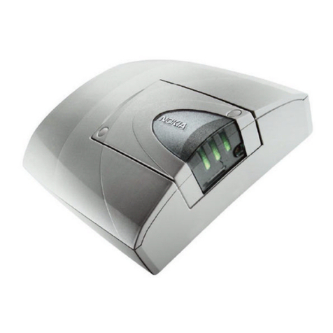
Nokia 30 GSM Installation instructions

NOKIA 30
GSM CONNECTIVITY TERMINAL
AT COMMAND GUIDE
Copyright © Nokia 2002. All rights reserved. Issue 2.0

Contents
1. INTRODUCTION..............................................................................................................2
2. DATA CONNECTIONS ....................................................................................................3
3. AT COMMAND SYNTAX..................................................................................................4
3.1 REGISTER COMMANDS ..........................................................................................4
3.2 BASIC COMMANDS..................................................................................................4
3.3 EXTENDED COMMANDS.........................................................................................5
4. TE-TA INTERFACE COMMANDS ...................................................................................6
4.1 V.25TER ....................................................................................................................6
4.1.1 S3 COMMAND LINE TERMINATION CHARACTER.............................................6
4.1.2 S4 RESPONSE FORMATTING CHARACTER......................................................6
4.1.3 S5 COMMAND LINE EDITING CHARACTER.......................................................6
4.1.4 E COMMAND ECHO..............................................................................................7
4.1.5 Q RESULT CODE SUPPRESSION.......................................................................7
4.1.6 V DCE RESPONSE FORMAT ...............................................................................7
4.1.7 X RESULT CODE SELECTION AND CALL PROGRESS MONITORING
CONTROL........................................................................................................................8
4.1.8 &C CIRCUIT 109 (RECEIVED LINE SIGNAL DETECTOR) BEHAVIOUR............8
4.1.9 &D CIRCUIT 108 (DATA TERMINAL READY) BEHAVIOUR................................8
4.1.10+IPR FIXED DTE RATE.........................................................................................9
4.1.11+ICF DTE-DCE CHARACTER FRAMING..............................................................9
4.1.12+IFC DTE-DCE LOCAL FLOW CONTROL..........................................................10
4.1.13+ILRR DTE-DCE LOCAL RATE REPORTING ....................................................10
4.2 DE FACTO...............................................................................................................11
4.2.1 S25 DETECT DTR CHANGE TIME .....................................................................11
4.2.2 &S DSR SIGNAL BEHAVIOUR............................................................................11
4.2.3 &K SELECT FLOW CONTROL............................................................................11
5. GENERIC COMMANDS.................................................................................................12
5.1 V.25TER ..................................................................................................................12
5.1.1 Z RESET TO DEFAULT CONFIGURATION........................................................12
5.1.2 &F SET TO FACTORY-DEFINED CONFIGURATION ........................................12
5.1.3 I REQUEST IDENTIFICATION INFORMATION ..................................................12

5.1.4 +GMI REQUEST TA MANUFACTURER IDENTIFICATION................................13
5.1.5 +GMM REQUEST TA MODEL IDENTIFICATION...............................................13
5.1.6 +GMR REQUEST TA REVISION IDENTIFICATION...........................................13
5.1.7 +GSN REQUEST TA SERIAL NUMBER IDENTIFICATION................................13
5.1.8 +GCAP REQUEST COMPLETE CAPABILITIES LIST........................................13
5.2 DE FACTO...............................................................................................................14
5.2.1 &V VIEW CONFIGURATION...............................................................................14
5.2.2 &W STORE CONFIGURATION...........................................................................14
5.2.3 &Y SELECT POWER-UP CONFIGURATION......................................................14
5.3 GSM 07.07...............................................................................................................14
5.3.1 +CGMI REQUEST ME MANUFACTURER IDENTIFICATION ............................14
5.3.2 +CGMM REQUEST ME MODEL IDENTIFICATION............................................15
5.3.3 +CGMR REQUEST ME REVISION IDENTIFICATION........................................15
5.3.4 +CGSN REQUEST ME SERIAL NUMBER IDENTIFICATION............................15
5.3.5 +CSCS SELECT TE CHARACTER SET .............................................................15
5.3.6 +WS46 SELECT WIRELESS NETWORK............................................................16
6. CALL CONTROL COMMANDS......................................................................................17
6.1 V.25TER ..................................................................................................................17
6.1.1 D DIAL..................................................................................................................17
6.1.2 T SELECT TONE DIALLING................................................................................18
6.1.3 P SELECT PULSE DIALLING..............................................................................19
6.1.4 A ANSWER RESPONSE.....................................................................................19
6.1.5 H HOOK CONTROL.............................................................................................20
6.1.6 O RETURN TO ONLINE DATA STATE...............................................................20
6.1.7 S0 AUTOMATIC ANSWER..................................................................................20
6.1.8 S6 PAUSE BEFORE BLIND DIALLING...............................................................21
6.1.9 S7 CONNECTION COMPLETION TIMEOUT......................................................21
6.1.10S8 COMMA DIAL MODIFIER TIME.....................................................................21
6.1.11S10 AUTOMATIC DISCONNECT DELAY...........................................................21
6.1.12L MONITOR SPEAKER LOUDNESS...................................................................22
6.1.13M MONITOR SPEAKER MODE...........................................................................22
6.1.14+DS DATA COMPRESSION................................................................................22
6.1.15+DR DATA COMPRESSION REPORTING.........................................................23
6.2 DE FACTO...............................................................................................................23

6.2.1 B CCITT/BELL MODE..........................................................................................23
6.2.2 S1 RING COUNT.................................................................................................24
6.2.3 S2 ESCAPE CODE CHARACTER.......................................................................24
6.2.4 S12 ESCAPE GUARD TIME................................................................................24
6.2.5 +++ ESCAPE .......................................................................................................24
6.3 GSM 07.07...............................................................................................................25
6.3.1 +CSTA SELECT TYPE OF ADDRESS................................................................25
6.3.2 +CMOD CALL MODE ..........................................................................................25
6.3.3 +CHUP HANG UP CALL......................................................................................26
6.3.4 +CBST SELECT BEARER SERVICE TYPE........................................................26
6.3.5 +CRLP RADIO LINK PROTOCOL.......................................................................27
6.3.6 +CR SERVICE REPORTING CONTROL ............................................................28
6.3.7 +CEER EXTENDED ERROR REPORT...............................................................28
6.3.8 +CRC CELLULAR RESULT CODES...................................................................29
6.3.9 +CHSR CURRENT CALL PARAMETERS REPORTING ....................................29
6.3.10+CSNS SINGLE NUMBERING SCHEME............................................................30
6.3.11+CHSD HSCSD DEVICE PARAMETERS ...........................................................30
6.3.12+CHSN HSCSD PARAMETER COMMAND SYNTAX.........................................31
6.3.13+CHSC HSCSD CURRENT CALL PARAMETERS.............................................32
6.3.14+CV120 V.120 RATE ADAPTION PROTOCOL...................................................33
6.3.15+CVHU VOICE HANG UP CONTROL.................................................................33
7. NETWORK SERVICE COMMANDS (GSM 07.07) ........................................................34
7.1 +CREG NETWORK REGISTRATION.....................................................................34
7.2 +COPS OPERATOR SELECTION..........................................................................35
7.3 +CLCK FACILITY LOCK..........................................................................................36
7.4 +CPWD CHANGE PASSWORD..............................................................................38
7.5 +CLIP CALLING LINE IDENTIFICATION PRESENTATION...................................38
7.6 +CLIR CALLING LINE IDENTIFICATION RESTRICTION ......................................39
7.7 +COLP CONNECTED LINE IDENTIFICATION PRESENTATION..........................40
7.8 +CCWA CALL WAITING..........................................................................................41
7.9 +CUSD UNSTRUCTURED SUPPLEMENTARY SERVICE DATA..........................42
7.10 +CSSN SUPPLEMENTARY SERVICE NOTIFICATIONS.......................................43
7.11 +CCFC CALL FORWARDING NUMBER AND CONDITIONS................................44
7.12 +CHLD CALL RELATED TO SSS ...........................................................................45

7.13 +CAOC ADVICE OF CHARGE................................................................................46
8. ME CONTROL AND STATUS COMMANDS (GSM 07.07)............................................47
8.1 +CPIN ENTER PIN..................................................................................................47
8.2 +CBC BATTERY CHARGE .....................................................................................48
8.3 +CSQ SIGNAL QUALITY.........................................................................................49
8.4 +CPBS SELECT PHONEBOOK MEMORY STORAGE..........................................49
8.5 +CPBR READ PHONEBOOK ENTRIES.................................................................50
8.6 +CPBF FIND PHONEBOOK ENTRIES...................................................................50
8.7 +CPBW WRITE PHONEBOOK ENTRY..................................................................51
9. ME ERROR COMMAND (GSM 07.07)...........................................................................53
9.1 +CMEE REPORT MOBILE EQUIPMENT ERROR..................................................53
10. SMS COMMANDS (GSM 07.05)....................................................................................54
10.1 +CSMS SELECT MESSAGE SERVICE..................................................................54
10.2 +CPMS PREFERRED MESSAGE STORAGE........................................................55
10.3 +CMGF MESSAGE FORMAT .................................................................................56
10.4 +CSCA SERVICE CENTRE ADDRESS..................................................................56
10.5 +CSMP SET TEXT MODE PARAMETERS.............................................................57
10.6 +CSDH SHOW TEXT MODE PARAMETERS.........................................................57
10.7 +CSCB SELECT CELL BROADCAST MESSAGE TYPES.....................................58
10.8 +CSAS SAVE SETTINGS........................................................................................59
10.9 +CRES RESTORE SETTINGS................................................................................59
10.10 +CNMI NEW MESSAGE INDICATIONS TO TE......................................................60
10.11 +CMGL LIST MESSAGES.......................................................................................62
10.12 +CMGR READ MESSAGE......................................................................................64
10.13 +CNMA NEW MESSAGE ACKNOWLEDGEMENT TO ME/TA...............................66
10.14 +CMGS SEND MESSAGE ......................................................................................68
10.15 +CMSS SEND MESSAGE FROM STORAGE.........................................................69
10.16 +CMMS MORE MESSAGES TO SEND..................................................................70
10.17 +CMGW WRITE MESSAGE TO MEMORY.............................................................71
10.18 +CMGD DELETE MESSAGE..................................................................................72
10.19 +CMGC SEND COMMAND.....................................................................................72
11. VOICE COMMANDS......................................................................................................75
11.1 +FCLASS DCE MODE ............................................................................................75
11.2 +VTS DTMF GENERATION....................................................................................75
12. MISCELLANEOUS COMMANDS...................................................................................76
12.1 V.25TER ..................................................................................................................76
12.1.1A/ REPEAT LAST COMMAND LINE....................................................................76
13. GPRS COMMANDS (GSM 07.07) .................................................................................77
13.1 SUPPORTED GPRS USER CONTEXT ID VALUES ..............................................77
13.2 +CGDCONT DEFINE PDP CONTEXT....................................................................77
13.3 +CGQREQ QUALITY OF SERVICE PROFILE (REQUESTED)..............................78
13.4 +CGQMIN QUALITY OF SERVICE PROFILE (MINIMUM ACCEPTABLE)............78
13.5 +CGATT GPRS ATTACH OR DETACH..................................................................78
13.6 +CGACT PDP CONTEXT ACTIVATE OR DEACTIVATE.......................................79
13.7 +CGDATA ENTER DATA STATE............................................................................79
14. FAX COMMANDS..........................................................................................................80
14.1 TIA-578-A.................................................................................................................80
14.2 TIA-592....................................................................................................................80
14.3 TIA SP-2388 ............................................................................................................82
15. RESULT CODES ...........................................................................................................84
15.1 V.25TER ..................................................................................................................84
15.1.1BASIC SYNTAX RESULT CODES......................................................................84
15.1.2+DR DATA COMPRESSION REPORT................................................................84
15.1.3+ILRR DTE-DCE LOCAL RATE REPORT...........................................................85
15.2 DE FACTO...............................................................................................................85
15.2.1CALL REPEAT RESTRICTION RESULT CODES...............................................85
15.3 GSM 07.07...............................................................................................................85
15.3.1+CSSI INTERMEDIATE SUPPLEMENTARY SERVICE NOTIFICATION...........85
15.3.2+COLP CONNECTED LINE IDENTIFICATION REPORT...................................86
15.3.3+CR DATA SERVICE REPORT...........................................................................86
15.3.4+CRING DISTINCTIVE RING ..............................................................................86
15.3.5+CLIP CALLING LINE IDENTIFICATION REPORT ............................................87
15.3.6+CSSU UNSOLICITED SUPPLEMENTARY SERVICE NOTIFICATION............87
15.3.7+CCWA CALL WAITING......................................................................................88
15.3.8+CREG NETWORK REGISTRATION..................................................................90
15.3.9+CUSD NETWORK-INITIATED UNSTRUCTURED SUPPLEMENTARY
SERVICE DATA.............................................................................................................90
15.3.10 +CME ERROR MOBILE EQUIPMENT ERROR...........................................91

15.3.11 +CHSR HSCSD PARAMETERS REPORT...................................................91
15.4 GSM 07.05...............................................................................................................92
15.4.1+CMTI NEW SMS-DELIVER INDICATION..........................................................92
15.4.2+CMT NEW SMS-DELIVER.................................................................................92
15.4.3+CBM NEW CBM.................................................................................................93
15.4.4+CDSI NEW SMS-STATUS-REPORT INDICATION...........................................94
15.4.5+CDS NEW SMS-STATUS-REPORT..................................................................95
15.4.6+CMS ERROR MESSAGE SERVICE FAILURE..................................................96
15.5 PN-3131...................................................................................................................96
15.5.1IN-BAND EVENTS FROM DCE TO DTE.............................................................96
16. ERROR VALUES ...........................................................................................................97
16.1 +CME ERROR VALUES..........................................................................................97
16.2 +CMS ERROR VALUES..........................................................................................99
17. EXAMPLE PROCEDURES ON SOME AT-COMMANDS............................................101
17.1 INPUTTING PIN CODE.........................................................................................101
17.2 INITIALISING THE NOKIA 30................................................................................102
17.3 MAKING A DATA CALL WITH NOKIA 30: ............................................................102
17.4 SENDING AN SMS FROM A TERMINAL OR OTHER SIMILAR APPLICATION..102
17.5 SENDING A SAMPLE SMS IN TEXT MODE ........................................................103
17.6 HSCSD COMMAND EXAMPLES..........................................................................103
18. CHANGE HISTORY.....................................................................................................105
19. REFERENCES.............................................................................................................106
QUESTIONS AND ANSWERS ............................................................................................107

Copyright © Nokia 2002. All rights reserved.
Reproduction, transfer, distribution or storage of part or all of the contents in this document in any form
without the prior written permission of Nokia is prohibited.
Nokia and Nokia Connecting People are registered trademarks of Nokia Corporation. Other product
and company names mentioned herein may be trademarks or trade names of their respective owners.
Nokia operates a policy of continuous development. Nokia reserves the right to make changes and
improvements to any of the products described in this document without prior notice.
Under no circumstances shall Nokia be responsible for any loss of data or income or any special,
incidental, consequential or indirect damages howsoever caused.
The contents of this document are provided "as is". Except as required by applicable law, no warranties
of any kind, either express or implied, including, but not limited to, the implied warranties of
merchantability and fitness for a particular purpose, are made in relation to the accuracy, reliability or
contents of this document. Nokia reserves the right to revise this document or withdraw it at any time
without prior notice
The availability of particular products may vary by region. Please check with the Nokia dealer nearest to
you.

2/107
1. INTRODUCTION
This document describes the AT commands that can be used to operate the Nokia 30 GSM
Connectivity Terminal.
All the mandatory and optional ITU-T V.25ter /1/, ETS GSM 07.07 /2/, and ETS GSM 07.05
/3/ commands that are applicable to the Nokia 30 are included in the Nokia 30 command set.
The 'de facto' commands that are widely used with modems are also supported. Note that
the ITU-T V.25ter is a combination of three TIA standards (TIA-602, TIA-615, IS-131).
The Nokia 30 can be used as an adapter for a Group 3 facsimile terminal that supports
facsimile Service Classes 1, 2 and 2.0. The supported facsimile AT commands are listed
according to the standards in which they are specified: Service Class 1 TIA-578-A /4/,
Service Class 2.0 TIA-592 /5/ and Service Class 2 TIA SP-2388 /6/. TIA SP-2388 is a draft of
a future standard, but here it is referred to as a public standard.
The Nokia 30 can be operated using a compatible computer or other devices with a 9-pin
RS232 connector. AT commands are also available on 3 V level on the M2M System
Connector of the Nokia 30 terminal.
For more detailed information about the Nokia 30 GSM Connectivity Terminal, other Nokia
M2M products and application development, please visit our website at
http://www.forum.nokia.com or http://www.americas.forum.nokia.com and M2M links.

3/107
2. DATA CONNECTIONS
The Nokia 30 supports non-transparent data connections. It also supports High Speed Circuit
Switched Data (HSCSD) and General Packet Radio Data (GPRS) in non-transparent mode.
Time slot usage is presented as the number of up and down links. The Nokia 30 terminal
data transfer modes are presented in Table 1.
Table 1. The Nokia 30 data transfer modes.
Data transfer mode Mode Data rate
Non-transparent data Asynchronous data 9600 kbps
Asynchronous data 14400 kbps
Asynchronous data HSCSD Multislot Class 6 (1+1, 2+1,
2+2 and 3+1)
Asynchronous data GPRS Multislot Class 6 (1+1, 1+2,
2+2 and 3+1)

4/107
3. AT COMMAND SYNTAX
For basic information on the AT command syntax, refer to section V.25ter and to GSM 07.07
section 4. This chapter describes the three different AT command formats and the default
value mechanisms for their parameters.
3.1 REGISTER COMMANDS
Table 2. Register command format in command
description subsections
Command Response <n> values
Set Sn=<n> x..y (default z)
Read Sn? <n> xxx..yyy
The register command factory default value (&F) is given in parentheses under the column
‘<n> values’. The existence of a register command can be queried by giving a command
without equal signs or question marks (i.e. ATS3 returns OK, but it does not change the <n>
setting). <n> cannot be omitted when its value is set (i.e. ATS3= returns ERROR).
3.2 BASIC COMMANDS
Table 3. Basic command format in command description subsections
Command Description
Set/ Execute CMD[x] for value x
CMDy for value y
The commands D (dial), A (answer) and O (return to online data state) also include columns
for possible result codes.
The basic command (no ‘+’ prefix) &F default value is underlined. If no value is underlined,
the setting of that command is not stored in the non-volatile memory (the command &Y is an
exception). If the command parameter is in brackets (usually zero), the parameter can be
omitted.

5/107
3.3 EXTENDED COMMANDS
Table 4. Extended command format in command description subsections
Command Response Default +cme error/+cms
error
Set/execute +CMD[=<x>,...] [+CMD: <y>,...] [x,...] [x]
Read +CMD? +CMD: <z>[,...] [x]
Test +CMD=? [+CMD: ...] [x]
The extended command (‘+’ prefix) parameter default values are given in a separate column.
If the default value is not in brackets, the default value is the &F default value of the
corresponding parameter. When such a parameter is omitted from a command, its value
remains the same as before. If the default value is in brackets, this value shall be used when
the parameter is omitted from the command line. The setting of such a parameter is not
stored in the memory. If a parameter has no default value, it must always be given.
NOTE: Voice (+V) and fax (+F) commands do not follow this format exactly.
GSM commands can also return a +CME ERROR or +CMS ERROR final result code, when
the error is related to the ME or network functionality. The last column indicates whether
these codes can be returned. The presentation of +CME ERROR can be controlled with the
+CMEE command.

6/107
4. TE-TA INTERFACE COMMANDS
4.1 V.25TER
4.1.1 S3 Command line termination character
Command Response <n> values
Set S3=<n> 0..127 (default 13)
Read S3? <n> 000..127
The S3 command sets the decimal IA5 value of command line termination used by the DCE
as a part of the header, trailer and terminator for result codes and information text, along with
the S4 parameter (see the description of the V command for usage).
If the value of S3 is changed on a command line, the result code issued in response to that
command line will use the new value of S3. For example, if S3 was previously set to 13 and
the command line “ATS3=50” is issued, the result code issued will use the character with the
ordinal value 50 (IA5 3/2) in place of the CR.
4.1.2 S4 Response formatting character
Command Response <n> values
Set S4=<n> 0..127 (default 10)
Read S4? <n> 000..127
The S4 command sets the decimal IA5 value of the character generated by the DCE as a
part of the header, trailer and terminator for result codes and information text, along with the
S3 parameter (see the description of the Vcommand for usage).
If the value of S4 is changed in a command line, the result code issued in response to that
command line will use the new value of S4.
4.1.3 S5 Command line editing character
Command Response <n> values
Set S5=<n> 0..127 (default 8)
Read S5? <n> 000..127

7/107
The S5 command sets the decimal IA5 value of the character recognised by the DCE as a
request to delete the immediately preceding character from the command line.
4.1.4 E Command echo
Command Description
Set E[0] No echo
E1 Echo
The E command determines whether or not the DCE echoes characters received from the
DTE during the command state and the online command state.
4.1.5 Q Result code suppression
Command Description
Set Q[0] Transmit codes
Q1 Suppress codes
The Q command determines whether the DCE transmits result codes to the DTE. When
result codes are being suppressed, no portion of any intermediate, final or unsolicited result
code – header, result text, line terminator, or trailer – is transmitted. Information text
transmitted in response to commands is not affected by this command.
4.1.6 V DCE response format
Command Description
Set V[0] Numeric V.25ter basic syntax result codes, limited headers and trailers
V1 Verbal V.25ter basic syntax result codes, full headers and trailers
The V command determines the contents of the header and trailer transmitted with result
codes and information responses. It also determines whether the result codes are
transmitted in numerical or verbal format. The text portion of information responses is not
affected by this setting. The command S3 and S4 settings affect header and trailer
formatting. Note that the result codes defined in GSM 07.07 and 07.05 only have verbal
values.

8/107
4.1.7 X Result code selection and call progress monitoring control
Command Description
Set X[0] OK, CONNECT, RING, NO CARRIER, ERROR codes enabled
X1 Also CONNECT 1200, CONNECT 2400 enabled
X2 Same as value 1
X3 Also BUSY enabled
X4 Also NO ANSWER enabled
X5 Also CONNECT 4800 (or higher data rates), CARRIER, DELAYED,
BLACKLISTED enabled
The X command defines the call progress result codes that are sent from the Nokia 30
terminal to the DTE. When BUSY, NO ANSWER, DELAYED or BLACKLISTED are not
enabled, so NO CARRIER is used instead. When CONNECT <rate> with a correct data
<rate> is not enabled, CONNECT is used instead. This command only affects the
presentation of the result codes mentioned in this table.
4.1.8 &C Circuit 109 (received line signal detector) behaviour
Command Description
Set &C[0] Always on
&C1 Normal operation
The &C command determines how the state of circuit 109 relates to the detection of a
received line signal from the remote end. Changing the parameter will take effect
immediately in both command and online command states.
In the &C1 mode of operation, circuit 109 is on during the connection. Circuit 109 is also
known as a DCD or carrier signal.
4.1.9 &D Circuit 108 (data terminal ready) behaviour
Command Description
Set &D[0] DTR on->off ignored
&D1 DTR on->off causes transition to online command state if a call is in progress
&D2 DTR on->off causes hang up
&D3 DTR on->off causes hang up and performs reset, like Z
The &D command determines how the DCE responds when circuit 108/2 is changed from
ON to OFF during the online data state. Circuit 108 is also known as the DTR signal.

9/107
4.1.10 +IPR Fixed DTE rate
Command Response Default
Set +IPR=<rate> 0
Read +IPR? +IPR: <rate>
Test +IPR=? +IPR:
(0,1200,2400,4800,9600,14400,192
00,28800,38400,57600,115200), ()
The +IPR command sets the data rate at which the DCE will accept commands. The
specified rate takes effect immediately following the issuance of the current command line.
NOTE: The reset commands Z and &F do not change this setting.
Defined values
<rate> is the bit transmission rate per one second
4.1.11 +ICF DTE-DCE character framing
Command Response Default
Set +ICF=<format>,
<parity> [0,3]
Read +ICF? +ICF: <format>,<parity>
Test +ICF=? +ICF: (0-6),(0-3)
The +ICF command is used to determine the local serial port start-stop character framing
that the Nokia 30 uses when accepting DTE commands and when transmitting information
text and a result.
NOTE: The reset commands Z and &F do not change this setting.
Defined values
<format> determines the number of bits in the data bits, the presence of a parity bit, and
the number of stop bits in the start-stop frame.
0 auto detect
1 8 data, 2 stop
2 8 data, 1 parity, 1 stop
3 8 data, 1 stop
4 7 data, 2 stop

10/107
5 7 data, 1 parity, 1stop
6 7 data, 1 stop
<parity> determines how the parity bit is generated and checked, if present.
0 odd
1 even
2 mark
3 space
The parity can be set only for format values 2 and 5.
4.1.12 +IFC DTE-DCE local flow control
Command Response Default
Set +IFC=<dce-by-dte>,<dte-by-dce> 2,2
Read +IFC? +IFC: <dce-by-dte>,<dte-by-dce>
Test +IFC=? +IFC: (0-3),(0-2)
The +IFC controls the operation of local flow control between the DTE and the Nokia 30.
Defined values
<dce-by-dte>specifies the method to be used by the DTE to control the flow of received data
from the Nokia 30
<dte-by-dce>specifies the method to be used by the Nokia 30 to control the flow of
transmitted data from the DTE
0 No flow control
1 Software flow control (XON/XOFF)
2 Hardware flow control (RTS/CTS)
3 Software flow control (XON/XOFF), with flow control characters
also passed to the remote DCE
4.1.13 +ILRR DTE-DCE local rate reporting
Command Response Default
Set +ILRR=<n> 0
Read +ILRR? +ILRR: <n>
Test +ILRR=? +ILRR: (0,1)
The +ILRR command controls whether the extended-format “+ILRR:<rate>” information text
is transmitted from the Nokia 30 to the DTE. The <rate> reported represents the current

11/107
DTE-DCE rate. If enabled, the intermediate result code is transmitted after any error control
or data compression reports are transmitted and before any final result code (i.e. CONNECT)
is transmitted.
4.2 DE FACTO
4.2.1 S25 Detect DTR change time
Command Response <n> values
Set S25=<n> 0..255 (default 0)
Read S25? <n> 000..255
The S25 command sets the time in seconds for reacting to the DTR signal change. The
value 255 inhibits the signal change recognition. See also the &D command.
4.2.2 &S DSR signal behaviour
Command Description
Set &S[0] Always on
&S1 No effect
The &S command is ignored, the DSR is always ON.
4.2.3 &K Select flow control
Command Description
Set &K[0] No flow control
&K3 Hardware flow control (RTS/CTS)
&K4 Software flow control (XON/XOFF)
The &K command changes the same setting as the +IFC. The use of +IFC is recommended.

12/107
5. GENERIC COMMANDS
5.1 V.25TER
5.1.1 Z Reset to default configuration
Command Description
Execute Z[0] reset to stored profile 0
Z1 reset to stored profile 1
The settings that are not stored in a profile (refer to &W) will be reset to their factory defaults
(refer to &F). The implementation is according to GSM 07.07 section 5.7.
5.1.2 &F Set to factory-defined configuration
Command Description
Execute &F[0] reset to factory defaults
This command instructs the Nokia 30 to set default values to all parameters. The command
parameters that are reset to their factory defaults are: S3, S4, S5, E, Q, V, X, &C, &D, +IFC,
+ILRR, S25, &S, +CSCS, S0, S7, S8, S10, +DS, +DR, S2, S12, +CSTA, +CMOD, +CBST,
+CRLP, +CR, +CRC, +CSNS, +CREG, +COPS (only <format>), +CLIP, +CLIR, +COLP,
+CCWA (only <n>), +CUSD (only <n>), +CSSN, +CMER, +CPBS, +CMEE, +CSMS,
+CPMS, +CMGF, +CSCA, +CSMP, +CSDH, +CSCB, +CNMI.
5.1.3 I Request identification information
Command Response Description
Execute I[0] Nokia Mobile Phones same as +GMI
I1 IMEI same as +GSN
I2 Vx.xx dd-mm-yy TME-3 © NMP same as +GMR
I3 Nokia 30 same as +GMM
I4..I13 Ignored values

13/107
5.1.4 +GMI Request TA manufacturer identification
Command Response
Execute +GMI Nokia Mobile Phones
5.1.5 +GMM Request TA model identification
Command Response
Execute +GMM Nokia 30
5.1.6 +GMR Request TA revision identification
Command Response
Execute +GMR Vx.xx dd-mm-yy TME-3 © NMP
5.1.7 +GSN Request TA serial number identification
Command Response
Execute +GSN IMEI
5.1.8 +GCAP Request complete capabilities list
Command Response
Execute +GCAP +GCAP: +CGSM, +FCLASS, +DS +W
Defined values
+CGSM This is not a command to be used, but it refers to the support of the GSM 07.07 AT
command set. Implementation is according to GSM 07.07 section 5.7.
+FCLASS A command to query the support of different facsimile classes
+DS Data Compression
Other manuals for 30 GSM
1
Table of contents
Other Nokia Touch Terminal manuals

Nokia
Nokia DNT2Mi-fp User manual

Nokia
Nokia 32 User manual

Nokia
Nokia Mobile Phone User manual

Nokia
Nokia DNT2Mi sp/mp User manual

Nokia
Nokia 7368 User manual

Nokia
Nokia XS-2426G-A User manual

Nokia
Nokia 7368 User manual

Nokia
Nokia XS-010X-Q User manual

Nokia
Nokia SERIES 30 User manual

Nokia
Nokia Cardphone 2.0 User manual