NOMA 052-8687-4 User manual

Gunnar Ceiling Fan
OWNER’S MANUAL
model no. 052-8687-4
Toll-free 1-866-827-4985
IMPORTANT:
For your safety, please read and understand
this manual before installing or operating this product.

Warning: To risk of personal injury, do not bend the blade arms (also referred to as flanges) or the brackets while
balancing the blades or cleaning the fan. Do not insert foreign objects between rotating fan blades.
Warning:
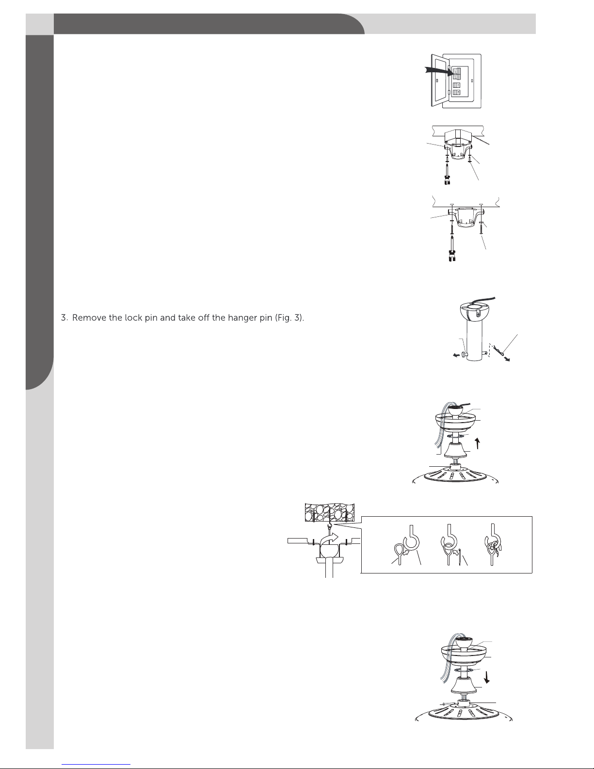
for fan support” with the screws provided with the outlet box.
To reduce the risk of fire, electric shock, and personal injury, mount fan to outletbox marked ”acceptable
Safety Rules – Read and Save These Instructions
before beginning.
2. All wiring must be in accordance with the national and local electrical codes. Electrical installation should
be performed by a qualified licensed electrician.
3. WARNING: To reduce the risk of electric shock or fire, do not use this fan with any solid-state fan-speed
control device. It will permanently damage the electronic circuitry.
4. CAUTION: To reduce the risk of personal injury, use only the screws provided with the outlet box.
5. The outlet box and support structure must be securely mounted and capable of reliably supporting a
minimum of 35 lb (15.9 kg). Use only UL listed outlet boxes marked “FOR FAN SUPPORT.”
6. The fan must be mounted with a minimum of 7' (2.13 m) from the trailing edge of the blades to the
floor.
7. Avoid placing objects in the path of the blades.
8. To avoid personal injury or damage to the fan and other items be cautious when working around or
cleaning the fan.
9. Do not use water or detergents when cleaning the fan or fan blades. A dry dust cloth will be suitable for
most cleaning.
10. After making electrical connections, spliced conductors should be turned upward and pushed carefully
up into the outlet box. The wires should be spread apart with the grounded conductor and the
equipment-grounding conductor on one side of the outlet box and the ungrounded conductor on the
other side of the outlet box.
11. All set screws must be checked and retightened where necessary
before installation.
Warning: To reduce the risk of fire, electric shock, or personal injury, mount to outlet box marked "acceptable for
fan support of 35 lb (15.9 kg) or less" and use mounting screws provided with the outlet box. Most outlet boxes
commonly used for the support of light fixtures are not acceptable for fan support and may need to be replaced.
Due to the complexity of this fan, a qualified licensed electrician is strongly recommended.
!
!
!
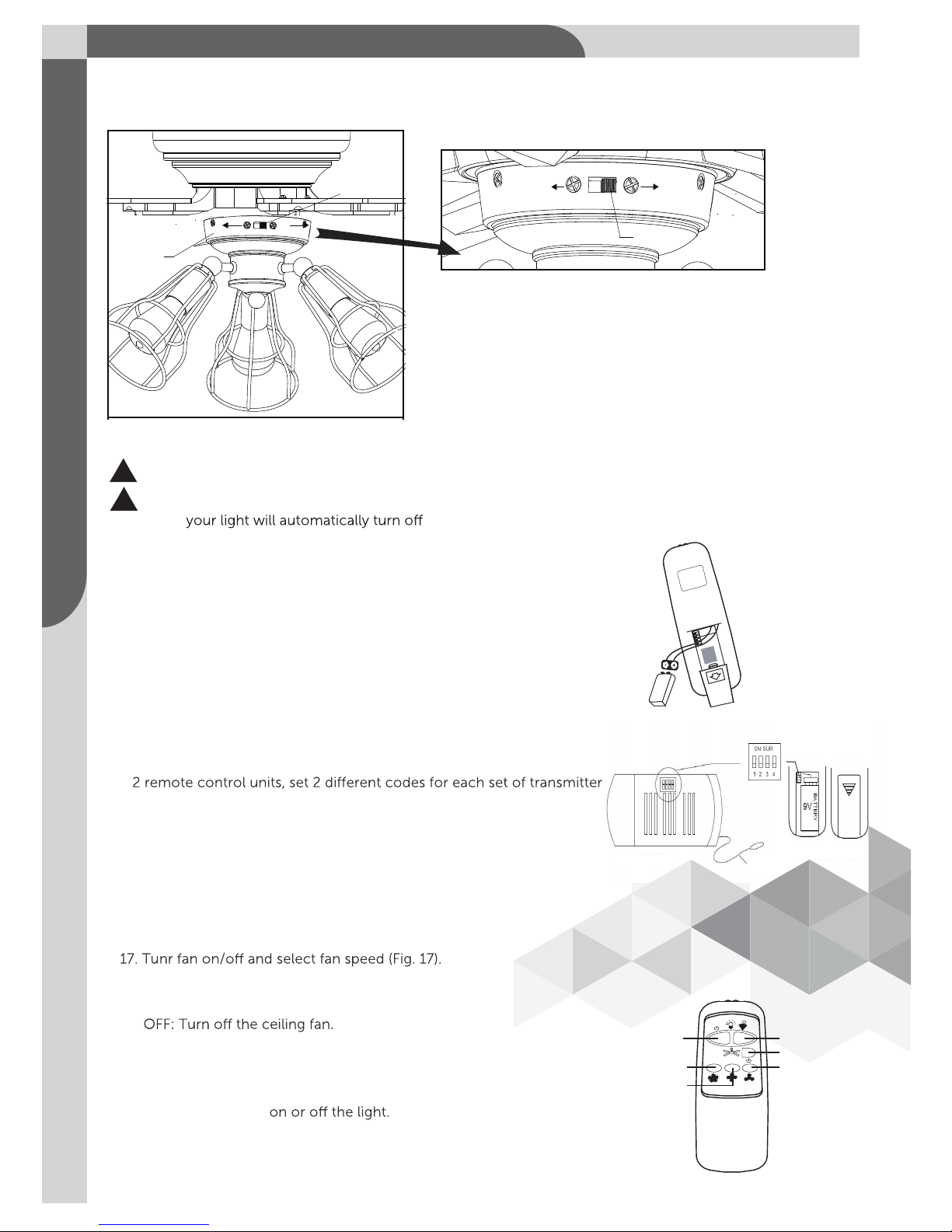
Attention: This product is equipped with a 190 W limiting device. If lamping exceeds 190 W the light kit will shut
bulbs with the correct wattage, and then turning the light kit back on.
!
IMPORTANT: RETAIN FOR FUTURE REFERENCE, AND READ CAREFULLY.
Toll Free 1-866-827-4985 model no. 052-8687-4

3
1
Required
Helpful
Flathead
screwdriver
Crosshead
screwdriver
Safety glasses
Pliers Step ladder
Wire strippers
Wire cutters
Soft cloth
Electrical tape
To Beging: Tools Needed (not supplied)
To prevent personal injury and damage, ensure
that the hanging location allows the blades a
clearance of 7' (2.13 m) from the floor and 30"
(76 cm) from any wall or obstruction.
This fan can be mounted with a downrod on a regular
(no-slope) or vaulted ceiling. Other installations,
such as flush mount, are not available for this fan.
downrod
installation
flush mount
installation
vaulted ceiling
angle is not to
exceed 15°.
7’
(2.13 m)
30”
(76 cm)

3
2
Unpack your fan and check the contents. You should have the
following items.
1.) Hanger Bracket
2.) Canopy
3.) Canopy Cover
4.) Downrod Stand Cover
5.) Downrod Set (Included Hanger Ball,
Downrod, Hanger Pin & Lock Pin)
6.) Fan Motor Assembly
7.) Blade Brackets (5PCS)
8.) Fan Blades (5PCS)
9.) Switch Box Cover
10.) Switch Box
11.) Light Kit
12.) ST 48 Bulb Max 60 W (3PCS)
13.) Blade Balancing Kit
14.) Installation Instructions
15.) Remote Control
1
17.) Parts pack containing
6.) Receiver
Exploded View Detail
Package Contents:
5
9
1
6
34
2
13
X16
14 15
12
10
11
Installation
Instruction
7
8
Light Kit
Switch Box Cover
Switch Box
ST 48 Bulb Max 60 W
Hanger Bracket
Canopy
Downrod
Downrod Stand Cover
Hanger Ball
Hanger Pin
Blade Holder
Canopy Cover
Collar
Lock Pin
Fan Blade
Fan Motor Assembly
17
Parts pack containing:
2 wood screws with flat washers
2 5/32”-screws with lock washers
1 extra blade bracket screw
with spring washer
16 blade screws with washer
1 “J” hook
1 zip tie
16
Toll Free 1-866-827-4985 model no. 052-8687-4

3
Safety Instructions
To reduce the risk of injury, install the fan so that the blades are at least 7' (2.1 m) above the floor
and at least 18" (0.5 m) from the tip of the blades to the wall.
To reduce the risk of fire, electric shock, or personal injury, mount to outlet box marked "ACCEPTABLE FOR
FAN SUPPORT" and use mounting screws provided with the outlet box.
The installation must be in accordance with the national electrical code, ANSI/NFPA 70-1999 and local codes.
If you are unfamiliar with the methods of installing electrical wiring, seek the services of a qualified licensed
electrician.
Making the Electrical Connections
Warning: To avoid risk of electric shock, be sure to shut o power at the main fuse or circuit bracker box
before installing or servicing this fixture. Turning o the electrical power by using the light switch is not
sucient to prevent electric shock.
!
Warning : To reduce the risk of fire, electric shock, or personal injury, mount to outlet box and use
mounting screws provided with the outlet box.
!
!
!
NOTE: The fan weight is 17 lb 13 oz (8.1 kg). Be sure the outlet box you are using is securely attached to the
building structure and can support the full weight of the fan. Failing to do so can result in serious injury.
Read all safety information and installation instructions before you begin to install the fan
and save instructions.
1. All set screws of the fan must be checked and retightened where necessary before installation.
2. To reduce the risk of personal injury, do not bend the blade brackets when installing the
brackets, balancing the blades or cleaning the fan. Do not insert foreign objects between
rotating fan blades.
4. The safeguards provided by these safety instructions and by the separate installation
instructions are not meant to cover all possible conditions and situations that may occur. It must
be understood that common sense, caution and care are factors which can not be built into this
product. These factors must be supplied by the person(s) installing, caring for and operating the
fan.
Making the Electrical Connections
3. Before changing the fan direction, turn o the fan and wait for the fan blades to stop completely.
IMPORTANT: Before you begin installing the fan, carefully read all information on the separate sheet “SAFETY
INSTRUCTIONS” as well as the following “INSTALLATIONS” . If in doubt, consult a qualified electrician.
Save all instructions.

4
1.
2. (1) Securely attach the mounting bracket to an outlet box marked
“Acceptable for Fan Support ”, using the supplied outlet box screws
with spring washers (Fig. 2a).
(2)
Securely attach the mounting bracket to the ceiling, using
the two sets of long wood screws with flat washers (Fig. 2b).
4. Thread the motor wires and safety cable through the downrod stand cover, canopy
cover, canopy and downrod (Fig. 4a).
For added security attach safety cable from fan unit to “J” hook in outlet
box. Secure by looping zip tie through safety cable and “J” hook. Tighten
zip tie securely ( Fig. 4b).
5. Insert the downrod into the collar. Slide hanger pin through holes of collar and
downrod (Fig. 5).
Installation Steps :
Turn OFF the electric circuit at the main fuse or circuit breaker box (Fig. 1).
Fig. 1
Fig. 2a
Hanger Pin
Lock Pin
Fig. 3
Motor Wires
Downrod
Downrod Stand
Cover
Canopy Cover
Canopy
Collar
Fig. 4a
Collar
Downrod
Hanger Pin
Canopy
Canopy Cover
Downrod Stand
Cover
Fig. 5
Mounting
Bracket Outlet Box
Spring Washer
Outlet Box Screw
Mounting
Bracket
Flat Washer
Wood Screw
Fig. 2b
Drill two mounting holes in the ceiling joist.
“J” hook zip Tie
Fig. 4b
Safety
Cable
Toll Free 1-866-827-4985 model no. 052-8687-4

Once the connection has been made, the receiver inserts into the drop rod hanging
bracket. The canopy comes up to cover the receiver and bracket (Fig. 16).
5
!
6. Insert and tighten the two collar screws. Slide lock pin into hanger
pin until it is locked into position (Fig. 6).
7. Hang the fan on hanger bracket, and make sure the slot of hanger ball
is snapped into the chip of hanger bracket exactly (Fig. 7).
Lock Pin
Collar Screws
Slot
Ch
ip
Hanger Bracket
Fig. 6
Fig. 7
IMPORTANT : If you are not sure if the electrical outlet box and fan are grounded, contact a licensed
electrician for advice. They must be grounded for safe opetration.
!
!
8. Wiring instructions
!
!
!
·
WARNING:
before wiring.
!
!

6
!
!
!
Between fan and receiver :
. Connect the black wire marked ”L” from the fan to the black wire marked “TO MOTOR L” from the receiver.
. Connect the blue wire marked ”FOR LIGHT” from the fan to the blue wire marked “FOR LIGHT” from the
receiver.
. Connect the wire marked ”N” from the fan to the wire marked “TO MOTOR N” from the receiver.
Between receiver and mains:
. Connect the black live wire marked ”AC IN L” from the receiver to the live wire (typicalolly black) from
the outlet box.
. Connect the white neutral wire marked ”AC IN N” from the receiver to the neutral wire (typically white)
from the outlet box.
. Connect the green ground wire from the mounting bracket and hanger ball to the ground wire bare
from the outlet box.
Outlet box
(Mains cables)
Ground wire
Green ground
wire from mounting
and hanger ball
AC IN L
LAC D’IN
AC IN
AC D’IN
TO MOTOR N
AU MOTEUR DEN
TO MOTOR L
AU MOTEUR DEL
FOR LIGHT
POUR LA LUMIERE
N
L
FOR LIGHT
hanger ball green ground wire
Hanger
Bracket
Hanger
Ball
Receiver
Antenna:
DO NOT CUT
OR SPLICE
9. Half-tighten two hanger bracket screws, then push the canopy upwards and let
the hanger bracket screw heads come through the key hole slot, then rotate the
canopy counter-clockwise until canopy is secured. Now, tighten hanger bracket
screws. Finally, push the canopy cover upward, then turn it counter-clockwise
until it is secure (Fig. 9).
Canopy Screw
Key Hole
Slot
Canopy
Canopy Cover
Fig. 9
Hanger bracket
Screw
Hanger Bracket
Toll Free 1-866-827-4985 model no. 052-8687-4
N
N
or green
bracket

7
!
!
10. Tighten fan blades to blade brackets by using blade screws
and washers (Fig. 10).
11. Secure blade brackets to the motor with motor screws
and washers (Fig. 11).
. If there are plastic tabs shaped like bottle caps, remove and
discard them. These are stabilizers that protect the motor
durping shipping.
Remove blade bracket screws on the bottom of the motor
and use them to attach the blade assembly to the motor
and tighten the screws.
12. Remove one fix screw (for later use), and loosen the other
two fix screws. Thread the wire through the switch box
cover, and then push the switch box cover upwards by
inserting the other two fix screw heads into key hole slots,
rotate the switch box cover till the round hole in switch
box cover aligns with the hole in motor assembly, and finally,
secure the switch box cover to motor assembly with previous
fix screw and tighten the other two fix screws (Fig. 12).
13. Attach the switch box to light kit and secure them with a washer
and a hex nut (Fig. 13).
14. Connect wires: (Fig. 14)
Connect the blue (live) wire from the switch box to the black
(hot) wire from fan light with a wire nut.
Connect the white (neutral) wire from the switch box to the
white (neutral) wire from fan light with a wire nut.
Carefully put the wires into the switch box. Then connect
the two terminals respectively from the motor and the
switch box.
Remove three screws from switch box cover.
Secure the switch box to motor with three switch box screws.
Install bulbs (included). See relamping label at socket
area or packaging for maximum allowed wattage.
Fig. 10
Fig. 11
Fig. 12
Light Kit
Switch Box
Hex Nut
Washer
Fig. 13
Fig. 14
Fan Blade
Blade Screw
W
asher
Blade Bracket
Blade Bracket
Motor Screw
Switch Box
Cover
Key Hole Slot
Round Hole
Fix Screw
Motor
Assembly
Switch Box
Screw
ST 48 Bulb Max 60 W
(Included)
Terminals
Light Kit
Wire Nut

8
15. The slide switch on switch box sets direction of fan rotation. Select the desired direction of fan rotation.
Push the slide switch left for “Forward” and right for "Reverse" (Fig. 15).
Slide Switch
Forward Reverse
Fig. 15
!
NOTE:Wait for fan to stop before reversing the direction of blade rotation.
Fig. 15
Switch Box
Slide Switch
Forward Reverse
Restore power to the ceiling fan and test for proper operation.
16. Install the 9Vs battery (included). To prevent damage to transmitter,
remove the battery if not used for long periods (Fig. 16).
· Restore power to ceiling fan and test for proper operation.
· The fan remote control controls the fan setting:
HI: Turn on the fan at high speed.
MED: Turn on the fan at medium speed.
LOW: Turn on the fan at low speed
LIGHT: ON/OFF: Press and release immediately to turn
Operating Your Transmitter
Fig. 16
9V
Battery
DIMMER: Press and hold on to dim or brighten
lights to the desired level and release
(only for tungsten bulbs).
LIGHT
ON /OFF
HI
MED
DIMMER
FAN OFF
LOW
Fig. 17
!
NOTE:Your fan has an energy-saving wattage limiter. If wattage exceeds 190 W,
Ensure bulb wattage is always below 190 W.
!
CODE SWITCH
· CODE SWITCH: Codes are set by pushing dip switches up or down.
It is imperative that the code used for both transmitter and receiver
is exactly the same; otherwise remote
controller will not work.
· Your remote control is ready for use after battery installation.
RECEIVER ANTENNA
TO OPEN BATTERY
HOUSING COVER
PRESSS DOWN
AND SLIDE OUT.
controller independently. For example, if you have two ceiling fans with
DIP SWITCH
Please note the code switch will enable you to operate a second remote
/receiver. This will enable you to operate each ceiling fan independently.
TRANSMITTER
Toll Free 1-866-827-4985 model no. 052-8687-4

9
!
.
18. Turn on the electric circuit at the main fuse or circuit breaker box (Fig. 18).
Fig.18
PROBLEM SUGGESTED REMEDY
1. If fan does not start:
2. If fan sounds noisy:
3. If fan wobbles:
4. If light does not work:
1. Check main and branch circuit fuses or circuit breakers.
2. Make sure forward/reverse switch is firmly in left or right position. Fan will
not operate when switch is in the middle.
3. Make sure that the wall control is turned "ON".
4. Check line wire connections to fan and switch wire connections in switch
housing.
1. Make sure all screws in motor housing are snug (not over tightened).
2. Make sure the screws which attach the fan blade bracket to the motor are
tight.
3. Make sure wire nut connectors in switch housing are not rattling against each
other or against the interior wall of the switch housing.
4. If using an optional ceiling fan light kit, make sure the screws securing
the glassware are finger-tight. Make sure light bulb is tight in socket and
not touching glass shade(s). If vibration persists from glass, remove glass and
install a 1/4"-wide. Wide rubber band on glass neck to act as an insulator.
Replace glass and tighten screws against rubber band.
5. Some fan motors are sensitive to signals from solid state variable speed
controls. DO NOT USE a solid state variable speed control.
6. Allow "break-in" period of 24 hours. Most noises associated with a new fan
will disappear after this period.
All blades are weighed and grouped by weight. Natural woods vary in density
which could cause the fan to wobble even though all blades are weight-matched.
The following procedures should eliminate most of the wobble. Check for
wobble after each step.
1. Check that all blades are screwed firmly into blade brackets.
2. Check that all blade brackets are tightened securely to motor.
3. Make sure that canopy and hanger bracket are tightened securely to ceiling
junction box and junction box is mounted firmly to ceiling joist.
4. Most wobble problems of fan are caused when blades are not in equal level.
To check the blade levels, select a point on the ceiling above the tip of any
blade. Measure the distance from the ceiling to the blade tip, to an accuracy
of 1/8" (3 mm). Rotate the blades until the next blade is in the measuring
position. Repeat measurement for each blade. If all blade levels are not equal,
you can adjust blade levels by the following procedure. To adjust a
blade tip down, insert a washer (not supplied) between the blade and
blade bracket at thescrew closest to the motor. To adjust a blade tip up,
insert washer (not supplied) between the blade and blade bracket at the two
screws farthest from the motor.
5. Interchanging two adjacent blades could redistribute the weight and possibly
result in smoother operation.
1. Check blue wire from fan to make sure it is connected to hot wire from supply
wire coming out of the ceiling.
2. Check for loose or disconnected wires in fan switch housing.
3. Check for loose or disconnected wires in light kit.
4. Check for faulty light bulbs.

10
!
!
!
PREFACE
Your ceiling fan may sometimes have wobbling problems when operating due to irregularity in the
blades or the blade holders. Improper assembly in the mounting systemmay cause some additional
problems. This balancing kit can be used to fix wobbling problems.
DYNAMIC BLADE BALANCING KIT FOR CEILING FANS
1. Make sure that all blades are firmly screwed into the blade holder.
2. Make sure that all blade holders are firmly secured to the motor housing and check that the pitch of blade
holders
are all the same..
3. By looking up at the fan from below, check and be certain that none of the blade holders are bent and that
none of the blades are out of position.
4. Use a yardstick to check the blade tracking. Put the yardstick up against the ceiling vertically and against the
outside leading edge of a blade. Note the distance of the edge of blade to the ceiling. Carefully turn the
blades slowly by hand to check the remaining blades. If the blade is not in alignment, the blade holder may
be gently bent up or down to be in line with the other blades.
After following all the steps and if the wobbling problem is not solved, a dynamic balancing needs
to be done by balancing kit. Follow the procedure listed below:
●
halfway between the blade holder and the blade tip on the edge of the blade.
Caution: The plastic clip should be placed on the windward edge of the blade to avoid
●Turn the fan on (use the speed that causes the wobble most). Observe if the wobble is better or
on which blade the clip reduces the wobble most. Place the clip on the blade which showed the
most improvement. Move the clip inward and outward on this blade and operate the fan to find
the position where the clip gives the most improvement.
Caution: Stay clear of the blades. If the clip, for any reason, is not secure, injury could result.
● Once the exact position is determined, place a weight on the top of the blade, on its centreline and
it is securely attached to the blade. Remove the clip.
Caution: Clean the surface of fan blade before placing the balancing weight so that the balancing
weight can be firmly attached on it.
!
!
!
!
!
DYNAMIC BLADE BALANCING KIT
BALANCING WEIGHT
MEASURING
POINT
YARDSTICK
PLASTIC CLIP
CENTRELINES
COUNTER-
CLOCKWISE
1
2
3
4
5
6
7
8
9
worse. Turn the fan o and move the clip to the next blade. Do the same for all blades and note
Toll Free 1-866-827-4985 model no. 052-8687-4

11
.
Here are some suggestions to help you maintain your fan.
1. Because of the fan's natural movement, some connections may become loose. Check the support
connections, brackets, and blade attachments twice a year. Make sure they are secure. (It is not
necessary to remove fan from ceiling bracket.
2. Clean your fan periodically to help maintain its new appearance over the years. Use only a soft brush or
lint-free cloth to avoid scratching the finish. The plating is sealed with a lacquer to minimize discolouration
This could damage the motor, the wood, or possibly cause an
electric shock.
3. You can apply a light coat of furniture polish to the wood blades for additional protection and enhanced
beauty. Cover small scratches with a light application of shoe polish.
4. There is no need to oil your fan. The motor has permanently lubricated sealed ball bearings.
PROBLEM
Fan will not start
Fan sounds noisy
Lights shut o
and will not
come back on.
SOLUTION
Check main and branch circuit fuses or breakers.
Check line wire connections to the fan and switch wire connections in the switch housing.
Make sure all motor housing screws are snug.
Make sure the screws that attach the fan blade bracket to the motor hub are tight.
Make sure wire nut connections are not ra
the switch housing.
Allow a 24-hour "breaking-in" period. Most noises associated with a new fan disappear
during this time.
If using ceiling fan light kit, make sure the screws securing the glassware are tight.Check
that the light bulb is also secure.
Make sure there is a short distance from the ceiling to the canopy. It should not touch the
ceiling.
Make sure your ceiling box is secure and rubber isolator pads are used between
mounting bracket and outlet box.
ttling against each other or the interior wall of
This unit is equipped with a wattage limiting device. Lamping in excess of 190 W will
disable your ceiling fan's light kit. To reset your light kit you
to your ceiling fan and continue normal operation.
box before you attempt any repairs.
This product carries a limited ten (10) year warranty against defects in the motor, and a one (1) year
warranty against defects in workmanship and materials. Noma Canada agrees to replace the defective product
free of charge within the stated warranty period, when returned by the original purchaser with proof of purchase.
This product is not guaranteed against wear or breakage due to misuse and/or abuse.
Made in China
Imported by
Noma Canada, Toronto, Canada M4S 2B8
Refer to the section, "making electrical connections".
!
Care of Your Fan
Trouble shooting
Warranty
or tarnishing. Do not use water when cleaning.
and install bulbs of lower wattage, keeping the wattage under 190 W. Restore power
Table of contents
Other NOMA Fan manuals

NOMA
NOMA MILTON 052-9717-8 User manual

NOMA
NOMA 052-8398-2 User manual

NOMA
NOMA Lakeside 52" User manual

NOMA
NOMA 052-9340-2 User manual

NOMA
NOMA 052-9299-2 User manual

NOMA
NOMA 043-5641-2 User manual

NOMA
NOMA 043-7026-6 User manual

NOMA
NOMA Miles User manual

NOMA
NOMA 043-5221-2 User manual

NOMA
NOMA Alabaster User manual

NOMA
NOMA 052-9339-8 User manual

NOMA
NOMA 043-7023-2 User manual

NOMA
NOMA 052-9335-6 User manual

NOMA
NOMA 052-4744-2 User manual

NOMA
NOMA 052-1196-4 User manual

NOMA
NOMA 043-6169-2 User manual

NOMA
NOMA Quatra 052-9329-2 User manual

NOMA
NOMA 043-7018-6 User manual

NOMA
NOMA ASHTON User manual

NOMA
NOMA Landon User manual