9
4.3 WING SENSOR INSTALLATION
1. Assemble the Breakaway Sensor Mounting
Brackets (B11) as show in Figure 4 and
Figure 5.
Figure 4 – Breakaway Sensor Bracket
Exploded View
Figure 5 – Breakaway Sensor Mounting
Bracket Assembly
To assemble the breakaway sensor bracket:
a) Assemble the bolt and nut into the collar.
b) Grease the bottom edge of the collar and
the angled tube of the base.
c) Place the collar onto the angled tube of
the mounting base.
d) Install the spring between the collar and
the upper ring of the base.
e) Insert tube through assembly and tighten
the collar
2. Mount the sensor bracket onto the boom.
If possible, mount the sensor brackets
while the booms are in their folded
position to ensure that they will not
interfere with anything when the boom
is folded for transport.
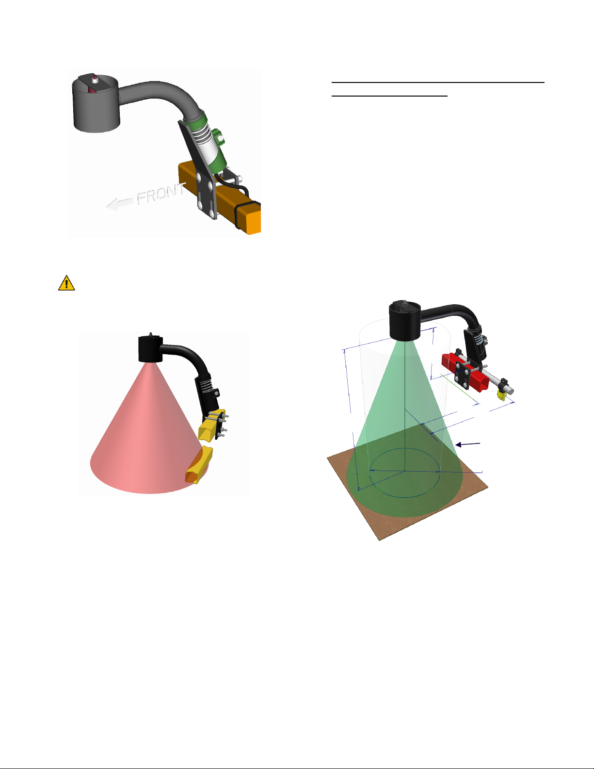
3. The sensor mounting brackets can be
installed with the mounting base behind
(Figure 8) or in front of the tube (Figure 6).
It is advised to avoid mounting the
sensor bracket to a breakaway portion
of the boom because a breakaway
action can cause the UC4+ Spray
Height Control system to force a boom
close to the ground.
Please refer to the UC4+ Spray Height
Control system warranty at the end of the
UC4+ Spray Height Control Operator’s
Manual (M01) for implications.
4. Mount the NORAC UC4+ ultrasonic sensor
(E02) into the sensor brackets. The sensors
should be oriented forward (ahead) of the
boom (see Figure 6 and Figure 8).
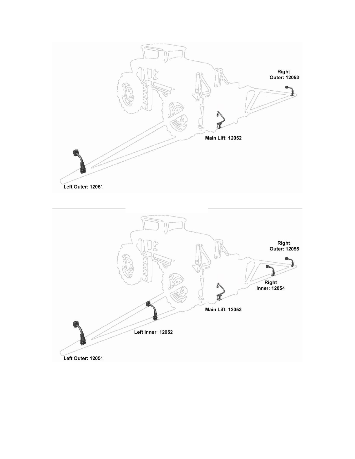
When installing the UC4+ sensors
(E02), start with the smallest serial
number on the left hand side
proceeding to the largest serial number
on the right hand side (Figure 9).
5. Sensor cables should run through the
mounting bracket tube and then behind the
member the bracket is mounted onto. Cable-
tie the connector in place. The cable must
not be allowed to hang below the boom
(Figure 6).