E3G-L1/L3 E3G-L1/L3
7
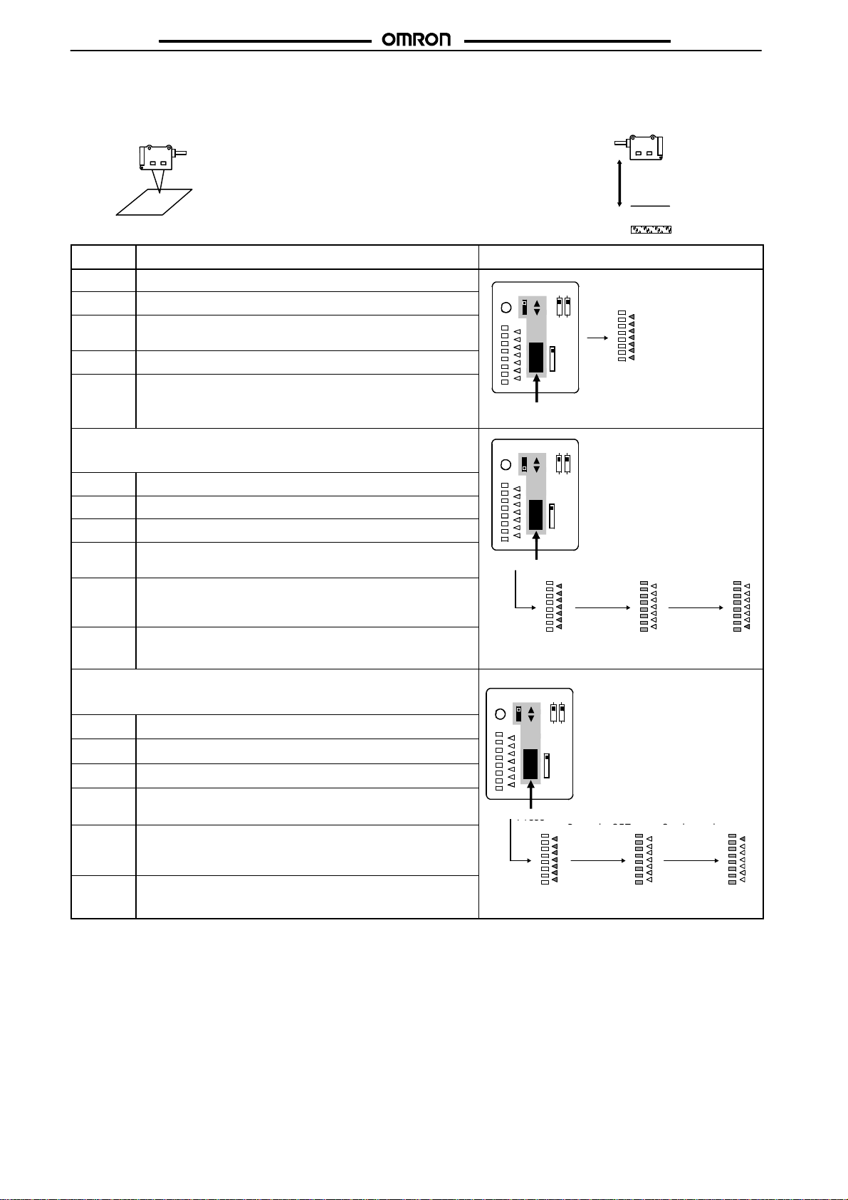
Nomenclature
UP/DOWN selector
Selects the switching direction
at threshold.
Operation indicator (Orange)
ON when output is ON.
Distance indicator (Green)
Display the distance relative to
the threshold.
Threshold indicator (Red)
Indicates threshold level.
For teaching or for threshold adjustment
Operation mode selector
Selects L-ON or D-ON.
NORMAL/ZONE selector
Selects the detection mode.
Mode selector
Selects the mode.
NORM L
ZONE D
ADJ
FAR
SET TEACH
OUT
RUN
SET button
NEAR
Installation
Designing
Do not pull cables with tensile strength exceeding 50 N for the
cable pull-out or connector types.
High-tension Lines
Do not wire power lines or high-tension lines alongside the lines of
the Sensor in the same conduit, otherwise the Sensor may be
damaged or may malfunction due to induction. Be sure to wire the
lines of the Sensor separated from power lines or high-tension
lines or laid in an exclusive, shielded conduit.
Turning the Power ON
The Sensor needs 100 ms to be ready to operate after it is turned
ON. The devices connected to the Photoelectric Sensor must wait
until the Sensor is ready to operate. If the Sensor and load are
connected to separate power supplies, be sure to turn ON the
Sensor first.
Power Supply
If a standard switching regulator is used, be sure to ground the FG
(frame ground) and G (ground) terminals, otherwise the Sensor
may malfunction due to the switching noise of the regulator.
Wiring
Cable
The bending radius of the cable should be 25 mm min.
In a case where the cable is extended, use a wire with 0.3 mm2
min. The total length of the cable should be 100 m max.
Avoiding Malfunctions
If using the photoelectric sensor with an inverter or servomotor, be
sure to ground the FG (frame ground) and G (ground) terminals,
otherwise the Sensor may malfunction.
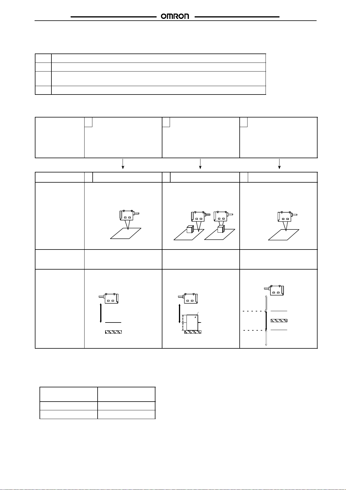
Mounting
Mounting Conditions
If Sensors are mounted face-to-face, make sure that no optical
axescrosseachother. Otherwise, mutualinterferencemayresult.
Be sure toinstall the Sensor carefully so that the directional angle
range of the Sensor will not be directly exposed to intensive light,
such as sunlight, fluorescent light, or incandescent light.
Do not strike the Photoelectric Sensor with a hammer or any other
toolduringtheinstallationoftheSensor,ortheSensorwilllooseits
water-resistive properties.
Use M3 screws to mount the Sensor.
When mountingthe case, make sure that thetightening torque ap-
plied to each screw does not exceed 0.54 N m.
M8 Connector
Be sure to connect or disconnect the M8 connector after turning
OFF the Sensor.
Be sure to hold the connector cover when connecting or discon-
necting the M8 connector.
Secure the M8 connector by hand. Do not use any pliers, other-
wise the connector may be damaged.
If the M8 connector is not connected securely, the M8 connector
may be disconnected by vibration or the proper degree of protec-
tion of the Sensor may not be maintained.