Noraxon PL1 User manual

Portable Lab Quick Start Guide
1
(Rev B)
Portable Lab
Quick Start Guide
Portable Lab Quick Start Guide
2
(Rev B)
Welcome from Noraxon
Congratulations on acquiring your new Portable Lab System!
This guide will provide you with step-by-step instructions on how to install your new
hardware, adjust device settings, and record your first data set.
Let us begin by walking through the installation of your new hardware.
Note: This is not meant to be a complete manual, but a guide to help you get started with your system. For
more detailed instructions on operating any of the systems (Ultium, DTS, Research PRO) within the Portable
Lab refer to the appropriate user manual.
1System Unboxing
Upon arrival, carefully remove all contents and verify the following components are present.
Contents will vary depending on the purchased package.
1.1 PL1 System
Figure 1 - Portable Lab
Figure 2 –PSU9
Figure 3 - USB cables (CBL33)

Portable Lab Quick Start Guide
3
(Rev B)
1.2 PL2 System
Figure 1 - Portable Lab
Figure 2 –PSU9
Figure 3 - USB cables
Portable Lab Quick Start Guide
4
(Rev B)
1.3 Ultium Portable Lab System
Figure 1 - Portable Lab
Figure 2 –PSU9
Figure 3 - USB cables

Portable Lab Quick Start Guide
5
(Rev B)
2Hardware Installation
Note: Hardware installation is shown for the first-, second-, and third-generation Portable Labs. Be sure to
follow the correct installation instructions for your system.
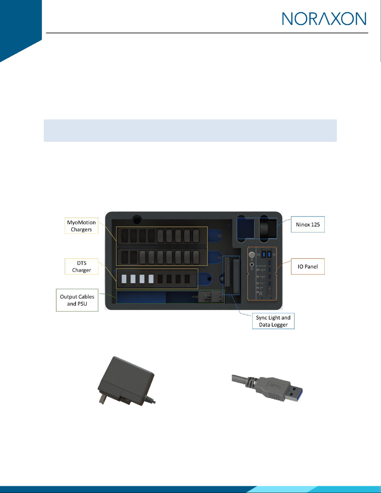
2.1 PL1 Hardware Setup Instructions
The first-generation Portable Lab System includes Research PRO (or Clinical) IMU and DTS EMG sensors
with optional Ninox 125 cameras.
Input/Output Panel
Note: Connect ONLY Ninox 125 cameras to the input/output panel. The IO panel for the PL1 is not
compatible with Ninox 300C cameras. If applicable, please connect Ninox 300C cameras directly to the
USB 3 or USB C ports on the PC.

Portable Lab Quick Start Guide
6
(Rev B)
Connection to Host Computer
Portable Lab Quick Start Guide
7
(Rev B)
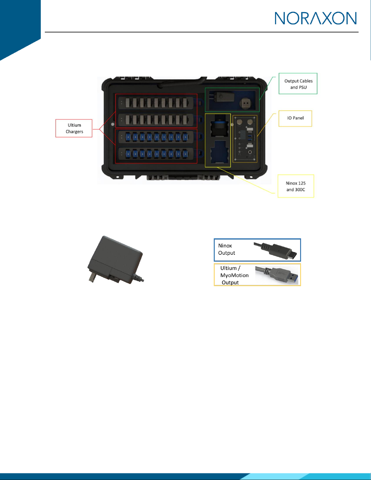
2.2 PL2 Hardware Setup Instructions
The second-generation Portable Lab System includes Research PRO (or Clinical) IMU and Ultium EMG
sensors with optional Ninox 125 and 300C cameras.
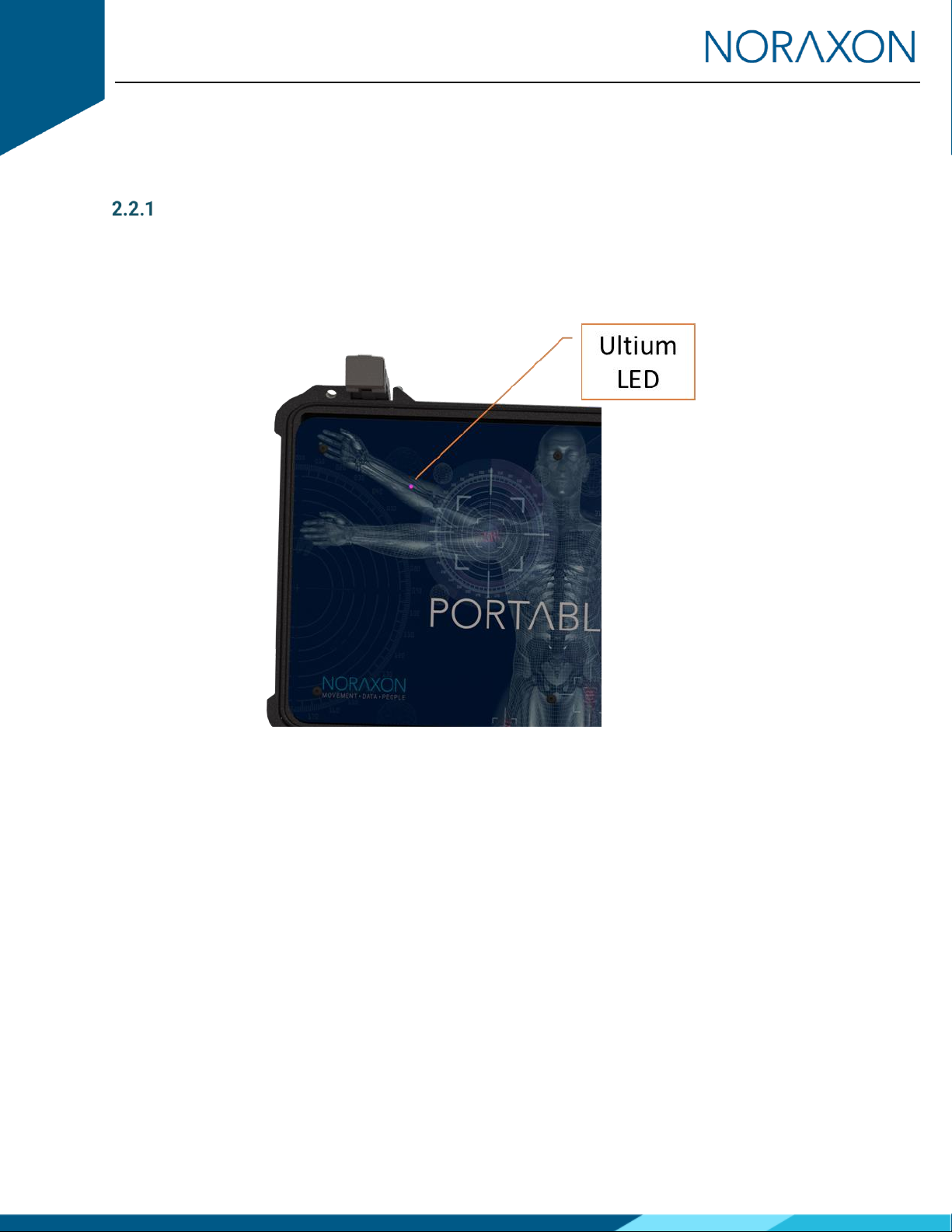
Ultium Receiver
The Ultium receiver is embedded directly into the lid of the PL2 system. The LED indicator for the Ultium
system can be viewed as shown on the PL2 lid. The LED indicator will blink PURPLE instead of the normal
blue color. The change in color signifies a PL2 Ultium receiver. All other LED color representations are
unchanged.
Portable Lab Quick Start Guide
8
(Rev B)
Input/Output Panel
Note: The Ninox Input can be used with both Ninox 125 and Ninox 300C cameras.

Portable Lab Quick Start Guide
9
(Rev B)
Connection to Host Computer
Note: It is recommended to connect the Ninox Output cable to the host computer before connecting the
Ninox cameras to the Ninox Input on the PL2 IO panel.
Ultium
Output
Portable Lab Quick Start Guide
10
(Rev B)
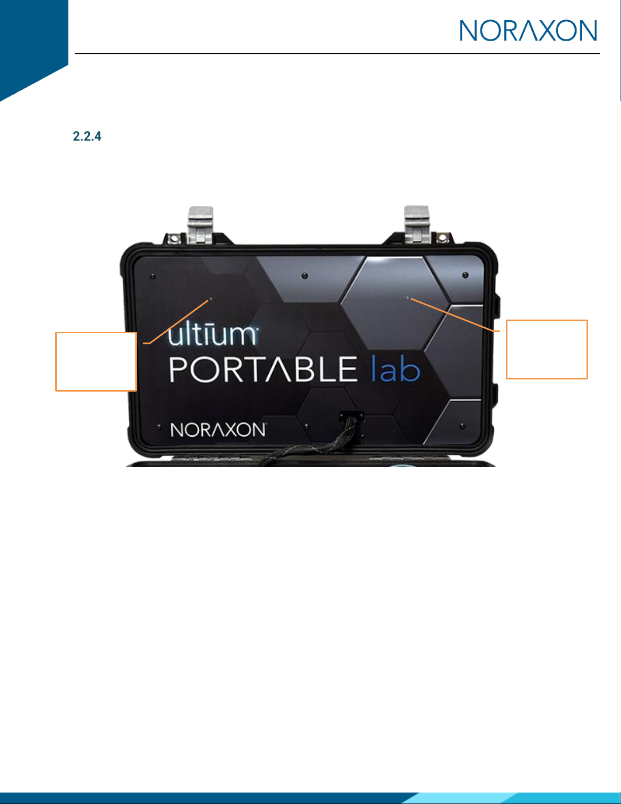
Ultium Portable Lab Hardware Setup Instructions
The third-generation Portable Lab System includes Ultium Motion and EMG sensors with optional Ninox
125 and 300C cameras.
Ultium Receiver(s)
Two Ultium receivers are embedded directly into the lid of the Ultium Portable Lab system. The LED
indicator for each Ultium system can be viewed as shown on the Ultium Portable Lab lid. The LED indicator
will blink BLUE instead of the normal solid blue LED. The change in LED behavior signifies a Ultium Portable
Lab receiver. All other LED color representations are unchanged.
Ultium
Receiver 1
LED
Ultium
Receiver 2
LED

Portable Lab Quick Start Guide
11
(Rev B)
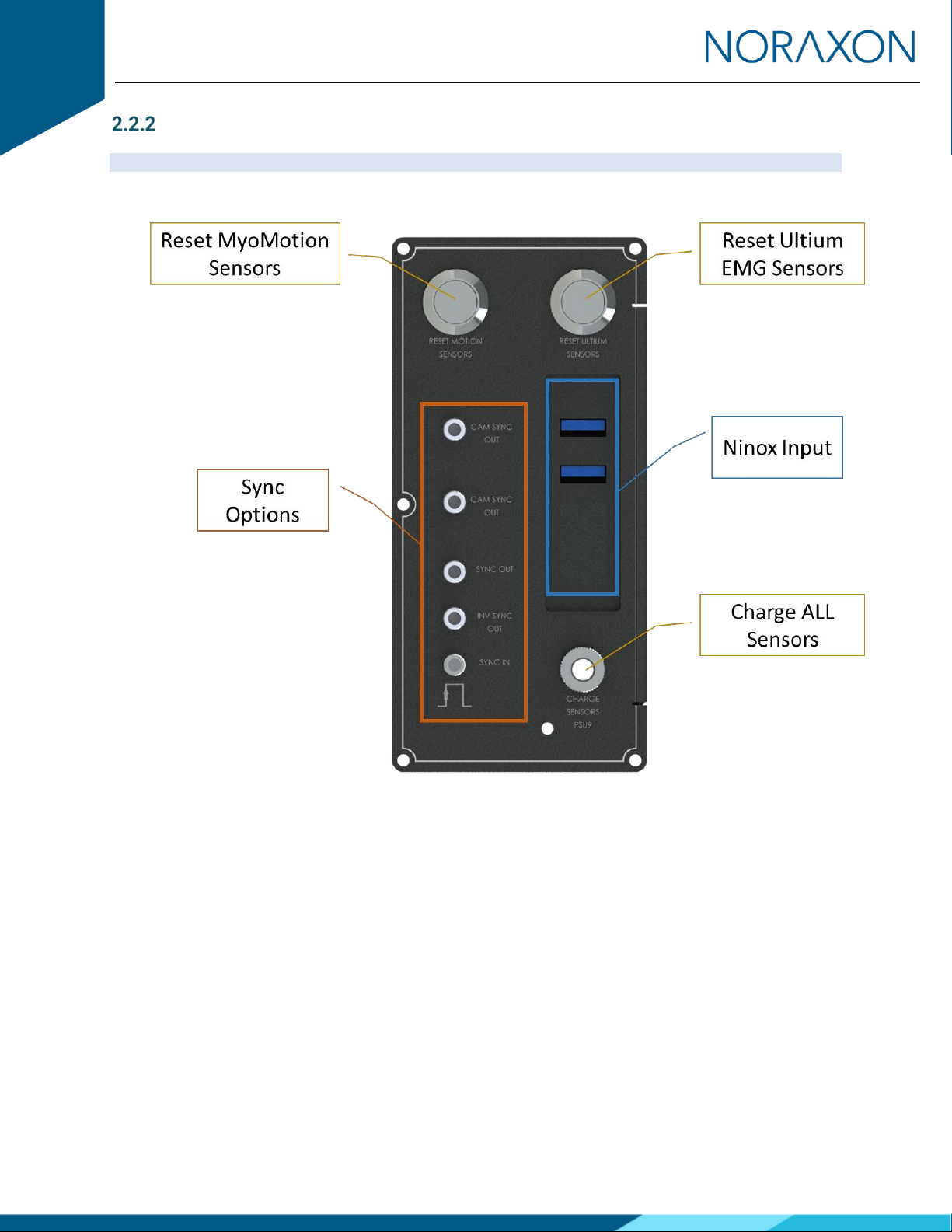
Input/Output Panel
Note: The Ninox Input can be used with both Ninox 125 and Ninox 300C cameras.
Reset Ultium
Receiver 1
Reset Ultium
Receiver 2

Portable Lab Quick Start Guide
12
(Rev B)
Connection to Host Computer
Note: It is recommended to connect the Ninox Output cable to the host computer before connecting the
Ninox cameras to the Ninox Input on the PL2 IO panel.
Ultium
Output
Portable Lab Quick Start Guide
13
(Rev B)
3Adjusting your Computer Settings
All changes to the computer settings must be made by a user with Administrator privileges.
Note: All computers may not have every Power Option listed below. Adjust only the settings available on
your computer.
Power Options
Before using the Portable Lab, the host computer must have the correct power and performance options
set.,
A note for laptop users: Be sure to change the settings for both On Battery and Plugged In modes. Be
aware that the settings are all “High Performance” and will reduce the battery run-time.
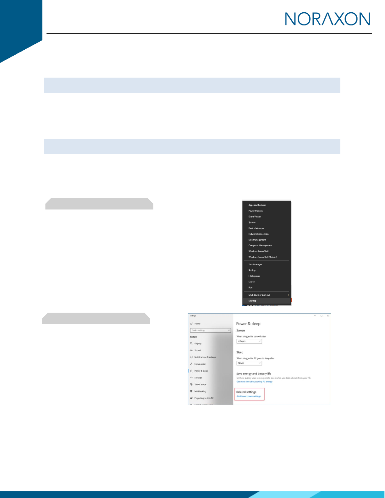
Step 1
Open the control panel by right clicking on the
Start menu and clicking on Power Options.
Step 2
Navigate to the Additional power settings

Portable Lab Quick Start Guide
14
(Rev B)
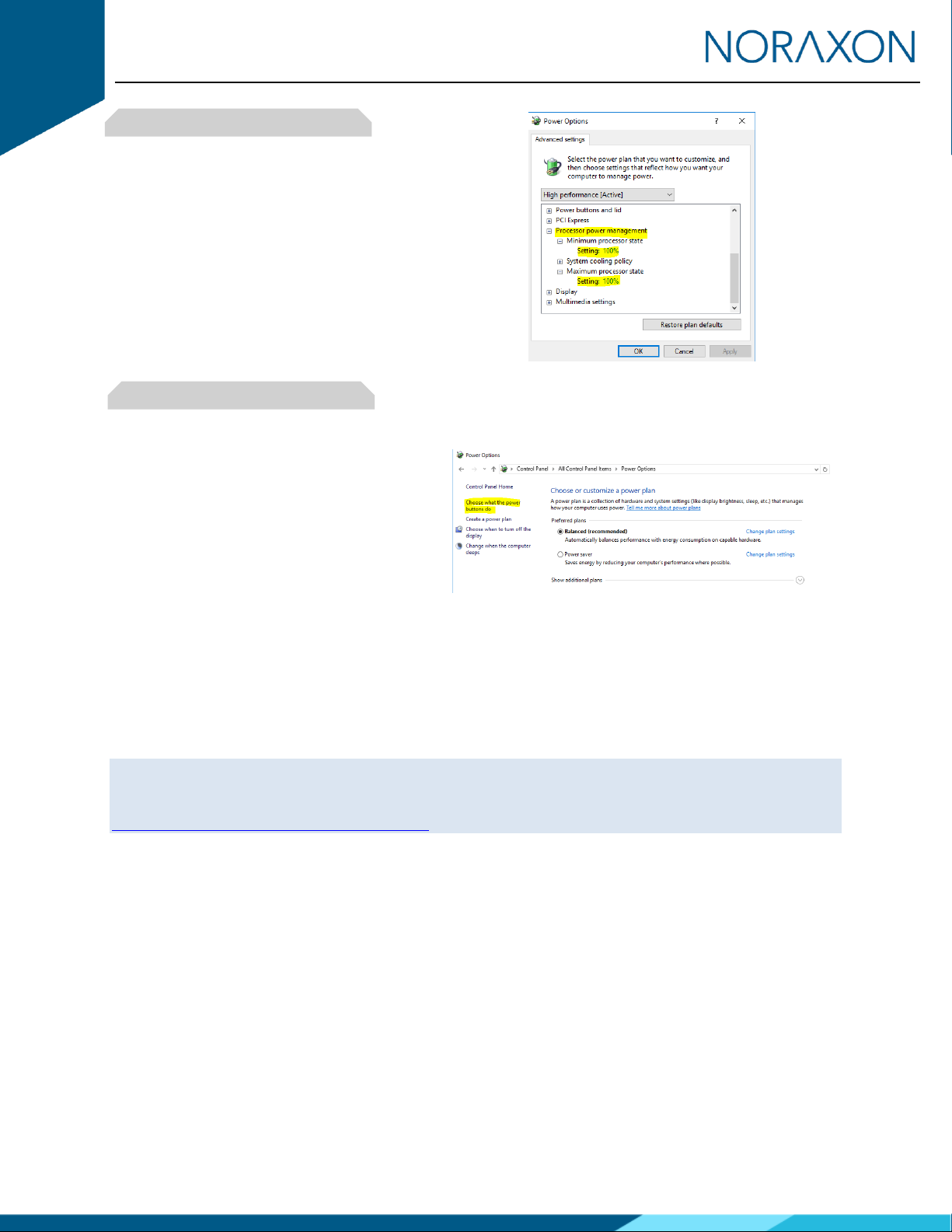
Step 3
Click on Change Plan Settings to make further
changes
Step 4
Click on Change Advanced Power Settings
Step 5
Find the USB Settings -> USB Selective
Suspend menu and select Disabled
Step 6
Find the Intel (R) Graphics Settings
Expand the Intel (R) Graphics Power Plan and
change the setting to Maximum Performance
Portable Lab Quick Start Guide
15
(Rev B)
Step 7
Find the Processor Power Management
Change both the Minimum and Maximum
Processor State to 100%
Step 8
Disable fast startup:
Open Control Panel\Power Options and click
Choose what the power buttons do on the left-
hand side.
If there is a checkbox labeled Turn on fast
startup, uncheck this box. (If this option is
gray or disabled, click the text at the top
labeled “Change settings that are currently
unavailable.”)
Graphics Card Driver
The latest graphics card drivers need to be installed on the host computer to ensure proper function with
the 3D graphics and video in MR3.
Note: The following steps are based on updating your graphics card driver through Windows. If your
computer has a Nvidia graphics card it is best to download the latest driver directly from the Nvidia
website. Install the driver following the Nvidia instructions.
https://www.nvidia.com/Download/index.aspx

Portable Lab Quick Start Guide
16
(Rev B)
Step 1
Open the Device Manager by right clicking the
start menu and select Device Manager
Step 2
In the Device Manager expand the tab labeled
Display Adapters.
Force each display adapter (graphics card) that
is listed the driver should be updated to the
latest version available.
Right click on the display adapter and select
Update Driver Software.
Step 3
Select the option to Search automatically for
updated driver software.
Step 4
If the latest drive is already installed, you will
receive the message “The best driver software
for your device is already installed”.

Portable Lab Quick Start Guide
17
(Rev B)
4Installing the Companion Software - myoResearch™ 3
To utilize the full functionality of the Portable Lab system, and ensure the system has updated drivers,
Noraxon’s myoResearch 3 (MR3) needs to be installed on the computer.
4.1 Software Installation
Within the package the Portable Lab system was shipped in, there is a USB flash drive containing the latest
myoResearch 3 software.
1. Insert the MR3 USB flash drive into the PC
2. A menu will automatically pop up
3. Click on the Noraxon installation file to begin the installation wizard
4. After installation, an icon will be created on the desktop
4.2 Companion Software Activation
The installed companion software must be activated before unrestricted use is possible.
1. Open MR3
2. A dialog box will indicate how many more times MR3
can be opened
3. Click on “Activate”
4. Enter the License ID provided on your USB flash drive
and press “OK”
5. If you have an internet connection, click Activate by
Internet for immediate activation
6. Alternatively, email the provided activation ID to
activation@Noraxon.com Noraxon Support will email
or respond by phone with the Activation Code. Enter
the provided Activation Code to remove any restrictions on use.
Portable Lab Quick Start Guide
18
(Rev B)
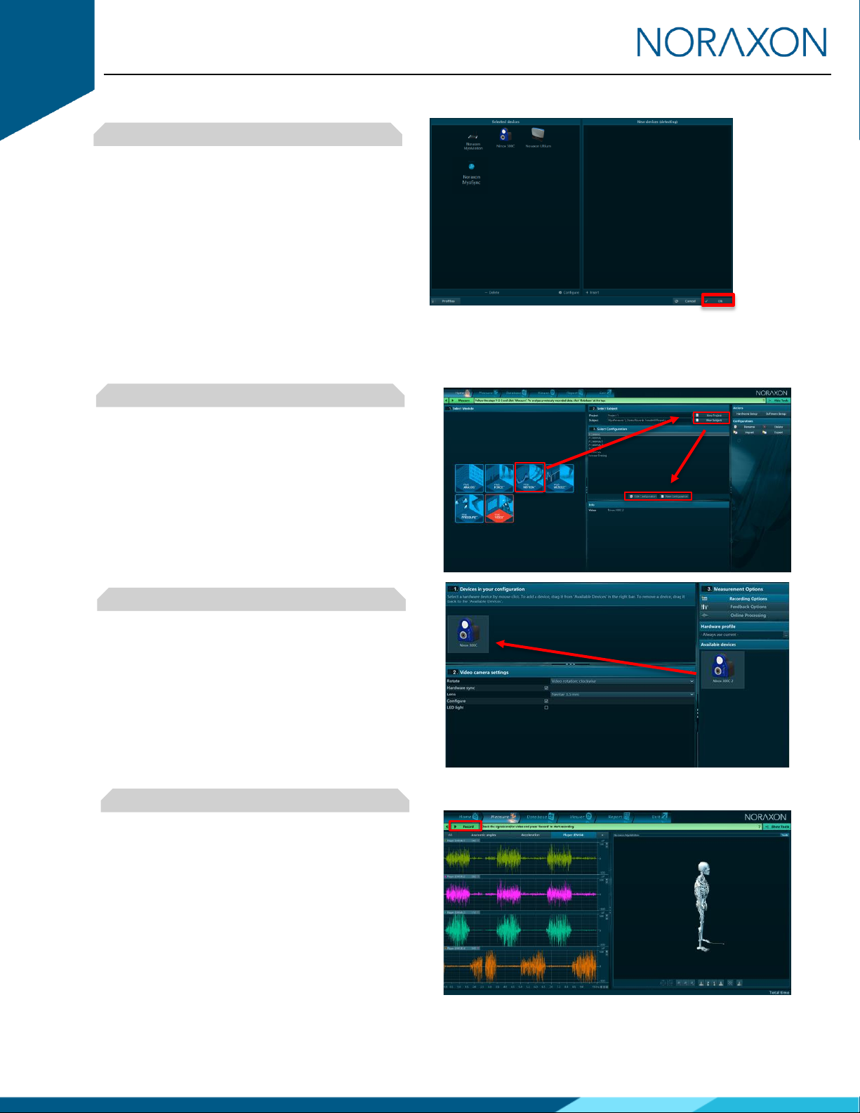
5Configuring the Hardware
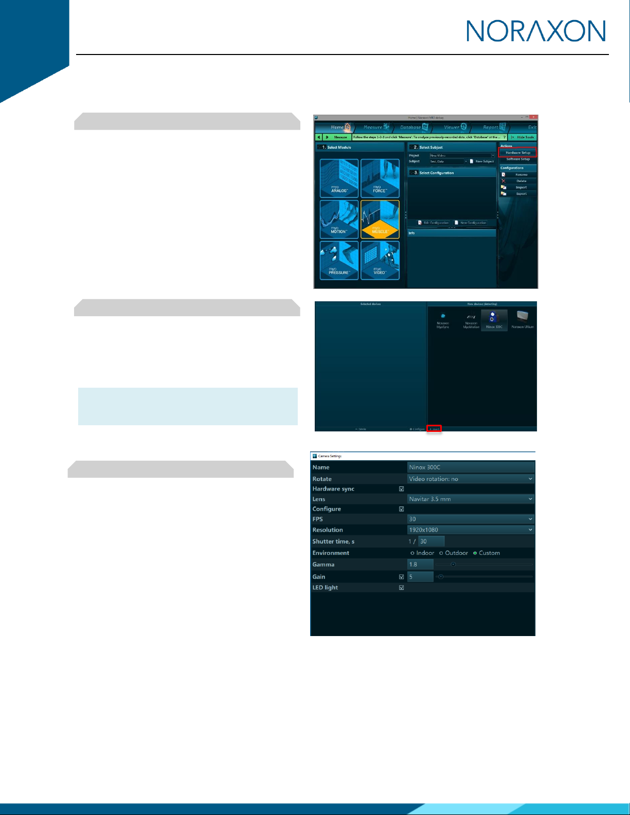
Step 1
Open MR3, typically listed under Noraxon ->
MR3
Click on the Hardware Setup button in the upper
right-hand corner.
Step 2
Insert Hardware:
Select the desired hardware icon to insert,
within the ‘New Device’ column, and click on the
Insert button. Repeat for each hardware item.
Note: Be sure to include the MyoSync icon to
synchronize all hardware included in the
measurement.
Step 3
After each hardware item is inserted, a Settings
dialog will appear as shown. Adjust the settings
as necessary.
Refer to the user manual for each hardware item
for a detailed description of the settings.
MyoMotion User Manual
Ultium EMG User Manual
Ninox User Manual
Portable Lab Quick Start Guide
19
(Rev B)
Step 4
Click on OK (in the bottom of the dialog box)
when done.
6Recording a Measurement
Step 1
Within the Home screen, click on the myoMOTION
(or myoMuscle/myoVideo) module icon.
Create a New Subject
Select New Configuration.
Step 2
Insert the devices to be used for the measurement
into the configuration by dragging a device in from
the list of Available Devices.
You may configure each hardware item here. Refer
to the appropriate user manual for information on
these settings.
Continue to the next step by selecting Measure.
Step 3
After checking for normal operation, you are ready
to record a measurement. Select Record at the top
left of the screen and begin your protocol.
After completing your record, select Stop and Save.
Save the record as the name of your configuration,
or type in a new name. After this, save your record
or Discard & measure again.

Portable Lab Quick Start Guide
20
(Rev B)
7Viewing a Record
To view a previously recorded record, select the Database tab. Records are organized by Project and
Subject name. Double click on the record of interested to open the record in the Viewer tab.
8Additional MR3 Features & Technical Support
There are many additional features built within MR3. Such as:
•EMG analysis
•Motion analysis
•2D video tracking
•Customized reporting
•Exporting (and importing) of data
To learn more about the features available to you through the system(s) you have purchased, refer to the
MyoResearch User Manual and the corresponding Hardware User Manual for this device. If for any reason
you find our support content to be insufficient for your needs, please reach out to our support team directly
by submitting a support request on our website.
9Contact Us
Noraxon U.S.A. Inc.
15770 North Greenway-Hayden Loop, Suite 100
Scottsdale, Arizona 85260
Tel: 480-443-3413
Fax: 480-371-2754
Domestic Toll Free: 800-364-8985 (US/Canada only)
International: (Use Distributor list on website)
E-mail: info@noraxon.com
This manual suits for next models
2
Table of contents
Other Noraxon Laboratory Equipment manuals


Popular Laboratory Equipment manuals by other brands


Esco
Esco ETS-Lindgren GTEM! 5411 installation manual

VERDER
VERDER Carbolite Gero HT 5/350 Installation, operation and maintenance instructions

ThermoFisher Scientific
ThermoFisher Scientific QuantStudio 6 Pro user guide

PolyScience
PolyScience MX-CA11B Operator's manual

REPLIGEN
REPLIGEN CTech FlowVPE Maintenance Guide

Safex
Safex Tintschl Engineering FlowMarker instruction manual