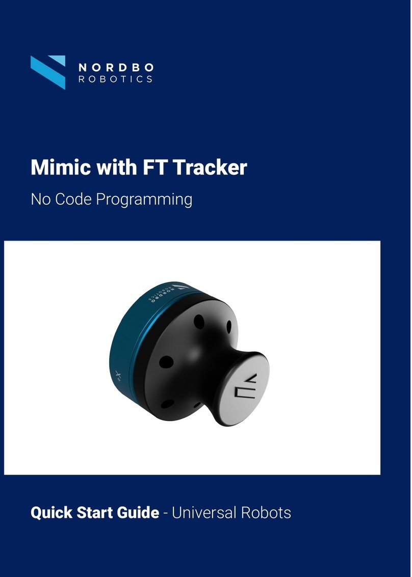
Nordbo Robotics Mimic User manual

1 of 66
Mimic Kit for Universal Robots - User Manual – Ver. 2.3
Copyright
Copyright © 2021 Nordbo Robotics. All Rights Reserved. No part of this manual may be reproduced
or transmitted in any form or by any means, electronic or mechanical, including photocopying and
recording, for any purpose without the written permission of Nordbo Robotics.
Disclaimer
The information provided in this documentation contains general descriptions of the use, of one or
more of Nordbo Robotics’ products. Following this document's instruction for installation and use
must not be considered a substitute for making a risk assessment and testing the specific application
and setup. Neither Nordbo Robotics nor any of our affiliates or subsidiaries shall be held responsible
for the consequences that arise from misuse of – or misunderstanding of – any information stated in
this document.
If any instructions are considered unclear it is the user’s responsibility to contact Nordbo Robotics
for clarification of the issue(s) before making use of said unclear instructions.
If the user has any suggestions for improvements, amendments, or if errors have been found in this
release, please notify Nordbo Robotics.
Nordbo Robotics reserves the right to make refinements or changes without notice.
Warranty
Warranty void if products are opened. The warranty further excludes failure resulting from improper
use or installation, normal wear and tear, abuse, accidents, neglect, fire, water, lightning, or other acts
of nature, causes external to the product, or other factors beyond Nordbo’s control.
Contact
Nordbo Robotics A/S
Noatunvej 2
5000 Odense, Denmark
Phone: +45 81 81 98 81
Mail: info@nordbo-robotics.com

2 of 66
Mimic Kit for Universal Robots - User Manual – Ver. 2.3
Table of Contents
1. Introduction 4
1.1. Intended use 4
1.2. Prerequisites 4
1.3. Safety Warnings 4
2. Product information 5
2.1. Mimic kit introduction 5
2.2. Mimic kit content 6
2.3. Technical specifications 7
2.4. NPT-CTRL Interface 9
3. Connecting to UR robots 10
3.1. Connecting the Mimic kit to the robot 10
4. Installing URCap 16
5. Configuring the installation 21
5.1. Configuring the general settings 22
5.2. Setup Transmitters 24
5.3. Managing saved Trajectories 26
5.4. Calibrating Workspaces 27
5.5. Adding a Robot Workspace 28
5.6. Setting up the Joystick 32
5.7. Configuring Outputs 34
6. Robot Program Nodes 35
6.1. How outputs are captured 37
6.2. General information about nodes 39
6.3. Using the Track node 39
6.4. Using the Teach node 44
6.5. Using the Tune node 47
6.6. Using the Play node 53
7. Introduction to the web interface 56
7.1. Real-Time View 56
7.2. Record 57

4 of 66
Mimic Kit for Universal Robots - User Manual – Ver. 2.3
1. Introduction
1.1. Intended use
This document serves as a guide for the installation of Nordbo Robotics’ Mimic Kit on a manipulator
from Universal Robots. This guide does not provide any information about risk assessment which
must be carried out before initiating any robot movements.
1.2. Prerequisites
It is required that the person executing the instructions of this manual has a basic knowledge of
working with Universal Robots’ PolyScope. Furthermore, it is expected that the person using this
manual understands the risks related to working with industrial robots. It is also recommended reader
should also have basic knowledge in using a computer and configuration of network settings.
1.3. Safety Warnings
Following instructions must be read thoroughly by anyone intending to use this product.
Warning! This symbol indicates that potentially hazardous, dangerous, or
unwanted situations can arise from not following the instructions correctly. If
safety instructions are not followed properly it may result in death, personnel
injury, or equipment damage.
Before attempting to connect the Mimic kit to the robot, it is important to ensure that the robot
cannot unintentionally. The robot must therefore be powered off before attempting to connect the
sensors to the robot.
The robot must always be powered off before attempting to connect wires to the robot’s controller,
or when connecting cables between any of Nordbo Robotics’ products.
The product may be damaged if dropped on hard surfaces. Be aware that connectors can break if
the user pulls or overtightens the cables.
The sensor can be used within the specified measurement range. Using the sensor outside of its
specified range may create unexpected results. Nordbo Robotics is not liable for any damage or
injury resulting from the use of the product.

5 of 66
Mimic Kit for Universal Robots - User Manual – Ver. 2.3
2. Product information
2.1. Mimic kit introduction
The Mimic kit uses a unique electromagnetic sensor that does not require line of sight, enabling
users to record and replicate complex movements that are challenging to automate. The Mimic kit
records both orientation and rotation, drastically reducing the time spent programming and
reprogramming. The Mimic kit for Universal Robots consists of a sensor kit, joystick, calibration
tools, and URCap for easy installation on Universal Robots. The simplified process of using the
Mimic sensor is illustrated below.
Teach
Calibrate
Play
Figure 1

6 of 66
Mimic Kit for Universal Robots - User Manual – Ver. 2.3
2.2. Mimic kit content
Picture
Code
Description
1x NPT-CTRL
The Mimic Controller that enables
tracking and can be connected to a
PC or a robot.
1x NPT-JOY-4B
(Incl. 1x NPT-R50-R)
An ergonomic joystick with buttons
used for easy Trajectory teaching.
Pointer included for precision and
easy edge tracing.
The receiver antenna is inserted in
the joystick by default but can be
used separately for
a custom
teaching tool.
1x NPT-R50-T
The transmitter antenna which
emits an electromagnetic field
1x Power supply
Provides the Mimic Controller with
power
1x Workspace calibration
kit
The calibration kit is used to
calibrate the workspace when
transferring Trajectories
to the
robot.
4x
M4-
10 mm black nylon
bolts
4x M6-10 mm stainless steel
bolts
The bolts are necessary for
mounting the pointer on the
Joystick (black nylon bolts) or robot
(stainless steel bolts).
3m 6-pole cable, open-
ended
Cable to connect the Mimic
Controller to the robot's I/O ports.

7 of 66
Mimic Kit for Universal Robots - User Manual – Ver. 2.3
1x USB Flash drive
USB Flash drive containing URCap
and documentation
2.3. Technical specifications
Description
Metric
Working area orientation
6 selectable hemispheres
Recommended sensor distance
500 mm
Positional precision at 200 mm distance X, Y, Z (2σ)*
<0.5 mm
Positional precision at 500 mm distance X, Y, Z (2σ)*
<1.5 mm
Rotational precision (RX, RY, RZ)*
<0.5°
Sample frequency
80 Hz
Connection
Ethernet
Power Requirements
12 VDC
Operating temperature**
0° to 50°
Operating humidity**
< 85%
*Based on 1200 samples
** To be confirmed
Transmitter dimensions & recommended range
The hemisphere defines the three-dimensional space in which the Trajectories
can be recorded. The hemisphere is illustrated below as a semicircle.
Receiver dimensions
Note: The recommended sensor distance is 500 mm although the functioning range of the sensor is up
to 1 meter. Be aware that the increasing the distance between receiver and transmitter will decrease
precision and increase noise.
Figure 2

8 of 66
Mimic Kit for Universal Robots - User Manual – Ver. 2.3
Note: The receiver antenna is only traced when moving in the selected hemisphere. The hemisphere is
set to “front” by default but can be changed using the web-interface. See Section 7.3 Hemisphere for
more information.
An overview of the 4 different hemisphere options
Top
Bottom
Front
Back

9 of 66
Mimic Kit for Universal Robots - User Manual – Ver. 2.3
2.4. NPT-CTRL Interface
Figure 3
ID
Description
Functionality
RX
Receiver Antenna Input
Receptacle for connecting the RX antenna
TX
Transmitter Antenna Input
Receptacle for connecting the TX antenna
JIN
Joystick Input
Receptacle for connecting IO (Input/Output)buttons
1
White LED
Turns on when an ethernet cable is connected
2
White LED
Blinks when the firmware is running correctly
3
White LED
Blinks when transmitting data
4
Green LED
Turned on when power is on.
RST
Reset Button
Restores device to factory settings. Click and hold the
“Reset” button until all LEDs have turned on and off again.
Note: Doing so will delete all user-defined settings on the
device permanently and reset the IP address to default!
Figure 4
ID
Description
Functionality
JOUT
Joystick Output
Receptacle for connecting IO buttons to a robot controller
or other device
ETH
Ethernet Input
Receptacle for connecting to a network computer or other
controller. Must be connected to enable operation.
VIN
Voltage Input
Receptacle for supplying power. Always use the included
power supply or 9-36V at 15W. Compatible with barrel jack
using 2,1 mm ID 5,5 mm OD.

10 of 66
Mimic Kit for Universal Robots - User Manual – Ver. 2.3
3. Connecting to UR robots
The following section describes the procedure for installing the sensor on a UR3, UR5, or UR10 robot,
and how to use the software tools created for it.
3.1. Connecting the Mimic kit to the robot
To connect the sensor to the robot, the user will need a basic understanding of electrical wiring to
digital inputs.
Warning! Make sure that the robot is placed at a safe distance from other
objects and humans before starting to teleoperate or playback any recorded
movements. Identify the reach of the robot in the robot installation manual and
ensure that people and objects are outside this distance.

11 of 66
Mimic Kit for Universal Robots - User Manual – Ver. 2.3
Step 0
The receiver is inserted into the Joystick by default. If this is not the case, the receiver antenna must
be inserted with the Y icon pointing downwards, as illustrated in Figure 16.
Figure 5 – Left) Receiver inserted into the Joystick. Right) Antenna with Y icon point downwards.
Step 1
The transmitter is connected with a cable to the TX input in the Mimic Controller.
Figure 6
OBS! The wire from the transmitter must be placed parallel to the wire from the robot. This makes
sure that the Mimic and robot is aligned in movement. This is a default and can be changed as
described in Section 5.2 Setup Transmitters.
Figure 7

12 of 66
Mimic Kit for Universal Robots - User Manual – Ver. 2.3
Step 2
Connect the Joystick's 6-pole cable to the JIN-input and the receiver’s cable to the RX-input of the
Mimic Controller.
Figure 8
Step 3
Connect the transmitter’s cable to the TX-input controller.
Figure 9
Step 4
Use the supplied RJ45 ethernet cable and connect the Mimic Controller to the robot control box.

13 of 66
Mimic Kit for Universal Robots - User Manual – Ver. 2.3
Figure 10
Step 5
Connect the power supply to the Mimic Controller’s VIN-input.
Figure 11
Step 6
Connect the supplied 6-pole M8 wire to the JOUT on the Mimic Controller.
Figure 12

14 of 66
Mimic Kit for Universal Robots - User Manual – Ver. 2.3
Step 7
Insert the terminal plug (Figure 13) in the digital inputs to the robot controller. Use the schematic
below (Figure 14) to identify the correlation between buttons and wire colors.
Figure 13
OBS! Connecting to other inputs than those listed below will require an update of the I/O
configuration in the URCap.
Figure 14
Button ID
0
1
2
3
Power
Wire color
Grey
Blue
Black
White
Brown
Default
digital input
DI0
DI1
DI2
DI3
24V
Default
mapping
Move
Backward
Forward
Record
N/A
Step 8
Go to Settings > System > Network (as illustrated in Figure 15). Then set the following settings:
•IP address: 192.168.1.1
•Subnet mask: 255.255.255.0
Click Apply. The text saying "Not connected to network!" should now change to "Network
connected!”. If it does not, please check that the leftmost light (ID 1) on the Mimic Kit is on. If it is
off, it means that there is a loose connection between the robot and the Mimic Kit.
1
2
3
0

15 of 66
Mimic Kit for Universal Robots - User Manual – Ver. 2.3
Figure 15

16 of 66
Mimic Kit for Universal Robots - User Manual – Ver. 2.3
4. Installing URCap
The software required for using the Mimic kit on Universal Robots is called a URCap. The URCap
“nptmimic-X.X.X.urcap” is located on the USB delivered with the Mimic kit. Follow the steps in this
section to install the URCap on a Universal Robot e-series.
Step 1
Turn on the robot and insert the USB stick into the robot controller’s USB port or Teach Pendant.
Step 2
Click the menu icon in the top right corner.
Figure 16

17 of 66
Mimic Kit for Universal Robots - User Manual – Ver. 2.3
Step 3
Click “Settings”.
Figure 17
Step 4
Navigate to System in the left menu and select URCaps.

18 of 66
Mimic Kit for Universal Robots - User Manual – Ver. 2.3
Figure 18
Step 5
Click the “+” at the bottom left corner to open a file browser.
Step 6
Locate the USB memory and select nptmimic.urcap. Click open when highlighted.

19 of 66
Mimic Kit for Universal Robots - User Manual – Ver. 2.3
Figure 19
Other manuals for Mimic
2
Table of contents
Other Nordbo Robotics Robotics manuals
Popular Robotics manuals by other brands
Universal Robots
Universal Robots UR-6-85-5-A user manual
ROBOTIQ
ROBOTIQ 2-Finger Adaptive Robot Gripper - 200 instruction manual
igus
igus robolink DCi user guide

Motion Impossible
Motion Impossible Agito Core v1.1 owner's manual
Keywish
Keywish Hummer-Bot instruction manual
TM Robot
TM Robot Medium Series Hardware installation manual
Ramsey Electronics
Ramsey Electronics Walking Electronic Bug WEB1 Assembly and instruction manual
4M
4M TABLE TOP ROBOT FL2 instructions
McConnel
McConnel Robocut RC56 Operator's manual
Robot
Robot Create 3 Product information guide

Willow Garage
Willow Garage PR2 Battery Replacement Procedure
Sony
Sony Aibo ERS-7M2 user guide


