Nordcap KK Series User manual

Manual de Montagem
Assembly Instructions
Instructions de Montage
Montageanleitung
Manuale di Montaggio
Manual de Montaje
MANUAL INST V5 1/62
TEC
CÂMARA PARA DETRITOS – V5
WASTE DISPOSAL COOLER – V5
REFROIDISSEUR DE DECHETS – V5
KONFISKATKÜHLER – V5
CELLA PER RIFIUTI – V5
CÁMARA PARA DETRITOS – V5

Manual de Montagem N.º MANUAL
INST V5
MANUAL INST V5 2/62
TEC
PORTUGUÊS Pág. 3
ENGLISH Page 13
FRANÇAIS Page 23
DEUTSCH Seite 33
ITALIANO Pagina 43
CASTELLANO Página 53

Manual de Montagem N.º MANUAL
INST V5
MANUAL INST V5 3/62
TEC
INDICE: Pág.
1. Recepção 4
2. Identificação 4
3. Recomendações ao Instalador 4
3.1 Notas Gerais 4
3.2 Colocação 4
3.3 Instalação 4
4. Recomendações ao utilizador 4
4.1 Limpeza 5
5. Montagem 5
Notas do Fabricante:
Agradecemos a sua preferência pelos nossos equipamentos, que cumprindo todas as directivas e normas europeias aplicáveis,
irão certamente ao encontro das suas expectativas, satisfazendo as suas necessidades.
Obrigado.

Manual de Montagem N.º MANUAL
INST V5
MANUAL INST V5 4/62
TEC
1 - Recepção
Ao receber o equipamento, verificar cuidadosamente se a embalagem está intacta e se não sofreu nenhum dano durante o
transporte.
Depois de desembalado, confirmar se não falta nenhum componente e se as características e o estado correspondem às
especificações da ordem de compra.
A instalação, manutenção e outras intervenções, devem ser efectuadas por técnicos especializados e autorizados. O fabricante declina
qualquer responsabilidade e não se encontra obrigado a cobrir a garantia, no caso destas condições não serem respeitadas.
O aparelho deve ser utilizado segundo este manual e apenas para o fim indicado pelo fabricante. O uso incorrecto do equipamento pode
causar danos no equipamento e aos utilizadores.
Recorda-se que a nossa busca constante de melhoramentos tecnológicos, poderá acarretar alterações sem aviso prévio, nos modelos
referidos neste manual.
2 - Identificação
Os nossos modelos possuem, uma placa onde constam os dados que consideramos principais, nomeadamente o MODELO e N.º SÉRIE /
ANO, fundamentais para qualquer consulta ao fabricante.
MODELO N.º SÉRIE/ ANO
CÓDIGO MADEIN PORTUGAL
1
2
3
Legenda:
1 - Modelo 2 - Código
3 - Número de Série
3 - Recomendações ao Instalador
3.1 - Notas Gerais:
Embora a construção de cada produto seja controlada na fábrica, isto não invalida a possibilidade de ocorrência de danos causados pelo
transporte. Assim aquando da recepção aconselhamos a verificação do estado geral do mesmo.
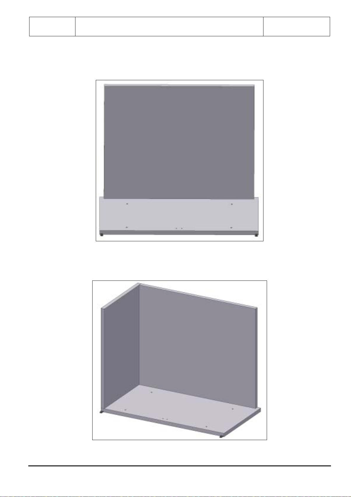
3.2 - Colocação
•Retirar com cuidado a embalagem para não danificar as superfícies do equipamento. Remover a película de plástico de
protecção.
•Aconselha-se a instalação do aparelho afastado de possíveis fontes de calor (como fornos, radiadores, etc.) e de luz solar
directa.
•Para assegurar um bom funcionamento, o aparelho deve ser sempre nivelado e colocado ligeiramente inclinado para trás, permitindo que
as portas fechem perfeitamente. As pequenas diferenças de nível podem ser compensadas através da regulação dos pés.
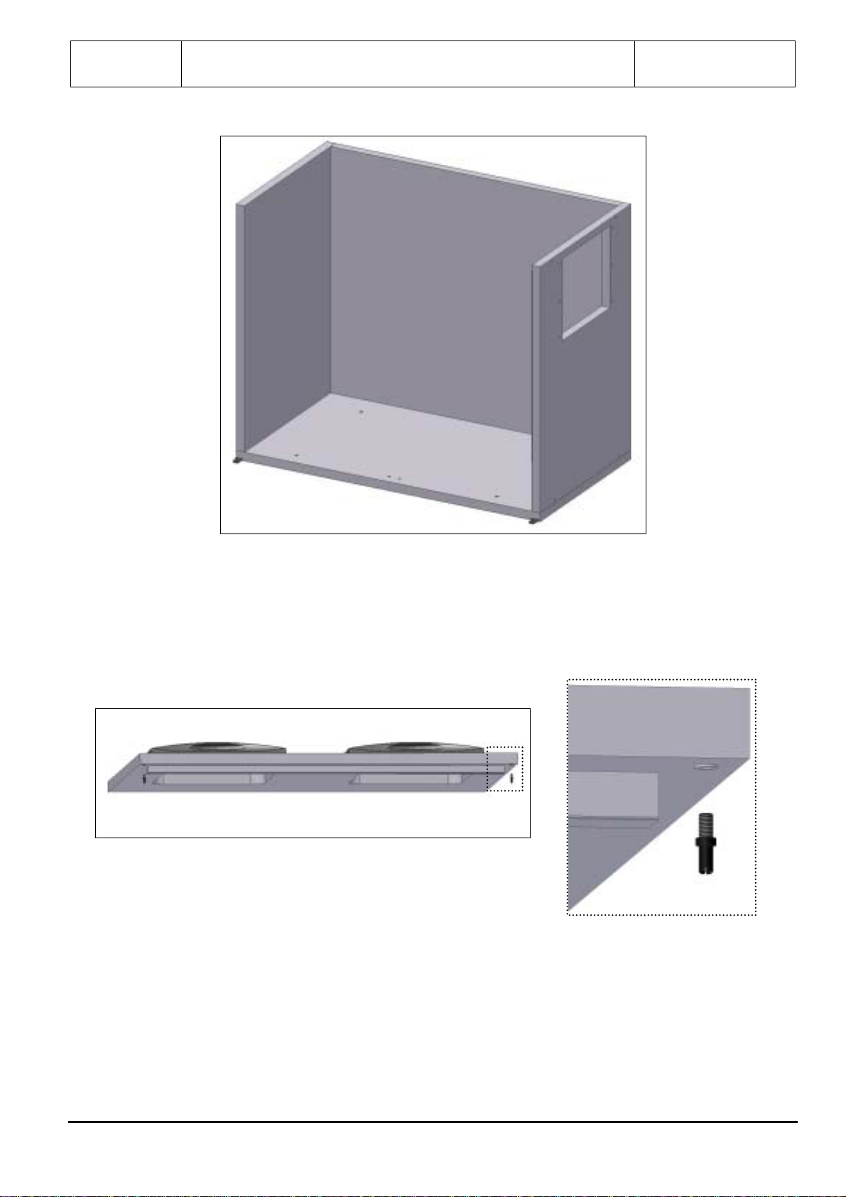
3.3 - Instalação
A instalação deve ser efectuada atendendo sempre às seguintes normas:
•Regulamentos referentes à construção de edifícios e normas contra incêndios.
•Regras em vigor quanto à prevenção de acidentes.
•Normas Europeias em vigor.
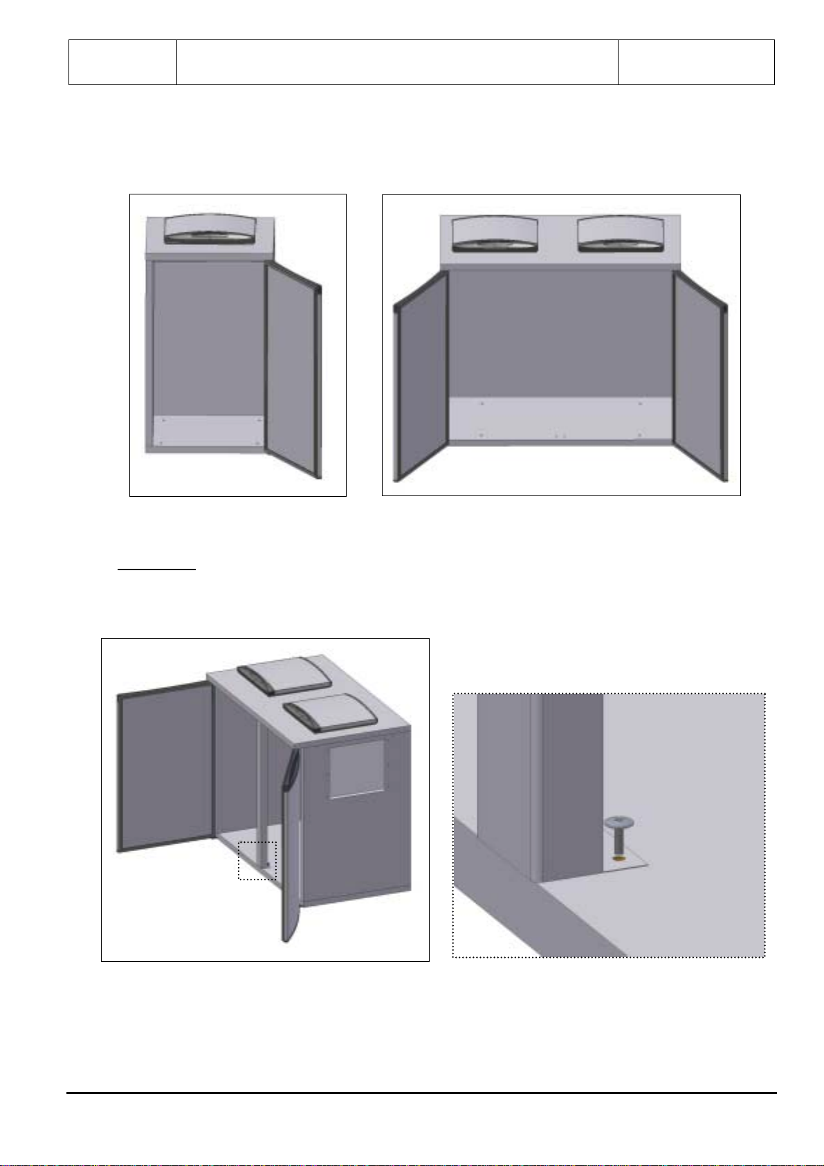
4 - Recomendações ao Utilizador
As câmaras refrigeradas foram concebidas para o arrefecimento de detritos.
Para assegurar um bom funcionamento é necessário observar as seguintes indicações:
•Evitar tanto quanto possível a abertura de portas.
•Ao introduzir os detritos, assegurar no interior uma boa circulação natural do ar.
•Não devem ser utilizados objectos aguçados (tais como facas, chaves de fendas, etc.) para remover gelo.
•Se os conselhos acima descritos não forem seguidos, haverá um aumento do consumo de energia.
4.1 - Limpeza
Para assegurar uma perfeita higiene e conservação, aconselha-se que efectue a seguinte limpeza:
•Limpar cuidadosamente as superfícies, usando um pano húmido.
•Utilizar água e um detergente neutro, não utilizar os que são à base de cloro ou abrasivos.

Manual de Montagem N.º MANUAL
INST V5
MANUAL INST V5 5/62
TEC
•Enxaguar com água pura e secar cuidadosamente.
•É absolutamente desaconselhável a utilização de jactos de água sob pressão.
5 – Montagem
Em cada painel existe um autocolante, onde o sombreado identifica o mesmo.A seta existente nos autocolantes dos painéis verticais aponta
para cima.
Proceder à montagem da câmara da seguinte forma:
!Colocar pernos inferiores na patilha de fixação da porta (Fig.1);
!Colocar painel do fundo sobre o piso e nivela-lo (Fig.2);
Fig. 1
1L
2L
Fig. 2

Manual de Montagem N.º MANUAL
INST V5
MANUAL INST V5 6/62
TEC
!Encaixar painel da costa sobre o painel do fundo e apertar (Fig.3);
!Encaixar painel lateral esquerdo sobre o painel do fundo e apertar apenas ao fundo (Fig.4);
!Encaixar painel lateral direito sobre o painel do fundo e apertar apenas ao fundo (Fig.5);
Fig. 3
Fig. 4

Manual de Montagem N.º MANUAL
INST V5
MANUAL INST V5 7/62
TEC
!Colocar pernos superiores no tampo (Fig. 6);
Fig. 5
Fig. 6

Manual de Montagem N.º MANUAL
INST V5
MANUAL INST V5 8/62
TEC
!Encaixar painel do tampo sobre os painéis laterais e painel da costa e apertar apenas à costa (Fig.7);
!Colocar casquilho na parte inferior da porta (fig. 8); Fig. 7
Fig. 8

Manual de Montagem N.º MANUAL
INST V5
MANUAL INST V5 9/62
TEC
!Encaixar porta no fundo e no tampo (Fig.9);
Apenas para 2L
!Fixar o pilar ao painel do tampo e fundo (Fig.10);
!Apertar restantes ganchos dos laterais e costas;
Fig, 9
1L 2L
Fi
g
. 10

Manual de Montagem N.º MANUAL
INST V5
MANUAL INST V5 10/62
TEC
Para o aperto dos ganchos, estando a trabalhar pelo lado de fora da câmara, deve proceder da seguinte forma:
!Rodar a chave no sentido dos ponteiros do relógio até parar (Fig.11 – Posição A);
!Rodar a no sentido contrário até apertar. (Fig.11 – Posição B)
!Após o aperto, colocar tacos nos furos (Fig. 11).
!Nivelar a câmara, através do ajuste dos pés.
!Colocar tacos no fundo (Fig. 12);
Fig. 11
A
B
Fig.

Manual de Montagem N.º MANUAL
INST V5
MANUAL INST V5 11/62
TEC
!Colocar pernos no rasgo do painel lateral direito (Fig. 13);
!Colocar V6 no rasgo do painel lateral direito, encaixando-o nos pernos (Fig. 14);
Fig.
Fig.

Manual de Montagem N.º MANUAL
INST V5
MANUAL INST V5 12/62
TEC
!Apertar V6 com 2 parafusos, pelo interior do painel lateral direito (Fig. 15);
!Após o aperto, colocar tacos nos furos (Fig. 16);
Fig.
Fig. 16

Assembly Instructions N.º MANUAL
INST V5
MANUAL INST V5 13/62
TEC
INDEX: Page
1. Reception 14
2. Identification 14
3. Recommendations for Installation 14
3.1 General notes 14
3.2 Placement 14
3.3 Installation 14
4. Recommendations to the User 14
4.1 Cleaning 15
5. Assembly 15
Notes:
We would like to thank your preference for our equipment, which follows all the European Directives and Standards and will
meet for sure, your expectations and satisfy your needs.
Thank you.

Assembly Instructions N.º MANUAL
INST V5
MANUAL INST V5 14/62
TEC
1. Reception:
On receiving the equipment, check carefully that the packaging is intact and has not been damaged in transit.
After unpacking, check that you have all the components and if the characteristics correspond to those on the order form.
Installation, maintenance and other work should be carried out by specialised and authorised technicians. The manufacturer accepts
no responsibility and will not cover the guarantee if these conditions are not respected.
This appliance must be used according to these instructions and only for the manufacturer’s purpose. The incorrect use of the equipment can
cause damages to the equipment and to users.
As a result of our constant effort to make technological improvements, the specifications indicated here are subject to change without warning.
2 – Identification:
Our models have a plate behind the control panel on which the main data can be found. The MODEL and SERIES / YEAR are absolutely
essential when consulting the manufacturer.
MODELO N.º SÉRIE/ANO
CÓDIGO MADEIN PORTUGAL
1
2
3
Legend:
1 - Model 3 - Series Number
2 - Code
3 – Recommendations for Installation:
3.1 – General Notes:
Although the production of each appliance is rigorously controlled during manufacture, this does not exclude the possibility of damage caused in
transit. The general condition of the appliance should therefore be checked on arrival.
3.2 - Placing:
•Remove the packaging or pallet carefully so that the equipment’s surfaces are not damaged. Remove the PVC protection.
•The appliance should be installed away from heat sources (ex: heating appliances) and direct sunlight.
•To ensure that the appliance functions well, it should always be correctly levelled and slightly inclined to the back, to make sure
that the doors close perfectly. Small differences in level can be compensated for by regulating the feet.
3.3 - Installation
The following standards should always be bared in mind during installation:
•Regulations concerning the buildings, and anti-fire standards.
•Rules concerning accident prevention.
•European standards into effect.
4 - Recommendations for the User
The boxes have been designed for cooling waste. To ensure that they function well, the following points must be followed:
•Avoid opening the doors as much as possible.
•When putting in the waste, make sure that there is good natural circulation of air inside.
•Do not use pointed objects to remove
•If you do not follow the advises above, there will be an increase usage of electrical energy.
4.1 - Cleaning:
To ensure perfect hygiene and conservation, clean as follows:
•Cleaning the surfaces frequently and carefully with a damp cloth.
•Always when using water and detergent, make sure these are neutral, and avoiding those which are chlorine-based or abrasive.

Assembly Instructions N.º MANUAL
INST V5
MANUAL INST V5 15/62
TEC
•Rinsing with clean water and drying carefully.
•It is entirely inadvisable to use pressurised jets of water, specially in the direction of the compressor.
5 – Assembly
There is a label on each panel, the darkest side identifies the panel. The dart on vertical panels points to the top.
Proceed to the assembly of the keg box as follows:
!Insert the inferior stud-pins in the fixing support of the door (Fig.1);
!Put the panel of the bottom on the floor and level it (Fig.2);
Fig. 1
1L
2L
Fig. 2

Assembly Instructions N.º MANUAL
INST V5
MANUAL INST V5 16/62
TEC
!Fix the back panel to the panel of the bottom and fasten (Fig.3);
!Fix the left-side panel to the panel of the bottom and fasten only the bottom (Fig.4);
!Fix the right-side panel to the panel of the bottom and fasten only the bottom (Fig.5);
Fig. 3
Fig. 4

Assembly Instructions N.º MANUAL
INST V5
MANUAL INST V5 17/62
TEC
!Insert the superior stud-pins in the top (Fig. 6);
Fig. 5
Fig. 6

Assembly Instructions N.º MANUAL
INST V5
MANUAL INST V5 18/62
TEC
!Fix the panel of the top to side and back panels, fasten only the back (Fig.7);
!Insert the sleeve in the inferior side of the door (fig. 8);
!Fix the door (right and left) to the bottom and to the top (Fig.9);
Fig. 7
Fig. 8

Assembly Instructions N.º MANUAL
INST V5
MANUAL INST V5 19/62
TEC
Only for 2 containers
!Fix the pillar to the panel of the top and bottom (Fig.10);
!Fasten the other camlocks of side and back panels;
To fasten the camlocks, being ouside the box, proceed as follows:
!Turn the screwdriver like the hands of a clock till it stops. (Fig.11 – Position A);
!Turn the screwdriver on the other sense till it fastens. (Fig.11 – Position B)
Fig, 9
1L 2L
Fi
g
. 10

Assembly Instructions N.º MANUAL
INST V5
MANUAL INST V5 20/62
TEC
!After fastening, insert the screw caps in the holes (Fig. 11).
!Level the box through the adjustment of feet.
!Insert the screw caps in the bottom (Fig. 12);
Fig. 11
A
B
Fig.
Table of contents
Languages:
Other Nordcap Accessories manuals
Popular Accessories manuals by other brands

Cardinal
Cardinal 200 Installation and technical manual

Echo
Echo SRM-280 installation instructions

Siemens
Siemens SITRANS WS100 instruction manual

National Instruments
National Instruments UMI-7764 user guide

Oaxis
Oaxis myFirst 3dPen user manual

LORENZ MESSTECHNIK
LORENZ MESSTECHNIK DR-2800 Operation manual