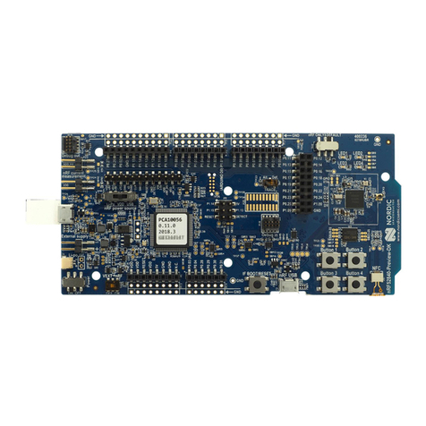
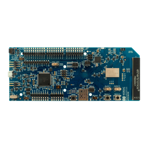
Nordic nRF5340 User manual

nRF5340 PDK
User Guide
v1.0
4406_489 v1.0 / 2019-11-13

Contents
Revision history.................................. iv
1Introduction................................... 5
2Minimum requirements............................ 6
3Kit content.................................... 7
3.1 Hardware content ................................ 7
3.2 Downloadable content .............................. 7
3.3 Related documentation .............................. 7
4Interface MCU.................................. 9
4.1 IF Boot/Reset button ............................... 9
4.2 Virtual COM port ................................ 9
4.2.1 Dynamic HWFC handling ........................... 10
4.3 MSD ..................................... 10
5Hardware description............................. 12
5.1 Hardware drawings ............................... 12
5.2 Block diagram ................................. 12
5.3 Power supply ..................................13
5.3.1 5 V power sources ..............................14
5.3.2 VDD power sources ............................. 14
5.3.3 Interface MCU power ............................ 16
5.3.4 nRF5340 power source ............................ 17
5.3.5 nRF5340 direct supply ............................ 18
5.4 Operating modes ................................ 19
5.4.1 USB detect ................................. 19
5.4.2 nRF only mode ............................... 19
5.4.3 Signal switches ............................... 20
5.5 External memory ................................ 21
5.6 Connector interface ............................... 22
5.6.1 Mapping of analog pins ........................... 24
5.7 Buttons and LEDs ................................ 24
5.8 32.768 kHz crystal ................................25
5.9 Debug input and trace .............................. 26
5.10 Debug output ................................. 27
5.11 NFC antenna interface ............................. 28
5.12 Extra op-amp ................................. 29
5.13 Solder bridge configuration ........................... 29
6Measuring current............................... 32
6.1 Preparing the PDK board ............................. 32
6.2 Using an oscilloscope for current profile measurement ................ 33
6.3 Using an ampere-meter for current measurement .................. 34
7RF measurements............................... 36
4406_489 v1.0 ii
Revision history
Date Version Description
November 2019 1.0 First release
4406_489 v1.0 iv

1Introduction
The nRF5340 Preview Development Kit (PDK) includes hardware, firmware source code, documentation,
hardware schematics, and layout files.
The key features of the development kit are:
• Support for nRF5340 System on Chip (SoC) development
• Support for the following wireless protocols:
•Bluetooth® Low Energy
• NFC
• 802.15.4
• Thread
• Zigbee
• ANT™
• 2.4 GHz proprietary
• Arduino Rev3 compatibility
• 2.4 GHz and NFC antennas
• SWF RF connector for direct RF measurements
• User-programmable LEDs(4) and buttons(4)
• SEGGER J-Link OB programmer/debugger
• Pins for measuring power consumption
• 1.7-5.0 V power supply from USB, external Li-Po battery, or CR2032 coin cell battery
For access to firmware source code, hardware schematics, and layout files, see www.nordicsemi.com.
4406_489 v1.0 5

2Minimum requirements
Before you start, check that you have the required hardware and software.
Hardware requirements
• Personal computer (PC) or Mac
• Micro-USB 2.0 cable
Software requirements
• Operating system: Windows 7, Windows 8, Windows 10, MacOS, or Linux
• SEGGER J-Link Software
4406_489 v1.0 6

3Kit content
The nRF5340 PDK consists of hardware, access to software components, reference design files, and
documentation.
3.1 Hardware content
The nRF5340 PDK contains the development kit board PCA10095 and a Near Field Communication (NFC)
antenna.
Figure 1: nRF5340 PDK board (PCA10095) and NFC antenna
3.2 Downloadable content
The nRF5340 PDK downloadable content includes the hardware files.
Hardware files
Schematics, layout, bill of materials, and Gerber files for the nRF5340 PDK are included in a zip file.
•nRF5340 PDK Downloads
3.3 Related documentation
In addition to the information in this document, you may need to consult other documents.
Nordic documentation
•nRF5340 Objective Product Specification
•nRF5340 Compatibility Matrix
•nRF5340 Errata
4406_489 v1.0 7

4Interface MCU
The interface MCU on the nRF5340 PDK board runs SEGGER J-Link OB interface firmware and is used to
program and debug the firmware of the nRF5340 SoC.
Figure 2: Interface MCU
4.1 IF Boot/Reset button
The nRF5340 PDK board is equipped with an IF Boot/Reset button (SW5).
This button is connected to the interface MCU on the board and has two functions:
• Resetting the nRF5340 SoC.
• Entering bootloader mode of the interface MCU.
The button is also used to enter the bootloader mode of the interface MCU. To enter the bootloader
mode, keep the reset button pressed while powering up the board until LED5 starts to blink. You can
power up the board either by disconnecting and reconnecting the USB cable or by toggling the power
switch (SW8).
4.2 Virtual COM port
The onboard interface MCU features a UART interface through a virtual COM port.
The virtual COM port has the following features:
•Flexible baud rate setting up to 1 Mbps.1
• Dynamic Hardware Flow Control (HWFC) handling.
• Tri-stated UART lines when no terminal is connected.
The table below shows an overview of the UART connections on nRF5340 and the interface MCU.
1Baud rate 921 600 is not supported through the virtual COM port.
4406_489 v1.0 9

Interface MCU
GPIO nRF5340 nRF5340 UART
P0.19 RTS
P0.20 TXD
P0.21 CTS
P0.22 RXD
Table 1: Relationship of UART connections on nRF5340 and interface MCU
The UART signals are routed directly to the interface MCU. The UART pins connected to the interface MCU
are tri-stated when no terminal is connected to the virtual COM port on the computer.
Note: The terminal software used must send a Data Terminal Ready (DTR) signal to configure the
UART interface MCU pins.
The P0.19 (Request to Send (RTS)) and P0.21 (Clear to Send (CTS)) can be used freely when HWFC is
disabled on the SoC.
4.2.1 Dynamic HWFC handling
When the interface MCU receives a DTR signal from a terminal, it performs automatic HWFC detection.
Automatic HWFC detection is done by driving P0.21 (CTS) from the interface MCU and evaluating the state
of P0.19 (RTS) when the first data is sent or received. If the state of P0.19 (RTS) is high, HWFC is assumed
not to be used. If HWFC is not detected, both CTS and RTS can be used freely by the nRF application.
After a power-on reset of the interface MCU, all UART lines are tri-stated when no terminal is connected
to the virtual COM port. Due to the dynamic HWFC handling, if HWFC has been used and detected, P0.21
(CTS) will be driven by the interface MCU until a power-on reset has been performed or until a new DTR
signal is received and the detection is redone.
To ensure that the UART lines are not affected by the interface MCU, the solder bridges for these signals
can be cut and later resoldered if needed. This might be necessary if UART without HWFC is needed while
P0.19 (RTS) and P0.21 (CTS) are used for other purposes.
4.3 MSD
The interface MCU features an Mass Storage Device (MSD). This makes the development kit appear as an
external drive on your computer.
This drive can be used for drag-and-drop programming. However, files cannot be stored on this drive. By
copying a HEX file to the drive, the interface MCU will program the file to the device.
Note:
• Windows might try to defragment the MSD part of the interface MCU. If this happens, the
interface MCU will disconnect and be unresponsive. To return to normal operation, the
development kit must be power cycled.
• Your antivirus software might try to scan the MSD part of the interface MCU. Some antivirus
programs trigger a false positive alert in one of the files and quarantine the unit. If this happens,
the interface MCU will become unresponsive.
• If the computer is set up to boot from USB, it can try to boot from the development kit if the
development kit is connected during boot. This can be avoided by unplugging the development
kit before a computer restart, or changing the boot sequence of the computer.
4406_489 v1.0 10

5Hardware description
The nRF5340 PDK board PCA10095 can be used as a development platform for the nRF5340 SoC. It
features an onboard programming and debugging solution.
In addition to radio communication, the nRF5340 SoC can communicate with a computer through USB and
a virtual COM port provided by the interface MCU.
5.1 Hardware drawings
nRF5340 PDK hardware drawings show both sides of the PCA10095 board.
Figure 3: nRF5340 PDK board (PCA10095) front view
Figure 4: nRF5340 PDK board (PCA10095) back view
5.2 Block diagram
The nRF5340 PDK block diagram shows the connections between the different blocks.
4406_489 v1.0 12

Hardware description
GPIO
LEDs
Buttons
External
memory
Matching
network
Osc
16 MHz
Osc
32.768 kHz
Debug in
nRF5340
Analog switch
nRF only
mode switch
Current
measurement
nRF power
source switch
Li-ion
Interface
MCU
Analog switch
Power supply
circuitry
Power switch
IF MCU USB
Battery
External
supply
Debug out
IF Boot/Reset
RF connector
Antenna
Figure 5: Block diagram
5.3 Power supply
The nRF5340 PDK board PCA10095 has multiple power options.
The power options are:
• USB connector J2 for the interface MCU (5 V)
• Lithium polymer (Li-Po) battery connectors J6 or P27 (2.5–5.0 V)
• VIN 3–5 pin on P20 (3.0–5.0 V)
• External supply on P21 (1.7–3.6 V)
• Coin cell battery
Figure 6: Power supply options (board front)
4406_489 v1.0 13

Hardware description
Figure 7: Power supply options (board back)
5.3.1 5 V power sources
The nRF5340 PDK board has a 5 V boost regulator.
It gives a stable 5 V output from four possible sources:
• USB connector J2 for the interface MCU
• Li-Po polymer battery connectors (J6 or P27)
• VIN 3–5 V pin on P20
Each of these sources has a reverse protection diode to prevent current flowing in the wrong direction if
multiple sources are connected at the same time.
Figure 8: 5 V regulator and protecting diodes
5.3.2 VDD power sources
The main board supply (VDD) can be sourced from the 5 V domain, external power supply, and coin cell
battery.
For the 5 V domain, there are two regulators, one fixed 3 V buck regulator and one voltage follower
regulator that follows the VDD_nRF voltage. The coin cell battery and external power supply are not
regulated.
• 5 V domain:
• Fixed 3 V buck regulator
• VDD_nRF voltage follower
• External power supply
• Coin cell battery
For more information about power sources, see nRF5340 power source on page 17.
The power sources are routed through a set of load switches, which is controlled by logic to give the
correct priority of the power sources.
If the high voltage regulator of the nRF5340 is used, the board will be supplied from the VDD_nRF voltage
follower regardless of the state of the other power sources.
4406_489 v1.0 14

Hardware description
Figure 9: Power supply circuitry
4406_489 v1.0 15

Hardware description
The power switches work in the way that the body diode of the internal transistor powers the VSUPPLY
net, which supplies the gates controlling the enable signal of the switches. If 5 V is present, the switches
for external supply and battery are disabled. If external supply is present, the switch for the battery is
disabled.
The power switches can be bypassed by shorting one or more solder bridges.
Power source Power switch bypass Voltage level
Regulator SB34 3.0 V
Coin cell battery SB35 Battery
External supply SB36 1.7 V–3.6 V
Table 2: Power switch bypass solder bridges
Figure 10: Power switch bypass solder bridges
Note: Connect only one power source at a time. Shorting the solder bridges removes the reverse
voltage protection.
5.3.3 Interface MCU power
The power for the interface MCU is routed through two load switches, one for the VDD supply and one for
the USB supply. This makes it possible to disconnect the interface MCU from the power domain when not
in use.
4406_489 v1.0 16

Hardware description
Figure 11: Interface MCU power switch
These switches are controlled by the presence of a USB connected to the interface MCU USB connector
(J2), and the state of the nRF only switch (SW6). See section Operating modes on page 19 for more
information.
5.3.4 nRF5340 power source
The nRF5340 PDK board has a power source switch (SW9) for selecting between three power sources for
the nRF5340 SoC.
The three positions of the switch are:
• VDD (default)
• Li-Po
• USB
Figure 12: nRF5340 power source switch
4406_489 v1.0 17

Hardware description
The nRF5340 SoC has a high voltage buck regulator that can support up to 5 V input. In the VDD position,
the SoC is powered either from the on-board buck regulator, coin cell battery, or external supply (P21).
In the Li-Po position, the high voltage regulator of the SoC is supplied directly from the Li-Po battery
connectors (J6 or P27). In the USB position, the USB high voltage regulator gets power from the nRF5340
USB connector (J3).
When the high voltage regulator is used, the VDD_nRF voltage can be set by the firmware of the SoC. To
make sure the rest of the board has the same voltage level, the VDD of the board is sourced by a regulator
following the VDD_nRF voltage when the high voltage regulator is used.
Figure 13: VDD_nRF voltage follower and switch
To make sure that the nRF5340 is not powered when the nRF power switch (SW8) is OFF, two load
switches are used, one for the high voltage regulator (U15) and one for the USB supply (U20). These
switches are controlled by VDD.
5.3.5 nRF5340 direct supply
It is possible to power the SoC directly from a source without powering the rest of the board from the
same source.
The external source can be connected to the external supply connector (P21) and the VEXT->nRF switch
(SW10) put in the ON position. The nRF power source switch (SW9) must be in the VDD position, and the
allowed voltage range is 1.7–3.6 V.
Figure 14: VEXT->nRF switch (SW10)
4406_489 v1.0 18

Hardware description
Since it is only the nRF5340 SoC that is supplied from this source, it is recommended to supply the VDD
domain from a different source to prevent the pins of the SoC to be connected to unpowered devices.
To avoid voltage differences on the board, the External supply is also connected to the input of the voltage
follower when SW10 is in the ON position. The voltage follower circuit requires 5 V to be present on the
board, see section 5 V power sources on page 14.
The voltage follower can be disconnected from the External supply by cutting SB58. To prevent leakage
due to voltage differences, the board should be set in the nRF only mode, see section Operating modes on
page 19.
Note: To reduce trace length and parasitic components, the external memory is connected to the
SoC directly instead of using analog switches. It is recommended to cut solder bridges to avoid
leakage, see section External memory on page 21.
5.4 Operating modes
The nRF5340 PDK board has various modes of operation.
5.4.1 USB detect
To detect when USB for the interface MCU is connected, there is a circuit sensing the VBUS of USB
connector J2.
When the USB cable is connected, the VDD is propagated to the USB_DETECT signal.
Figure 15: USB detect
5.4.2 nRF only mode
The nRF only mode disconnects the power supply of the interface MCU, the external memory, and the
LEDs as well as disconnects the signal lines between the nRF5340 SoC and the interface MCU using analog
switches.
This is done to isolate the chip on the board as much as possible, and can be of use when measuring
currents on low-power applications.
The power supply of the external memory can be changed to maintain operation in the nRF only mode.
See section External memory on page 21.
4406_489 v1.0 19

Hardware description
Figure 16: nRF only switch (SW6)
5.4.3 Signal switches
On the nRF5340 PDK board, there are multiple analog switches that are used to connect and disconnect
signals based on different scenarios.
Figure 17: Signal switches
The USB and SW6 control the signal switches by using USB_DETECT as an input to SW6. Therefore, the
interface MCU can be disconnected either by unplugging the USB cable in J2 or by toggling SW6.
The signal controls a set of switches (U3, U5, U6) that break the connection between the nRF5340 and the
interface MCU, and control the power for the interface MCU. For more information, see section Interface
MCU power on page 16.
4406_489 v1.0 20
Table of contents
Other Nordic Microcontroller manuals

Nordic
Nordic 51822 Technical manual

Nordic
Nordic nRF51822 User manual

Nordic
Nordic PCA63511 User manual

Nordic
Nordic nRF9160 User manual

Nordic
Nordic nRF5 Series: nRF52 User manual

Nordic
Nordic nRF51822 User manual

Nordic
Nordic nRFgo nRF6700 User manual

Nordic
Nordic nRFgo nRF8002 User manual

Nordic
Nordic nRF8001 User manual