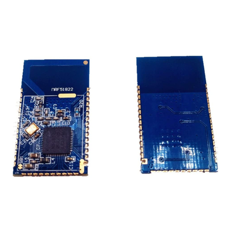
Nordic nRF51822 User manual

Copyright © 2012 Nordic Semiconductor ASA. All rights reserved.
Reproduction in whole or in part is prohibited without the prior written permission of the copyright holder.
nRF51822 Development Kit
nRF51822
User Guide v1.0

Page 2 of 59
nRF51822 Development Kit User Guide v1.0
Contents
1 Introduction............................................................................................................................................... 4
1.1 Minimum requirements................................................................................................................................. 4
1.2 External resources ............................................................................................................................................ 4
1.3 Writing conventions........................................................................................................................................ 4
1.4 Development kit release notes.................................................................................................................... 4
2 Quick start.................................................................................................................................................. 5
2.1 Bluetooth low energy heart rate monitor demo .................................................................................. 9
3 Kit content................................................................................................................................................ 11
3.1 nRF51822 Development kit hardware content...................................................................................11
3.2 Downloadable content ................................................................................................................................12
3.2.1 nRF51822 DK software content..........................................................................................................12
3.2.2 nRF51822 DK documentation.............................................................................................................12
3.2.3 Schematics, Bill of Materials, PCB layout files, and production files......................................12
4 Development kit configuration ........................................................................................................... 13
4.1 Development environment........................................................................................................................13
4.1.1 Programming the nRF51822 device .................................................................................................13
4.2 Kit set up ............................................................................................................................................................16
4.2.1 nRFgo nRF51822 DK modules.............................................................................................................16
4.2.2 nRF51822 development dongle (PCA10000) ................................................................................17
4.2.3 J-Link Lite CortexM-9 JTAG/SWD Emulator....................................................................................17
5 Hardware description ............................................................................................................................ 18
5.1 nRFgo nRF51822 DK modules ...................................................................................................................18
5.1.1 Key features................................................................................................................................................18
5.1.2 Hardware pictures ...................................................................................................................................18
5.1.3 Block diagram ...........................................................................................................................................20
5.1.4 nRFgo nRF51822 DK module extension..........................................................................................21
5.1.5 Analog Inputs............................................................................................................................................22
5.1.6 SWD interface............................................................................................................................................22
5.1.7 32.768 kHz crystal ....................................................................................................................................23
5.1.8 Current measurements..........................................................................................................................24
5.2 nRF51822 development dongle(PCA10000)........................................................................................25
5.2.1 Key features................................................................................................................................................25
5.2.2 Hardware pictures ...................................................................................................................................25
5.2.3 Block diagram ...........................................................................................................................................26
6 Flash programming and application development......................................................................... 27
6.1 Programming and erasing flash using nRFgo Studio .......................................................................27
6.1.1 Selecting a board to program .............................................................................................................27
6.1.2 Identifying the nRF51 chip and chip content................................................................................27
6.1.3 Erasing All ...................................................................................................................................................29
6.1.4 Programming a SoftDevice ..................................................................................................................30
6.1.5 Programming an application ..............................................................................................................31
6.2 Application development ...........................................................................................................................32
6.2.1 Configuring memory layout ................................................................................................................32
6.2.2 Shared call stack.......................................................................................................................................35
6.2.3 Debugger configuration .......................................................................................................................36
6.2.4 Limitation when debugging on a chip with a SoftDevice ........................................................38
Page 3 of 59
nRF51822 Development Kit User Guide v1.0
6.2.5 Programming the device ......................................................................................................................38
6.2.6 Erasing the device....................................................................................................................................40
7 Debugging the nRF51822..................................................................................................................... 41
7.1 nRF51 debug features and precautions.................................................................................................41
7.1.1 System Viewer Windows.......................................................................................................................41
7.1.2 Debugging an application when a read back protected SoftDevice is present ...............43
7.1.3 Setting a breakpoint using SEGGER J-Link debugger ................................................................45
8 Testing the physical layer with Direct Test Mode ............................................................................ 46
8.1 Kit setup for UART ..........................................................................................................................................46
8.2 Programming the nRF51822 module .....................................................................................................48
8.3 DTM testing using nRFgo Studio..............................................................................................................49
9 Software Development Kit ................................................................................................................... 50
9.1 Installing the nRF518 SDK ...........................................................................................................................50
10 Troubleshooting ..................................................................................................................................... 51
Appendix A: Installing drivers and configuring KEIL projects for the SEGGER debugger ....................53

Page 4 of 59
nRF51822 Development Kit User Guide v1.0
1 Introduction
The nRF51822 Bluetooth® low energy/2.4 GHz Proprietary Development Kit (DK) provides a complete
solution for development, testing, and evaluating the nRF51822 device. The nRF51822 is part of the nRF51
series which offers a range of ultra-low power, System on Chip (SoC) solutions for your 2.4 GHz wireless
products.
1.1 Minimum requirements
•nRFgoStarterKit
• nRFgo Studio v1.13 or later
• Computer with a minimum of 2 USB ports; 4 are preferable
• Windows XP or Windows 7
1.2 External resources
• Keil MDK-ARM Lite v4.54 or later https://www.keil.com/demo/eval/arm.htm
• J-Link Software v4.52b or later
1.3 Writing conventions
This User Guide follows a set of typographic rules that makes the document consistent and easy to read. The
following writing conventions are used:
• Commands are written in Lucida Console.
• Pin names are written in Consolas.
• File names and User Interface components are written in bold.
• Internal cross references are italicized and written in semi-bold.
1.4 Development kit release notes
Date Version Description
September
2012
1.0 Known issues
• PCA10000, PCA10004 and, PCA10005 v1.0:
• The antenna matching network and layout on these boards is suitable
for applications using TX output power 0 dBm or less. These boards are
not suitable for applications using +4 dBm TX output power.

Page 5 of 59
nRF51822 Development Kit User Guide v1.0
2 Quick start
Register, download, and install
1. Download and install Keil MDK-ARM Lite from https://www.keil.com/demo/eval/arm.htm to your
hard drive. If you have Keil MDK-ARM Lite version 4.54 or later already installed, go to step 2.
2. Download and run the J-Link Software (version 4.52b or later) and documentation pack for
Windows from http://www.segger.com/jlink-software.html. The serial number from your SEGGER
J-Link hardware is needed.
3. During installation you will be prompted to select the IDE that should be updated with the latest
SEGGER DLLs. Check the box for Keil MDK and any other IDEs you want to use with SEGGER.
4. Go to http://www.segger.com/IDE_Integration_Keil.html#knownproblems for MDK v4.54.
Download JL2CM3 and copy it to <keil>/ARM/Segger. This patch is necessary for the SEGGER
debugger to work.
5. Go to www.nordicsemi.com and log in to your Nordic My Page account.
6. Select My Products from the left menu.
7. Enter the product key (included with this kit) into the Product Key field and click Add.
8. Click the Downloads link in the Overview, My Products table.
9. Download and run the nRF518 SDK installer. Make sure to choose the Keil MDK-ARM installer
option.

Page 6 of 59
nRF51822 Development Kit User Guide v1.0
Connect the hardware
1. Screw the antenna into the SMA connector on the nRF51822 DK SMA connector module.
2. Ensure that header K3 has a jumper connecting pin 2 and 3. The two upper rows of P4 should
have two jumpers placed vertical matching the 32 kHz marking.
3. Plug the nRF51822 DK SMA connector module into the nRFgo Starter Kit Motherboard (nRF6310).
4. Connect a USB cable from the Motherboard to your computer.
5. Using two 10 pin flat cables (2.54 mm, included in the nRFgo Starter Kit), connect one cable
between P8 (PORT0) and P1 (BUTTONS) and one between P10 (PORT1) and P2 (LEDS) on the
nRFGo Motherboard. Make sure the red marking on the cable is always connected to pin 1, as
shown below.
6. Connect the SEGGER J-Link board to the nRF51822 module with the 10 pin flat cable (1.27 mm,
provided in the Development Kit).
7. Connect a USB cable from the J-Link board to your computer.
Turn on and set the supply voltage
1. Turn the S8 switch on the Motherboard to VBUS.
2. Turn the On/Off switch on the Motherboard to ON.
SMA connector K3 header
P8
P1P10
P2

Page 7 of 59
nRF51822 Development Kit User Guide v1.0
3. The VCC and VTG LEDs will light up..
4. Start nRFgo Studio. The Motherboard firmware may require an update, and if needed, you will be
prompted to begin the update. If this occurs, click OK and wait for the update to complete.
Note: While updating the firmware, the screen will look similar to the image on the left below.On
completion of the update, the “Updating…” message will change to “Upgrade” as seen in the
figure on the right; however, this option is not immediately available after the latest update
and will be greyed out.
S8 switch
On/Off switch
VCC and VTG LED
Board ID

Page 8 of 59
nRF51822 Development Kit User Guide v1.0
5. Select the desired Motherboard from the Device Manager pane in nRFgo Studio. To find the board
ID, look on the 7-segment display on the Motherboard.
6. In nRFgo Studio, you can control the supply voltage (VTG) to the connected nRF51822 module.
Make sure the voltage is set to 3.3 V.
Note: Please refer to nRFgo Studio's help file for further information. To access, while in nRFgo
Studio, press F1 and the help file opens.
Note: The nRF51822 device is capable of operating at higher and lower voltages. This can be tested
when the debugger is not required for programming or debugging the application. However,
for the J-Link Lite Cortex-M (that is included in the kit) to function correctly, the supply voltage
must be set to 3.3 V on the Motherboard. At all voltages other than 3.3 V, the J-Link Lite
CortexM-9 debugger should be disconnected from the nRF51822 module (SEGGER has
debuggers that are capable of debugging in the entire voltage range). The supply voltage
operating range of the nRF51822 device is stated in the Product Specification.
Start the Blinky project
1. Locate the Blinky project found under <keil path>
\ARM\Device\Nordic\nRF51822\Board\nrf6310\blinky_example\arm.
2. Open the Blinky project in Keil Vision by double clicking the blinky.uvproj file.
3. From the Select Target list, select “nRF51822” and then click Build or press F7 to compile the
Blinky project.
4. Click Load to download and run the Blinky example firmware. LED0 to LED7 on the nRFgo Starter
Kit Motherboard should now blink in a sequential order.

Page 9 of 59
nRF51822 Development Kit User Guide v1.0
2.1 Bluetooth low energy heart rate monitor demo
Download and program the SoftDevice
Access the S110 nRF51822 SoftDevice by entering the product key (included with the Development Kit) into
the Product Key field in My Page.
To program your device:
1. Open nRFgo Studio.
2. Open the Device Manager. Select the motherboard your module is connected to.
3. Select the module.
4. If you have more than one SEGGER debugger connected, you need to select which one you want
to use.
5. Select the Program SoftDevice tab.
6. Click Browse and navigate to the file you downloaded.
7. Click Program.

Page 10 of 59
nRF51822 Development Kit User Guide v1.0
Compile, program, and run the heart rate monitor demo
1. Locate the Heart Rate demo project found in the folder <keil path>
\ARM\Device\Nordic\nrf51822\board\nrf6310\ble\ble_app_hrs\arm.
2. Open the Heart Rate demo project in Keil Vision by double clicking the ble_app_hrs.uvproj file.
3. Click the Build icon or press F7 to build the project.
4. Only one SEGGER device should be connected to your computer. Make sure it is also connected to
the nRF51822 development module to ensure the program is downloaded to the correct target.
5. Go to the Flash menu and click Download to load the program (or click the Load icon).
6. The Heart Rate demo example will start executing. LED0 should be lit indicating it is advertising.
7. The application advertises for 3 minutes. If a connection isn’t made within this period, the
application sets nRF51822 in System Off.
8. To start advertising again press Button 0 (or the nRF Reset button)
Install the nRF51822 development dongle (PCA10000)
1. Plug the nRF51822 development dongle into a USB port on your computer.
2. An icon will appear in the lower right corner of your monitor showing that the drivers are being
installed. Wait until it is ready.
Note: The development dongle must be unplugged when loading example programs into the flash.
Scan for available Bluetooth low energy devices
1. Start the Master Control Panel from the Windows Start menu (Start > All Programs > Nordic
Semiconductor > Master Control Panel).
2. Make sure the Master Emulator is detected. The Master Emulator item list should show
COMnn-xxxxxxxxx (nn gives the COM port number; xxxxxxxxx is the SEGGER serial number printed
on the dongle). Restart the application if it doesn’t appear in the item list. Before continuing, make
sure you have selected the correct device by verifying the serial number in the item list with the
serial number printed on the device.
3. When you use the nRF51822 development dongle for the first time, you must first program it with
the Master Emulator Firmware.
a. In the Master Control Panel menu click File and select Flash Programming.
b. Click Browse. This opens a browser that automatically points to the location of the
mefw_nrf51822_<version>_firmware.hex (<version> will be replaced by a number
giving the version of the actual firmware).
c. Select the Master Emulator Firmware file and click Open.
d. Click Program to start programming the selected device.
e. When the programming is finished click Exit to go back to the main window.
4. Click Start discovery. The Master Emulator will scan for available Bluetooth low energy devices
within range and list them.
5. Select the device that appears in the Discovered Devices list. (The device will identify itself with
CompleteLocalName equal to HRS_APPVx.x)
6. Select the device and click Select device.
7. Click Service Discovery. In the Service discovery pane you will see the services and
characteristics of the device. On the Motherboard LED0 will go off and LED1 will light up
indicating that is has gone from advertising to connected.
8. Click Enable services. You should see the Heart Rate Measurement characteristic and Battery Level
being notified every few seconds with a different value (the Heart Rate Measurement/Battery
Level value line will blink green for each notification).

Page 11 of 59
nRF51822 Development Kit User Guide v1.0
3 Kit content
The nRF51822 Development Kit (DK) consists of hardware and access to software components,
documentation, and design files from www.nordicsemi.com.
3.1 nRF51822 Development kit hardware content
Figure 1 nRF51822 DK hardware content
1 x nRF51822 DK
PCB antenna module
(PCA10004)
1 x nRF51822 DK
SMA connector module
(PCA10005)
1 x nRF51822
development dongle
(PCA10000)
2 x J-Link Lite CortexM-9
JTAG/SWD Emulators
1 x Helical monopole SMA antenna
2 x USB cables
5 x nRF51822 chip samples
1 x 10 pin connector

Page 12 of 59
nRF51822 Development Kit User Guide v1.0
3.2 Downloadable content
The nRF51822 Development Kit includes firmware source code, documentation, hardware schematics, and
layout files. To access this information, log in to your My Page account, enter your product key, and
download the files.
3.2.1 nRF51822 DK software content
•nRFgoStudio
• nRF518 Software Development Kit (SDK)
• Precompiled HEX files
•Sourcecode
• Keil ARM project files
• S110 nRF51822 SoftDevice
3.2.2 nRF51822 DK documentation
•ThisUserGuide
• nRF51 Series Reference Manual
• nRF51822 PPS
• S110 SoftDevice Specification
• nRF518 SDK
• nRF51822 PAN
3.2.3 Schematics, Bill of Materials, PCB layout files, and production files
The ZIP file and its subdirectories contain the hardware design files for the nRF51822 DK.
• Altium Designer files
• PCB layout files
• Production files
•Assemblydrawings
• Drill files
•Gerberfiles
•PickandPlacefiles
• Bill of Materials
•Schematics

Page 13 of 59
nRF51822 Development Kit User Guide v1.0
4 Development kit configuration
This chapter explains how to download third party content, the development environment setup, and how
to program the nRF51822.
4.1 Development environment
ARM compiler/IDE (not included in this kit)
All the source code projects and examples can be compiled and used with the Keil Microcontroller
Development Kit (MDK). For full use of the Development Kit source code projects, and to upgrade firmware,
download and install the free KEIL MDK-ARM Lite from https://www.keil.com/demo/eval/arm.htm.
J-Link Lite CortexM-9 driver (not included in this kit)
For installing drivers for the SEGGER J-Link Lite CortexM-9, visit www.segger.com and go to the Downloads
section. Select the J-Link Lite and download the software and documentation. You must correctly install the
drivers for the device to use the J-Link debugger with Keil MDK. See Appendix A: “Installing drivers and
configuring KEIL projects for the SEGGER debugger” on page 53.
4.1.1 Programming the nRF51822 device
The nRF51822 device can be programmed from several environments. In this section we will show how to
program using Keil MDK-ARM. The nRF51822 DK can be configured to develop proprietary 2.4 GHz protocol-
based applications and Bluetooth 4.0 single-mode applications.
For development of proprietary 2.4 GHz protocol-based applications, you need:
• 2 x Motherboards (from the nRFgo Starter Kit - not included)
• 2 x nRF51822 modules
For development or demonstration of Bluetooth 4.0 single-mode applications, you need:
• 1 x Motherboard with attached nRF51822 module
• 1 x nRF51822 development dongle (PCA10000)
• Master Control Panel PC software
Figure 2 and Figure 3 show the relationship between the hardware and software components, and the
Motherboard(s).
Note: The Keil µVision IDE is not included in the kit content.

Page 14 of 59
nRF51822 Development Kit User Guide v1.0
Figure 2 nRF51822 DK configuration for 2.4 GHz based development
USB
USB
10 pin Flat
Cable
J-Link Lite
USB
USB
Keil µVision IDE
J-Link Lite
Application
Programming &
Erase (Via J-Link)
Examples and Applications
written for Keil / IAR / GCC
Configure
Voltage
nRFgo Studio
nRFgo Starter Kit
10 pin Flat
Cable
SAMSUNG
nRF51822
module
nRF51822 DK
nRF518 SDK

Page 15 of 59
nRF51822 Development Kit User Guide v1.0
Figure 3 nRF51822 DK configuration for Bluetooth 4.0 single-mode
USB
USB
Keil µVision IDE
J-Link Lite
Application
Programming &
Erase (Via J-Link)
Examples and Applications
written for Keil / IAR / GCC
Configure
Voltage
nRFgo Studio
nRFgo Starter Kit
10 pin Flat
Cable
USB
nRF51822
module
SAMSUNG
Control
nRF51822 DK
Master Control Panel
nRF518 SDK
PCA10000

Page 16 of 59
nRF51822 Development Kit User Guide v1.0
4.2 Kit set up
Figure 4 Kit set up
4.2.1 nRFgo nRF51822 DK modules
The nRF51822 modules contain the nRF51822 device and its interfaces (see section 5.1 on page 18 for a
complete description). The modules are plugged into, and powered from, the Motherboard. Make sure the
jumper on header K1 is placed in the default position as described in section 5.1.8 on page 24. The
Motherboard is connected to your computer with a USB cable and turned on as described"Turn on and set
the supply voltage" on page 6.
Note: On the Motherboard, the two 10 pin flat cables connecting P8 (PORT0) and P1 (BUTTONS), and
P10 (PORT1) and P2 (LEDS) are required to connect the correct I/Os to the LEDs for the
example projects in "Quick start" on page 5and for projects in the SDK.
Note: With the nRFgo Studio application you can control the supply voltage (VTG) to the connected
nRF51822 development dongle as described in "Turn on and set the supply voltage" on
page 6.
P8 P1P10
P2
nRF51 module
USB connected to computer
J-Link Lite
CortexM 10 pin 2.54 mm
flat cable
10 pin 1.27 mm
flat cable

Page 17 of 59
nRF51822 Development Kit User Guide v1.0
4.2.2 nRF51822 development dongle (PCA10000)
The nRF51822 development dongle (PCA10000) enables you to see the data sent between the dongle and a
single nRF51822 device. The nRF51822 development dongle is plugged into a USB port on your computer
as described in "Compile, program, and run the heart rate monitor demo" on page 10.
4.2.3 J-Link Lite CortexM-9 JTAG/SWD Emulator
The programming and debugging (SWD) interface of the nRF51822 device is accessed through a 10 pin
connector (P3) on the nRF51822 DK module.
Figure 5 Pin 1 position on the SEGGER J-Link Lite CortexM-9
Connect the JTAG/SWD emulator using the 10 pin 1.27 mm flat cable supplied with the kit to the nRF51822
DK module at P3 and to your computer with a USB cable, as shown in Figure 6.
Figure 6 nRF51822 DK module connected to the SEGGER J-Link Lite CortexM-9
Pin 1

Page 18 of 59
nRF51822 Development Kit User Guide v1.0
5 Hardware description
This chapter describes the nRF51822 DK modules and the nRF51822 development dongle (PCA10000).
5.1 nRFgo nRF51822 DK modules
The nRF51822 modules (PCA10004, PCA10005) are delivered with an unprogrammed nRF51822 chip.
5.1.1 Key features
The nRF51822 DK modules have the following key features:
• 2.4 GHz compatible with nRF24L devices
•Bluetooth low energy compatible
• nRF51822 IC
• Current Shunt Monitor (CSM) for current measurements
• nRFgo Motherboard integration
• PCB antenna (PCA10004 only)
• SMA connector compatibility (PCA10005 only)
• SWD interface connector for programming and debugging
5.1.2 Hardware pictures
Figure 7 nRF51822 DK module (PCA10004) top

Page 19 of 59
nRF51822 Development Kit User Guide v1.0
Figure 8 nRF51822 DK module (PCA10004) bottom
Figure 9 nRF51822 DK module (PCA10005) top

Page 20 of 59
nRF51822 Development Kit User Guide v1.0
Figure 10 nRF51822 DK module (PCA10005) bottom
5.1.3 Block diagram
Figure 11 nRF51822 DK module block diagram
Ext A1 Ext B1
Analog nRF51822 6x6 Matching
network
SMA/
PCB
antenna
CSM
Cortex
Debug
Osc
16 MHz
Osc
32.768 kHz
RESET
Other manuals for nRF51822
2
Table of contents
Other Nordic Microcontroller manuals

Nordic
Nordic 51822 Technical manual

Nordic
Nordic nRF5340 User manual

Nordic
Nordic nRF51822 User manual

Nordic
Nordic nRF5 Series: nRF52 User manual

Nordic
Nordic nRF9160 User manual

Nordic
Nordic nRF8001 User manual

Nordic
Nordic PCA63511 User manual

Nordic
Nordic nRFgo nRF6700 User manual

Nordic
Nordic nRFgo nRF8002 User manual