manuals.online logo
Brands
  1. Home
  2. •
  3. Brands
  4. •
  5. Norgren
  6. •
  7. Control Unit
  8. •
  9. Norgren 82 Series User manual

Norgren 82 Series User manual

CN –
欲了解更多信息和其他 言版本
:
DE – Für weiterührende Informationen diesen QR-Code scannen oder siehe:
ES – Para más información y otros idiomas, escanear este código QR o visitar:
FR – Pour plus d’informations et d’autres langues, consultez ce code QR ou visitez:
IT – Per ulteriori informazioni e altre lingue scansionare questo QR code o visitare:
PT – Para mais informação e outros idiomas scanea este código QR ou visite a:
RU – Для получения более подробной информации, в том числе на других языках,
пожалуйста, отсканируйте QR код или посетите :
https://www.norgren.com/excelon-plus
For further information and other languages scan this QR code or visit:
08/20
Excelon®Plus 3/2 VALVES
Air Preparation Range
1/4”, 3/8” 82 Series
3/8”, 1/2”, 3/4” 84 Series
Installation and Maintenance Instructions
Fluid: Compressed air
Maximum supply pressure: 10 bar (145 psig)
Operating temperature*: -20 °C to +65 °C (-4 °F to +149 °F)
*Air supply must be dry enough to
avoid ice formation at temperatures
below +2 °C (+35 °F)
Typical low @ P1=6.3 bar
(90 psi) & 0.5 bar (7.25 psi)
pressure drop:
82 Series: 20.7 dm/s (44 scfm)
84 Series: 50 dm/s (106 scfm)
Typical exhaust low @ P1
= 6.3 bar (90 psi) & 0.5 bar
(7.25 psi) pressure drop:
82 Series: 22.2 dm/s (47 scfm)
84 Series: 60 dm/s (127 scfm)
Air quality: ISO 8573-1 Class 7:4 - or better
Port threads: 82 Series: 1/4”, 3/8”
84 Series: 3/8”, 1/2”, 3/4”
Exhaust port threads: 82 Series: 1/4”
84 Series: 1/2”
Thread forms: ISO G, PTF
Materials: Body: Aluminum
End Caps: Aluminum
Body Covers: ABS
Elastomers - NBR
Valve - Brass
GI-1 Always turn off and exhaust air pressure
prior to installing and servicing units.
Ensure that the air is completely exhausted
prior to beginning any actions.
GI-2 Always ensure power is removed from electrical
circuit prior to installing and servicing units.
GI-3 Electrical connections should only be made by personnel
trained and authorized to perform these operations.
GI-4 Connect piping to ports using pipe thread sealant using
pipe thread sealant on male threads only. Do not allow
sealant to enter the interior of the unit. Units should be
installed with air low in the direction of the arrow on the
body and as close as possible to the device being serviced.
GI-5 For ISO G threads do not install ittings that are longer
than 13mm for 84 Series and 10mm for 82 Series
GI-6 For Soft Start Valves install only into applications
where the downstream pressure can build up
during the initial safe pressure build up stage.
GI-7 Install exhaust silencers, with low rating greater than rated
exhaust low, into the exhaust port on the bottom of the unit.
TECHNICAL DATA
GENERAL INSTALLATION
CAUTION
Installation, commissioning, disassembling as well as repair and
maintenance must only be carried out by qualiied specialized
personnel with expertise and experience on pneumatic technology
and in case of electrical devices also electrical technology.
WARNINGS
1. These products are intended for use in industrial compressed air
systems only. Do not use these products where pressures and
temperatures can exceed those listed under Technical Data.
2. Before using these products with luids other than air, non-
industrial applications or for life-support systems, consult Norgren.
IM-8.200.616
B
C
D
E
08/20 IM-8.200.616
Solenoid Electrical Connection
1. Make sure the electrical voltage rating on the solenoid
matches the electrical system being connected.
See label on solenoid for voltage rating.
Solenoid Replacement
1. Turn off electrical supply and shut off air to inlet of valve.
2. Remove the electrical connector from the solenoid
3. Remove the two solenoid mounting screws (B)
4. Remove solenoid (C) and gasket (D)
5. Verify that the electrical rating on the new
solenoid matches the solenoid removed
6. Install new gasket (D) and solenoid (C), insert two screws
(B) and tighten to 4.4-6.2 in-lb. (0.5-0.7) Nm torque.
7. Attach electrical connection to solenoid and secure.
8. Restore pressure and then electrical. Test operation.
Exhaust Silencer
1. When installing the valve into an air system, installation of an
exhaust mufler (E) is recommended. The mufler needs to
low greater than the exhaust low of the valve and provide
acceptable noise reduction for the installed environment.
Excelon®Plus 3/2 VALVES
Air Preparation Range
3/2 Soft Start Dump Valves
3/2 Control Valves
Installation and Maintenance Instructions
Spares
Part No. Description
840650-50KIT 24 VDC Solenoid
840650-51KIT 110 VAC Solenoid
840650-52KIT 220 VAC Solenoid
Soft Start Adjustment
Warning! ISO G thread depth
Exceeding these ISO G thread depths can
result in malfunction of the unit:
Series 84: 3/8”, ½”, ¾” – max. itting insertion 13mm
Series 82: ¼”, 3/8” – max. itting insertion 10mm
1. The time required to reach full pressure is dependent
on the downstream system volume. Units shipped
from factory are set to give maximum delay.
2. To adjust delay:
a. Turn on air supply prior to applying signal to operator.
Failure to do so may cause valve to continuously exhaust.
b. Actuate the solenoid (energize the solenoid or
press and hold the solenoid override)
c. Remove environmental protection plug
(A) to access adjusting screw
d. Use a 3mm allen key to turn adjusting
screw clockwise to increase time delay and
counterclockwise to decrease time delay.
e. Reinstall environmental protection plug (A) after setting.
Accessories - 3/8”, 1/2”, 3/4”
Part No. Description
MB004A 1/2” NPT Silencer
MB004B 1/2” ISO R Silencer
Accessories - 3/8”, 1/2”, 3/4”
Part No. Description
MB002A 1/4” NPT Silencer
MB002B 1/4” ISO R Silencer
P84C and P82C units will
not have this feature.
A

This manual suits for next models

2

Other Norgren Control Unit manuals

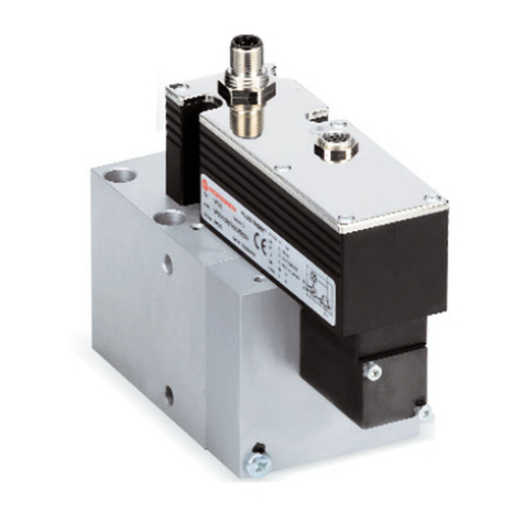
Norgren VP23 Series User manual

Norgren

Norgren VP23 Series User manual

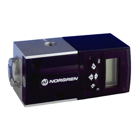
Norgren HERION G1/4 User manual

Norgren

Norgren HERION G1/4 User manual

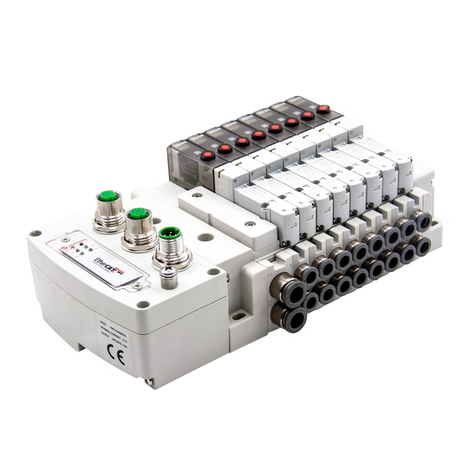
Norgren VP51 User manual

Norgren

Norgren VP51 User manual

Norgren VR10 Instruction Manual

Norgren

Norgren VR10 Instruction Manual

Norgren Prospector A00 5A Series User manual

Norgren

Norgren Prospector A00 5A Series User manual

Norgren VS18 Manual

Norgren

Norgren VS18 Manual

Norgren VP60 Series User manual

Norgren

Norgren VP60 Series User manual

Norgren FD67 User manual

Norgren

Norgren FD67 User manual

Norgren VR10 Installation and operating instructions

Norgren

Norgren VR10 Installation and operating instructions

Popular Control Unit manuals by other brands

Speedaire 4ZL03 Operating instructions & parts manual

Speedaire

Speedaire 4ZL03 Operating instructions & parts manual

YASKAWA CANopen SI-S3/V installation manual

YASKAWA

YASKAWA CANopen SI-S3/V installation manual

Chamberlain LiftMaster GOC1A instructions

Chamberlain

Chamberlain LiftMaster GOC1A instructions

SCP SCIENCE DigiPREP Service manual

SCP SCIENCE

SCP SCIENCE DigiPREP Service manual

Sony IFU-WLM2 user guide

Sony

Sony IFU-WLM2 user guide

Comelit Simplebus Color 5714C Technical manual

Comelit

Comelit Simplebus Color 5714C Technical manual

Allen-Bradley 1336 PLUS II quick start guide

Allen-Bradley

Allen-Bradley 1336 PLUS II quick start guide

fakro ZWMA Usage instructions

fakro

fakro ZWMA Usage instructions

MICRO-EPSILON IF2030/ENETIP operating instructions

MICRO-EPSILON

MICRO-EPSILON IF2030/ENETIP operating instructions

Crestron APAD Operating and installation guide

Crestron

Crestron APAD Operating and installation guide

Hach SC4200c User instructions

Hach

Hach SC4200c User instructions

Geca City CE408P User instructions

Geca

Geca City CE408P User instructions

Ericsson 9D902780G3 Maintenance manual

Ericsson

Ericsson 9D902780G3 Maintenance manual

CALEFFI 5218 Series manual

CALEFFI

CALEFFI 5218 Series manual

Digi XBEE-PRO S3 user guide

Digi

Digi XBEE-PRO S3 user guide

Massoth DiMAX 1210Z manual

Massoth

Massoth DiMAX 1210Z manual

Graco M5 Parts and Accessories Installation Instructions

Graco

Graco M5 Parts and Accessories Installation Instructions

Himoinsa M6 instruction manual

Himoinsa

Himoinsa M6 instruction manual

manuals.online logo
manuals.online logoBrands
  • About & Mission
  • Contact us
  • Privacy Policy
  • Terms and Conditions

Copyright 2025 Manuals.Online. All Rights Reserved.