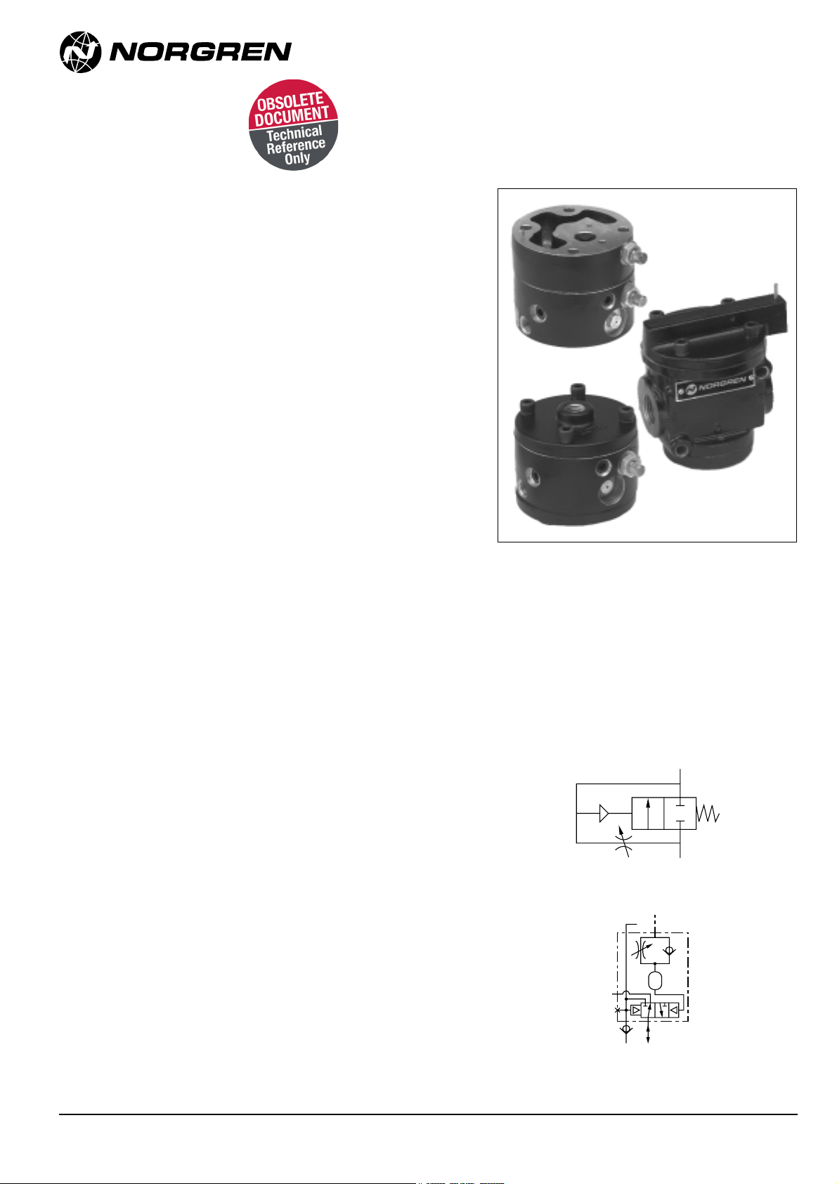
Norgren Prospector A00 5A Series User manual

Prospector®Poppet Valves
Accessories
●Smooth Start Valves available in 2 Basic Body sizes
●1/4"to 1-1/4"port sizes available
●Retards rate of downstream pressure buildup at start up
●Adjustable delay, up to 50 seconds
●Time delays available in two functional models for 0 to 5
and 0 to 60 second delays
●Time Delay on Operate and Time Delay on Release,
normally open and normally closed available
●Can be used in conjunction with most Norgren Poppet
valves
Technical Data
Medium:
Smooth Start Valves: Filtered and lubricated compressed air or
vacuum.
3-Port/2-Position Time Delays: Filtered, nonlubricated dry
compressed air.
Other Time Delays: Filtered (5-micron), nonlubricated, dry
compressed air at a constant pressure and temperature. The
finer the filtration and the closer the regulation, the better the
accuracy and repeatability of the time delay.
Mounting:
Through-holes in valve body, in-line, or on valve.
Port Size:
Smooth Start Valves: 1/4" – 1-1/4" BSPP, PTF, or ISO Rc.
3-Port/2-Position Time Delays: 1/4" BSPP, PTF, or ISO Rc.
Operating Pressure Range:
Smooth Start Valves: 2.1 to 20.7 bar (30 to 300 psig).
3-Port/2-Position Time Delays: 2.1 to 10.3 bar (30 to 150 psig).
Other Time Delays: Equal to or greater than main valve inlet
pressure but not less than 2.1 bar (30 psig) and not greater
than 10.3 bar (150 psig).
Operating Temperature:
Smooth Start Valves: -29° to 79°C (-20° to 75°F).
All Time Delays: 2° to 54°C (35° to 130°F).
Consult Technical Service for use below +2°C (35°F).
Materials:
Body: Aluminum alloy body, acetal, or aluminum check valve,
stainless steel adjusting screw.
Elastomers: Nitrile rubber seals.
Ordering Information
To order poppet valve accessories, quote model
number from Tables overleaf, e.g. order
• A0015C for a 1/2" basic size, 1/2" port size
Smooth Start 2-port, 2-position, spring return,
normally closed valve.
• A104C-04- CE for a 2 port, 2-position spring
return, normally closed Solenoid Pilot Operated
valve fitted with a 0-60 second, normally closed
Time Delay on Release (as indicated by the ‘04’
in the model number).
Smooth Start Valve
Time Delay Model 04
N/** 5.8.291.001
Our policy is one of continued research and development. We therefore reserve the right
to amend, without notice, the specifications given in this document.
10/97
B
(OUT)
A
(IN)
EXH
EPS
IPS MV
SIG
Examples of other models shown on following pages.

3-Port/2-Position Time Delay Valves
NORGREN Time Delay Valves consist of a 0 to 60 second time delay fitted with an A1 air operator and a special bottom cap with IN and
OUT ports. They are used to provide delayed actuation or release of valves or other pneumatic devices that do not require large air flows.
* THREAD: Insert 4for BSPP; 1for PTF; or 6 for ISO Rc.
Prospector®Poppet Valves
N/** 5.8.291.002 Our policy is one of continued research and development. We therefore reserve the right
to amend, without notice, the specifications given in this document. 10/97
Smooth Start Valves
NORGREN Smooth Start Valves are 2-port/2-position, spring return, normally closed valves. They are used in compressed air systems to retard the
rate of downstream pressure buildup at start up. Cylinders and other air operated devices are eased into positions corresponding to initial system
pressurization, reducing the possibility of equipment damage and hazards to the user. Application of full downstream pressure can be delayed for as
long as 50 seconds, depending on the setting of the adjustable needle valve and downstream air volume. Smooth start valves never shut off
completely and must be installed downstream of a directional control valve, such as a NORGREN Poppet Valve listed on the preceding pages.
* THREAD: Insert 4for BSPP; 1for PTF; or 6 for ISO Rc.
Symbol Basic Port CvFactor Model Weight Spares Kit†† For Details
Size Size kg (lbs.) see page
1/4"2.1 A00*5A 0.57 53474-28 6
(1.51)
3/8"3.4 A00*5B 0.57 53474-28 6
(1.51)
1/2"1/2"5.3 A00*5C 0.57 53474-28 6
(1.51)
3/4"6.5 A00*5D 0.57 53474-28 6
(1.51)
3/4"10.7 A00*5E 1.71 53475-26 6
(3.78)
1"1"13.5 A00*5F 1.71 53475-26 6
(3.78)
1-1/4"16.3 A00*5G 1.71 53475-26 6
(3.78)
B
(OUT)
A
(IN)
Symbol Type Port CvFactor Model Weight For Details
Size In to Out Ports OuttoExhaust Ports kg (lbs) see page
Normally Closed, 0.94
Tim Delay on 1/4"0.15 0.16 Z00*2A
Operate (TDO) (2.06)
7
Normally Open, 0.94
Time Delay on 1/4"0.16 0.09 Z00*3A
Operate (TDO) (2.06)
EXH
EPS
IPS MV
SIG
EXH
EPS
IPS MV
SIG

N/** 5.8.291.003
Our policy is one of continued research and development. We therefore reserve the right
to amend, without notice, the specifications given in this document.
10/97
0 to 5 Second Time Delays, & 0 to 60 Second Time Delays - StandardApplications and SpecialApplications
For Use With Air and Solenoid Operated Poppet Valves
Most NORGREN solenoid and air operated poppet valves can be equipped with an adjustable 0 to 5 or 0 to 60 second time delay. Both available in
two functional models.
(1) Time Delay on Operation (TDO), which delays shifting of the main valve poppet on application of the pilot signal, and releases the poppet
immediately upon removal of the signal, and
(2) Time Delay on Release (TDR), which shifts the main valve poppet immediately upon the application of the pilot signal, and delays release
of the poppet on removal of the signal.
Norgren Air Pilot Operated Poppet Valves can be equipped with a Special Application 0 to 60 second One Shot Model, which shifts
the main poppet respectively upon application of the pilot signal and releases the poppet after the time delay period is completed.
Ordering Information
●USE ONLY WITH valves as defined in the following diagram.
●To order valves with a time delay, note the desired valve model number from sections 5.4.291 or 5.4.292. Insert the desired time delay model
number in the 7th and 8th positions of the valve model number as shown in the following diagram. For example: for a 4-Port/2-Position Air Pilot
Operated In-line valve, F1024C-00-A1, with a 0 to 5 Second Time Delay on release order: F1024C-02-A1.
●FOR 0 TO 5 SECOND TIME DELAY - DO NOT USE WITH 2" basic valves.
●FOR 0 TO 60 SECOND ONE SHOT SPECIAL APPLICATION - DO NOT USE WITH 3-way twin valves.
NOTES:
*Valves with an internal pilot supply are identified by a C in the 6th position of the model number. See Figure 1(on following page) for installation.
ALTERNATE CONFIGURATION - MODE - 23 ONE SHOT TIME DELAY: The Alternate Configuration of Model 23 Time Delay (see next page
for description) requires an unrestricted internal pilot supply passage. Select the desired valve model number as described above, then
change the 6th position of the model number to B, e.g. D1022B-23-A1, when ordering Model 23Alternate Configuration. See figure 1 for installation.
When used with valves that have an external pilot supply (designated by an Hor Jin the 6th position of the valve model number), the pilot
supply must be connected to the operator (Figure 2). Zero to five second time delays do not have an external pilot supply port.
** An adjustment screw provides an adjustment range of 0 to 5 or 0 to 60 seconds.
For 0 to 60 second ONLY this range can be extended by increasing the volume of the time delay cavity in the timer body. A port is provided in
the body for connecting an additional external cavity which can consist of a short length of pipe (capped at one end) or other similar air receiver.
Increasing the cavity an additional 29.5 cubic cm., (1.8 cubic inches) will roughly double the delay time for the same adjustment screw setting.
00
Position in Model Number
123456 78 910
Time Delay Models** Weight Spares Kit†† For Details
kg (lbs.) (Nitrile Only) see page
010 to 5 Second 0.31
Time delay on operate. (0.68) 53477-01
020 to 5 Second 0.31
Time delay on release. (0.68)
0 to 60 Second 0.43
03Time delay on operate; (0.95)
Normally closed. 7
0 to 60 Second 0.43
04Time delay on release; (0.95) 53477-03
Normally closed.
0 to 60 Second 0.43
23One Shot Time delay; (0.95)
Normally open.
For 0 to 60 Second, One Shot Models, there must be an A1 or
AA in the 9th and 10th position of the desired model number.
Prospector®Poppet Valves
There must be a C, H,
or Jin the 6th position
of the desired valve
model number.*
There must be an A, B,
C, D, E, or Fin the 1st
position of the desired
valve model number.

N/** 5.8.291.004 Our policy is one of continued research and development. We therefore reserve the right
to amend, without notice, the specifications given in this document. 10/97
Prospector®Poppet Valves
Pilot Air Supply
The pilot air supply to the time delay
must be filtered and regulated as
described under Medium. For best
timer performance, the installation
shown in Figure 2 is recommended.
Connect the external pilot supply to the operator.
The time delay will also be supplied from this connection.
Figure 2. External Pilot Supply
Figure 1. Internal Pilot Supply
Regulator 5-Micron
Filter
Operator
Timer
Main
Valve
Other
Source 5-Micron
Filter Operator
Timer
Main
Valve
Regulator Lubricator
0 to 5 Second Time Delays, & 0 to 60 Second Time Delays - Standard Applications Cont.
Graphic Symbols and Timing Sequences
SIG —Pilot Signal
IPS —Internal Pilot Supply
EPS —External Pilot Supply (Shown Plugged)
EXH —Exhaust
MV —Main Valve (Piston)
ACT —Actuated
REL —Released (Deactuated)
IN PR —Inlet Pressure (Main Valve) —Port/Passage Plugged
—Passage Blocked
IPS MV
SIG
ON
OFF
ACT
REL MV
SIG
(0 to 5 Seconds)
TDR
1. No pilot signal - main valve released.
2. Pilot signal applied - main valve actuates
after the time delay period (TDO) is
completed and remains actuated so long
as the pilot signal is sustained.
3. Pilot signal removed - main valve
released immediately.
1. No pilot signal - main valve released.
2. Pilot signal applied - main valve actuates
immediately and remains actuated so
long as the pilot signal is sustained.
3. Pilot signal removed - main valve
releases after the time delay period (TDR)
is completed.
Model 01 - Time Delay on Operate (TDO) Model 02 - Time Delay on Release (TDR)
1. No pilot signal - main valve released.
2. Pilot signal applied - main valve actuates
after the time delay period (TDO) is
completed and remains actuated so long
as the pilot signal is sustained.
3. Pilot signal removed - main valve released
immediately.
Model 03 - Time Delay on Operate (TDO)
Normally Closed
EXH
EPS
IPS MV
SIG
ON
OFF
ACT
REL MV
SIG
(0 to 60
Seconds)
TDO
IPS MV
SIG
ON
ACT
REL MV
SIG
(0 to 5 Seconds)
TDO
1. No pilot signal - main valve released.
2. Pilot signal applied - main valve actuates
immediately, then releases after the time
delay period (one shot) is completed and
remains released.
3. Pilot signal removed - main valve remains
released.
EXH
MV
SIG
ON
OFF
ACT
REL MV
SIG
(0 to 60
Seconds)
ONE
SHOT
Model 23 One Shot, Normally Open
Standard Configuration
1. Main valve inlet pressurized - main valve
actuates immediately, then releases after
the time delay period (one shot) is com-
pleted and remains released.
2. Main valve inlet pressure reduced to zero
psig - main valve remains released.
Model 23 One Shot, Normally Open
Alternate Configuration
EXH
MV
SIG
ON
OFF
ACT
REL MV
SIG
(0 to 60
Seconds)
TDO
1. No pilot signal - main valve released.
2. Pilot signal applied - main valve actuates
immediately and remains actuated so long
as the pilot signal is sustained.
3. Pilot signal removed - main valve releases
after the time delay period (TDR) is
completed.
Model 04 - Time Delay on Release
(TDR) Normally Closed
EXH
EPS
IPS MV
SIG
ON
OFF
ACT
REL MV
SIG
(0 to 60
Seconds)
TDR
Internal pilot supply Shut off air supply to main valve. Cycle valve operator until trapped air is exhausted from the main valve piston chamber, operator, and time delay.
You may also install a 2-way vent valve on the external pilot supply port.
External pilot supply Shut off air supply to main valve and the pilot supply. Cycle the valve operator until the trapped air is exhausted. You may also install a 2-way
vent valve on external pilot supply line.

N/** 5.8.291.005
Our policy is one of continued research and development. We therefore reserve the right
to amend, without notice, the specifications given in this document.
10/97
WARNING
These products are intended for use in industrial compressed air systems only. Do not use these products where pressures and temperatures
can exceed those listed under ‘Technical Data’.
Before using these products with fluids other than those specified, for non-industrial applications, life support systems, or other applications not
within published specifications, consult Norgren.
Through misuse, age, or malfunction, components used in fluid power systems can fail in various modes. The system designer is warned to con-
sider the failure modes of all component parts
used in fluid power systems and to provide adequate safeguards to prevent personal injury or damage to equipment in the event of such failure.
Systems designers must provide a warning to end users in the system instructional manual if protection against a failure mode cannot be ade-
quately provided.
System designers and end users are cautioned to review specific warnings found in instruction sheets packed and shipped with these products
where applicable.
WARRANTY
AIl items sold by NORGREN Valves are warranted tobe free from defects in materials and workmanship for a period of two years from the date of
manufacture, provided said items are used according to NORGREN’s recommended usages. NORGREN’s liability is limited to the repair of, refund
of purchase price paid for, or replacement in kind of, at NORGREN’s sole option, any items proved defective, provided the allegedly defective items
are returned to NORGREN prepaid. The warranties expressed above are in lieu of and exclusive of all other warranties. There are no other war-
ranties, expressed or implied, except as stated herein.
There are no implied warranties of merchantability or fitness for a particular purpose, which are specifically disclaimed. NORGREN’s liabil-
ity for breach of warranty as herein stated is the exclusive remedy, and in no event shall NORGREN be liable or responsible for incidental or
consequential damages, even if the possibility of such incidental or consequential damages has been made known to NORGREN.
NORGREN reserves the right to discontinue manufacture of any product or change product materials, design, or specifications.
Prospector®Poppet Valves

Prospector®Poppet Valves
Smooth Start Valves Dimensions
Dimensions in mm (inches).
Basic 1/2-Inch A00*5A, A00*5B, A00*5C & A00*5D.
38.1 (1.50)
*52.3 (2.06)
76.2 (3.00)
39.5 (1.56)
77.7 (3.06)
63.5 (2.50)
96.0 (3.74)
57.9 (2.28)
0.84 (2.13)
Adjustment Screw
57.9 (2.28)
42.2 (1.66)
7.1 (0.28)
Dia. (2 pics) 0.84 (2.13)
25.4 (1.00)
1/4", 3/8", 1/2", 3/4"*
1/4", 3/8", 1/2", 3/4"*
Basic 1-Inch A00*5E, A00*5F & A00*5G.
58.7 (2.31)
117.3 (4.62)
84.1 (3.31)
52.3 (2.06)
104.1 (4.10)
28.7 (1.13)
73.2 (2.88)
153.4 (6.04)
101.1 (3.98)
101.1 (3.98)
69.3 (2.73)50.5 (2.38)
Adjustment Screw
10.4 (0.41)
Dia. (2 pics)
*
3/4", 1", 1-1/4"* 3/4", 1", 1-1/4"*
N/** 5.8.291.006 Our policy is one of continued research and development. We therefore reserve the right
to amend, without notice, the specifications given in this document. 10/97
* After final adjustment, drive pin in until flush to make adjustment tamper resistant.

N/** 5.8.291.007
Our policy is one of continued research and development. We therefore reserve the right
to amend, without notice, the specifications given in this document.
10/97
Time Delay Valve Dimensions
Dimension in mm (inches).
54 (2.13)
72 (2.84)
78 (3.06)
Adjustment
Screw
Exhaust 1/8"
Do Not
Restrict
18
(0.69) 18
(0.69)
1/4"
1/4"
Adjustment
Screw
78 (3.06)
54 (2.13)
26 (1.03)
Adjustment
Screw
External Pilot Supply Port
1/8"
78 (3.06)
54 (2.13)39 (1.53)
Exhaust Port
1/8"
Do Not
Restrict
External Cavity Port
1/8"
Models 03, 04, 23
Models 01, 02
0 to 5 Second Time Delays 0 to 60 Second Time Delays
3-Port/2-Position Time Delays
Prospector®Poppet Valves
This manual suits for next models
8
Table of contents
Other Norgren Control Unit manuals

Norgren
Norgren VP23 Series User manual

Norgren
Norgren VP60 Series User manual

Norgren
Norgren HERION G1/4 User manual

Norgren
Norgren VP51 User manual

Norgren
Norgren VR10 Installation and operating instructions

Norgren
Norgren VS18 Manual

Norgren
Norgren 82 Series User manual

Norgren
Norgren VR10 Instruction Manual

Norgren
Norgren FD67 User manual
Popular Control Unit manuals by other brands

ThingMagic
ThingMagic M5e Hardware guide

Pego
Pego VISION100 THR Use and maintenance manual

Chamberlain
Chamberlain LiftMaster Professional CB124 instructions

ESD
ESD CAN-CBM-REL4 Hardware manual

Texas Instruments
Texas Instruments CDCM1804 user guide

SMC Networks
SMC Networks S0700 Installation and maintenance manual