Norgren VS18 Manual

VS18/VS26 VALVE ADVANTAGE
MAINTENANCE & INSTRUCTION BOOKLET
VS2672926-KG00E
REVISION E
MAY 2007

VS18/VS26 MAINTENANCE & INSTRUCTION BOOKLET
1 CONTENT
1CONTENT ..............................................................................................................................................2
2VS18/VS26-SYSTEM OVERVIEW ...........................................................................................................5
3SAFETY, WARNING ................................................................................................................................6
4TECHNICAL DATA...................................................................................................................................8
4.1 SPECIFICATION ..................................................................................................................................8
4.1.1 Ambient temperature ............................................................................................................................. 8
4.1.2 Medium temperature.............................................................................................................................. 8
4.1.3 Medium.................................................................................................................................................. 8
4.1.4 Air quality............................................................................................................................................... 8
4.2 MATERIALS........................................................................................................................................9
4.3 PNEUMATIC .....................................................................................................................................10
4.3.1 Response times VS valves .................................................................................................................. 10
4.3.2 Flow..................................................................................................................................................... 11
4.3.3 Maximum cycling rate .......................................................................................................................... 11
4.3.4 Minimum impulse on bistable valves ................................................................................................... 11
4.3.5 Important information for 2x2/2 valves................................................................................................. 11
4.4 ELECTRICAL ....................................................................................................................................12
4.4.1 Voltage tolerances ............................................................................................................................... 12
4.4.2 Required performance of power supply unit ........................................................................................ 12
4.4.3 Power supply and precautions............................................................................................................. 12
4.5 COMPLIANCE AND APPROVALS..........................................................................................................13
4.5.1 CE marking.......................................................................................................................................... 13
4.5.2 ATEX (Directive 94/9/EC) for 24V DC only.......................................................................................... 13
4.5.3 ISO standard ....................................................................................................................................... 14
4.5.4 Fieldbus standards .............................................................................................................................. 14
4.5.5 CNOMO standard................................................................................................................................ 14
4.5.6 DIN standard ....................................................................................................................................... 14
4.5.7 UL/CSA approval................................................................................................................................. 14
5INSTALLATION AND MAINTENANCE MECHANICAL.....................................................................................15
5.1 INSTALLATION ..................................................................................................................................15
5.1.1 Tools.................................................................................................................................................... 15
5.1.2 Tightening torque................................................................................................................................. 15
5.1.3 Port identification ................................................................................................................................. 16
5.1.4 Assembly of VS18/VS26 valve islands ................................................................................................ 17
5.1.5 Valve identification labels .................................................................................................................... 21
5.1.6 Internal/external pilot air supply ........................................................................................................... 22
5.1.7 Multi pressure ...................................................................................................................................... 23
5.1.8 DIN-rail assembly ................................................................................................................................ 24
5.1.9 Installation instruction in case of raised vibrations ............................................................................... 25
5.1.10 Sandwich plates................................................................................................................................... 26
5.1.11 Replacement of valves ........................................................................................................................ 28
5.1.12 Replacement of pilot valves................................................................................................................. 29
5.1.13 Manual override set-up kit ................................................................................................................... 30
5.1.14 Blanking plug for base connector hole................................................................................................. 31
5.2 MAINTENANCE .................................................................................................................................32
5.2.1 Lubrication ........................................................................................................................................... 32
5.2.2 Spare parts .......................................................................................................................................... 33
6SINGLE STATION SUB-BASE ..................................................................................................................34
6.1 GENERAL INFORMATION ...................................................................................................................34
6.1.1 24V DC power supply .......................................................................................................................... 34
6.1.2 115V AC power supply ........................................................................................................................ 34
6.1.3 Max current load on valve connectors with 24V DC ............................................................................ 34
6.1.4 Max current load on valve connectors with 115V AC........................................................................... 34
6.2 VARIANT WITH M12 CONNECTOR......................................................................................................35
6.2.1 Pin assignment (acc. VDMA 24571) .................................................................................................... 35
6.3 VARIANT WITH NPTF1/2“ CONDUIT WITH FLYING LEADS .....................................................................36
6.3.1 Wiring information................................................................................................................................ 36
VS2672926-KG00E_05/07 Page 2/97

VS18/VS26 MAINTENANCE & INSTRUCTION BOOKLET
7MULTIPOLE..........................................................................................................................................37
7.1 GENERAL INFORMATION....................................................................................................................37
7.1.1 24V DC power supply...........................................................................................................................37
7.1.2 115V AC power supply.........................................................................................................................37
7.1.3 Max current load on valve connectors with 24V DC .............................................................................37
7.1.4 Max current load on valve connectors with 115V AC ...........................................................................37
7.2 VARIANTS WITH D-SUB CONNECTORS ...............................................................................................38
7.2.1 D-Sub assembly / Installation of PCB...................................................................................................38
7.2.2 Pin assignment.....................................................................................................................................39
7.3 VARIANT WITH NPTF1” CONDUIT ENTRY WITH TERMINALS ..................................................................42
7.3.1 NPTF1” conduit entry with terminals assembly / Installation of PCB ....................................................42
7.3.2 Pin assignment.....................................................................................................................................44
7.4 VARIANT WITH M23 CONNECTOR ......................................................................................................45
7.4.1 M23 assembly / Installation of PCB......................................................................................................45
7.4.2 Pin assignment.....................................................................................................................................46
8FIELDBUS............................................................................................................................................47
8.1 GENERAL INFORMATION....................................................................................................................47
8.1.1 Power supply and pin assignment ........................................................................................................48
8.1.2 Max. current load on valve connectors.................................................................................................48
8.1.3 Fieldbus assembly / Installation of PCBs (excluding AS-Interface and FD67 bus)...............................49
8.1.4 AS-Interface assembly / Installation of PCBs .......................................................................................50
8.1.5 FD67 bus assembly / Installation of PCB .............................................................................................51
8.2 PROFIBUS DP..................................................................................................................................52
8.2.1 Profibus DP pin assignment .................................................................................................................52
8.2.2 Profibus DP wiring................................................................................................................................53
8.2.3 Profibus DP address and baud rate setting..........................................................................................55
8.2.4 Profibus DP output addressing.............................................................................................................56
8.2.5 Diagnostics...........................................................................................................................................57
8.2.6 Profibus DP LED indicators..................................................................................................................57
8.2.7 Profibus DP commissioning..................................................................................................................57
8.2.8 GSD file................................................................................................................................................58
8.2.9 Profibus DP valve island expansion .....................................................................................................58
8.2.10 More information on Profibus DP .........................................................................................................58
8.3 DEVICENET .....................................................................................................................................59
8.3.1 DeviceNet pin assignment....................................................................................................................59
8.3.2 DeviceNet wiring ..................................................................................................................................59
8.3.3 DeviceNet address and baud rate setting.............................................................................................61
8.3.4 DeviceNet output addressing ...............................................................................................................61
8.3.5 Diagnostics...........................................................................................................................................62
8.3.6 DeviceNet LED indicators ....................................................................................................................62
8.3.7 DeviceNet EDS files and commissioning..............................................................................................63
8.3.8 DeviceNet valve island expansion........................................................................................................64
8.3.9 More information on DeviceNet ............................................................................................................64
8.4 CANOPEN .......................................................................................................................................65
8.4.1 CANopen pin assignment.....................................................................................................................65
8.4.2 CANopen wiring ...................................................................................................................................66
8.4.3 CANopen address and baud rate setting..............................................................................................67
8.4.4 CANopen output addressing ................................................................................................................68
8.4.5 Diagnostics...........................................................................................................................................68
8.4.6 CANopen LED indicators .....................................................................................................................69
8.4.7 CANopen commissioning .....................................................................................................................70
8.4.8 CANopen valve island expansion.........................................................................................................70
8.4.9 More information on CANopen .............................................................................................................70
8.5 INTERBUS-S ....................................................................................................................................71
8.5.1 Interbus-S pin assignment....................................................................................................................71
8.5.2 Interbus-S wiring ..................................................................................................................................72
8.5.3 Interbus-S address and baud rate setting ............................................................................................72
8.5.4 Interbus-S output addressing ...............................................................................................................72
8.5.5 Diagnostics...........................................................................................................................................72
8.5.6 Interbus-S LED indicators ....................................................................................................................73
8.5.7 Interbus-S ID and length codes ............................................................................................................74
8.5.8 Interbus-S commissioning ....................................................................................................................75
8.5.9 Interbus-S valve island expansion........................................................................................................75
8.5.10 More information on Interbus-S ............................................................................................................75
VS2672926-KG00E_05/07 Page 3/97

VS18/VS26 MAINTENANCE & INSTRUCTION BOOKLET
8.6 AS-INTERFACE ................................................................................................................................76
8.6.1 AS-Interface pin assignment................................................................................................................ 76
8.6.2 AS-Interface wiring .............................................................................................................................. 77
8.6.3 AS-Interface address and baud rate setting ........................................................................................ 77
8.6.4 AS-Interface single slave valve island configurations and settings ...................................................... 78
8.6.5 AS-Interface single slave output addressing........................................................................................ 78
8.6.6 AS-Interface double slave valve island configurations and settings..................................................... 79
8.6.7 AS-Interface double slave output addressing ...................................................................................... 80
8.6.8 Diagnostics .......................................................................................................................................... 81
8.6.9 AS-Interface LED indicators ................................................................................................................ 81
8.6.10 AS-Interface ID and I/O configuration codes ....................................................................................... 82
8.6.11 AS-Interface commissioning ................................................................................................................ 82
8.6.12 AS-Interface valve island expansion.................................................................................................... 82
8.6.13 More information on AS-Interface........................................................................................................ 82
8.7 FD67 BUS .......................................................................................................................................83
8.7.1 FD67 bus pin assignment .................................................................................................................... 83
8.7.2 Wiring termination................................................................................................................................ 84
8.7.3 FD67 bus output addressing................................................................................................................ 84
8.7.4 FD67 bus LED indicators and diagnostics ........................................................................................... 85
8.7.5 FD67 bus commissioning .................................................................................................................... 85
8.7.6 FD67 Profibus GSD file ....................................................................................................................... 85
8.7.7 FD67 DeviceNet EDS file .................................................................................................................... 86
8.7.8 FD67 CANopen EDS file ..................................................................................................................... 86
8.7.9 FD67 valve island expansion ............................................................................................................... 86
8.7.10 More information on FD67 ................................................................................................................... 86
9VALVE ISLAND EXPANSION....................................................................................................................87
9.1 GENERAL INFORMATION ...................................................................................................................87
9.2 ASSEMBLY OF SINGLE ADD-ON STATIONS FOR MULTIPOLE AND FIELDBUS VALVE ISLANDS ....................88
10 USE IN AREAS WITH POTENTIALLY EXPLOSIVE ATMOSPHERE (94/9/EC „ATEX“) – OPERATING MANUAL AND
DECLARATION OF CONFORMITY.............................................................................................................90
10.1 INTENDED USAGE .............................................................................................................................90
10.2 OPERATING MANUAL ATEX .............................................................................................................90
10.2.1 General conditions............................................................................................................................... 90
10.2.2 Installation ........................................................................................................................................... 91
10.2.3 Operating............................................................................................................................................. 91
10.2.4 Failures................................................................................................................................................ 92
10.2.5 Maintenance and repair ....................................................................................................................... 92
10.3 ATEX CONFORMITY .........................................................................................................................93
10.3.1 Operating conditions............................................................................................................................ 93
10.3.2 Labels .................................................................................................................................................. 93
10.3.3 Specific conditions ............................................................................................................................... 94
10.3.4 Declaration of conformity ..................................................................................................................... 94
11 TRANSPORT / STORAGE / PACKAGING ...................................................................................................96
12 REVISION INDEX...................................................................................................................................97
VS2672926-KG00E_05/07 Page 4/97

VS18/VS26 MAINTENANCE & INSTRUCTION BOOKLET
2 VS18/VS26-SYSTEM OVERVIEW
24V DC or 115V AC Multipole
Integrated Fieldbus
Field expandable with single add-on stations
Dual spool technology
VS18G/VS26G Glandless spool and sleeve
for long life
VS18S/VS26S Softseal spool
for high flow
Wide range of accessories
UL and ATEX
Universal PNP/NPN 24V DC Multipole
Please find ordering information of all components in the data sheets 5.4.159 (VS18) and
5.4.160 (VS26).
VS2672926-KG00E_05/07 Page 5/97

VS18/VS26 MAINTENANCE & INSTRUCTION BOOKLET
3 SAFETY, WARNING
These products are intended for use in industrial compressed air or hydraulic systems only. Do
not use these products where pressures and temperatures can exceed those listed under
‘Technical Data’.
Before using these products with fluids other than those specified, for non-industrial
applications, life-support systems, or other applications not within published specifications,
consult NORGREN. Through misuse, age, or malfunction, components used in fluid power
systems can fail in various modes. The system designer is warned to consider the failure modes
of all component parts used in fluid power systems and to provide adequate safeguards to
prevent personal injury or damage to equipment in the event of such failure.
System designers must provide a warning to end users in the system instructional
manual if protection against a failure mode cannot be adequately provided. System
designers and end users are cautioned to review specific warnings found in instruction sheets
packed and shipped with these products.
Specific warnings:
• Check if classification of the valve island and marking on the item of equipment are able for
case of operation.
• Check technical data, such as operating pressure, voltage level, current type and
temperature, on the product label or in the data sheets for compliance with the existing
operating conditions.
• After removing the packaging, make sure that no contamination enter into the system.
• Check before the installation of the system that no contamination exists in the piping and
valve island.
• Check during installation of the system that gaskets will not become damaged.
• Please consider the information of this operating manual as well as the use conditions and
permissible data, which are on the product labels.
• Adapt to the general rules of technology when selecting and using an item of equipment.
• Take measures to avoid unintentional or improper activation.
• Prior to the first electrical operation, ensure no danger would result from the medium
exhausting from any open ports.
• Consider in case of pressurised systems that lines, valves and other components should not
be removed.
• ATTENTION: There is some risk of injury! The surface of pilot valves could become very
warm in continuous operation.
• ATTENTION: Valves with NO function (normally open) are open without pilot pressure.
During commissioning, protection against exhausted medium has to be provided.
• Leak and strength tests on open and closed valves are admissible until max. 1.5 times the
max. operating pressure. It is not allowed to operate the valve during these tests.
• Never use the valve island as lever arm or a step for climbing.
• Protect the valve island from falling objects.
VS2672926-KG00E_05/07 Page 6/97

VS18/VS26 MAINTENANCE & INSTRUCTION BOOKLET
• Any fitting position of the valve island is permissible but valves with indicating lights up is
preferred.
• To avoid damaging the product, please make sure that the maximum torque values are not
exceeded (see section 5.1.2).
• Avoid short-circuits and breaks by not deviating from the standard use of connector cables
and cords.
• Order spare parts with the part number indicated on the product labels. (See section 5.2.2
and/or data sheets 5.4.159 (VS18) resp. 5.4.160 (VS26)).
• Do not load the system by bending or torsion.
• Important: Power must be removed from the system while assembling and disassembling
electrical connectors, plugs and cables, valves, sandwich plates and blanking plates.
• Install and use only complete configured and connected valve islands.
• VS18/VS26 Fieldbus valve islands contain electronic devices, which could be damaged
through electrostatic discharge. Therefore electrostatic precautions must be taken.
Specifically, the person assembling or configuring the valve island must be connected to an
earth ground.
• Please refer to section 4.4.3 for information on power supply and earth ground connection of
Multipole and Fieldbus valve islands.
• Use this booklet or the instruction sheets packed with the product for assembling and
installation.
VS2672926-KG00E_05/07 Page 7/97

VS18/VS26 MAINTENANCE & INSTRUCTION BOOKLET
4 TECHNICAL DATA
For more information, please refer to data sheets 5.4.159 (VS18) and 5.4.160 (VS26).
4.1 SPECIFICATION
4.1.1 Ambient temperature
-15°C to +50°C
(Consult our technical service for use below +2°C.)
4.1.2 Medium temperature
-5°C to +50°C
4.1.3 Medium
The valves of these series are intended for use with compressed air only.
The valves must be operated within the pressure range specified in the data sheets 5.4.159
(VS18) and 5.4.160 (VS26).
4.1.4 Air quality
The valves are designed for filtered (40µm), lubricated or non-lubricated compressed air.
(Please find details on oils in section 5.2.1.) If the air supply is lubricated, then lubrication must
be supplied for the life of the product.
VS2672926-KG00E_05/07 Page 8/97

VS18/VS26 MAINTENANCE & INSTRUCTION BOOKLET
4.2 MATERIALS
Valve body / sub-bases: Die-cast aluminium
Glandless spool&sleeve (VS**G): Aluminium, hard anodised, teflon coated
Softseal spool (VS**S): Aluminium with HNBR seals
Plastic parts: POM, PA, PPA
Mounting sheets / screws: steel, zinc coated
Springs: stainless steel
Seals: NBR
Sandwich plates: Aluminium bar material, PA
Electrical contacts: brass, tin/gold coated
PCB: Glasepoxy
VS2672926-KG00E_05/07 Page 9/97

VS18/VS26 MAINTENANCE & INSTRUCTION BOOKLET
4.3 PNEUMATIC
4.3.1 Response times VS valves
The response measurements are taken according to ISO 12238 standard.
Glandless valves VS**G VS18 VS26
Response
time ON (ms)
Response
time OFF (ms)
Response
time ON (ms)
Response
time OFF (ms)
5/2 Sol/Spring 18 54 24 58
5/2 Sol/Sol 18 18 20 20
5/2 Sol (priority side 14)/Sol 141) 212) 141) 212)
5/3 APB Sol/Sol 24 37 26 52
5/3 COE Sol/Sol 25 49 28 52
Softseal valves VS**S VS18 VS26
Response
time ON (ms)
Response
time OFF (ms)
Response
time ON (ms)
Response
time OFF (ms)
2x2/2 NC Sol/Sol 24 21 29 29
2x2/2 NO Sol/Sol 24 21 29 29
2x2/2 NO/NC Sol/Sol 24 21 29 29
2x3/2 NC Sol/Sol 20 22 32 25
2x3/2 NO Sol/Sol 20 22 32 25
2x3/2 NO/NC Sol/Sol 20 22 32 25
5/2 Sol/Spring 16 42 18 46
5/2 Sol/Sol 14 14 14 14
5/3 APB Sol/Sol 18 40 20 55
5/3 COE Sol/Sol 18 40 19 55
1) ON side 14
2) ON side 12
APB = All ports blocked
COE = Centre open exhaust
NC = Normally closed
NO = Normally open
VS2672926-KG00E_05/07 Page 10/97

VS18/VS26 MAINTENANCE & INSTRUCTION BOOKLET
4.3.2 Flow
The flow values are measured at 6 bar inlet pressure and with a pressure drop of 1 bar.
Glandless valves VS**G VS18 VS26
QN
(L/min)
Kv
(m3/h)
Cv (US
Gal/min)
QN
(L/min)
Kv
(m3/h)
Cv (US
Gal/min)
5/2 Sol/Spring 550 0.48 0.56 1‘000 0.87 1.02
5/2 Sol/Sol 550 0.48 0.56 1‘000 0.87 1.02
5/2 Sol (priority side 14)/Sol 550 0.48 0.56 1‘000 0.87 1.02
5/3 APB Sol/Sol 550 0.48 0.56 1‘000 0.87 1.02
5/3 COE Sol/Sol 550 0.48 0.56 1‘000 0.87 1.02
Softseal valves VS**S VS18 VS26
QN
(L/min)
Kv
(m3/h)
Cv (US
Gal/min)
QN
(L/min)
Kv
(m3/h)
Cv (US
Gal/min)
2x2/2 NC Sol/Sol 550 0.46 0.56 1’150 1.00 1.17
2x2/2 NO Sol/Sol 550 0.46 0.56 1’150 1.00 1.17
2x2/2 NO/NC Sol/Sol 550 0.46 0.56 1’150 1.00 1.17
2x3/2 NC Sol/Sol 600 0.52 0.61 1‘250 1.09 1.27
2x3/2 NO Sol/Sol 600 0.52 0.61 1‘250 1.09 1.27
2x3/2 NO/NC Sol/Sol 600 0.52 0.61 1‘250 1.09 1.27
5/2 Sol/Spring 650 0.57 0.66 1‘350 1.18 1.37
5/2 Sol/Sol 650 0.57 0.66 1‘350 1.18 1.37
5/3 APB Sol/Sol 650 0.57 0.66 1‘350 1.18 1.37
5/3 COE Sol/Sol 650 0.57 0.66 1‘350 1.18 1.37
APB = All ports blocked
COE = Centre open exhaust
NC = Normally closed
NO = Normally open
4.3.3 Maximum cycling rate
In practice the cycling rate should be lower than 300 c.p.m. (<5 Hz). The valves should be
switched above 90% (working port) and below 10% (exhausting port) of the supply pressure.
4.3.4 Minimum impulse on bistable valves
The minimum impulse length on 5/2 way bistable valves should correspond at least twice to the
response time (see section 4.3.1).
4.3.5 Important information for 2x2/2 valves
All 2x2/2 functions (NC, NO or NO/NC) have port 1 not connected in neither end position to port
2 or 4. Port 1 is not necessary (except internal pilot air). Supply of compressed air or vacuum
must be feeded to port 3 or 5.
Pay attention to this when configuring the valve island (blanking off canals 3 and 5 in base) !!
VS2672926-KG00E_05/07 Page 11/97

VS18/VS26 MAINTENANCE & INSTRUCTION BOOKLET
4.4 ELECTRICAL
4.4.1 Voltage tolerances
Voltage Voltage tolerances
24V DC +/-10%
115V AC -10%/+15%
4.4.2 Required performance of power supply unit
The required performance can be calculated from the maximum number of energized solenoids
at the same time. In case of a Fieldbus valve island the consumption of power of the electronic
has to be considered (see section 8).
4.4.3 Power supply and precautions
All VS18/VS26 24V DC products are designed to be used with a protective extra low voltage
(PELV) power supply (UL Class 2 Supply only).
All VS18/VS26 115V AC products correspond to the protection class I. Connection of the
protective earth (PE) ground is required.
VS2672926-KG00E_05/07 Page 12/97

VS18/VS26 MAINTENANCE & INSTRUCTION BOOKLET
4.5 COMPLIANCE AND APPROVALS
The VS18/VS26 products are tested and compliant:
4.5.1 CE marking
Degrees of protection provided by enclosures (IP code):
EN 60529:91+A1:00 (IEC 60529:89 + A1:99)
Low-voltage switchgear and controlgear:
EN 60947-5-1: 97+A1:00+A2:00+A12:00 - Control circuit devices and switching elements
EN 60947-1: 99+A1:00+A2:01 - Electromechanical control circuit devices
Electromagnetic compatibility (EMC directive 89/336/EEC):
EN 61000-6-2: 01 - Immunity for industrial environments
EN 61000-6-4: 01 - Emission standard for industrial environments
Vibrations- and shock test:
DIN EN 60 068-2-6 - Vibration resistance (Test Fc: Vibration (sinusoidal))
DIN EN 60 068-2-27 (30g) - Shock resistance (Test Ea and guidance: Shock)
4.5.2 ATEX (Directive 94/9/EC) for 24V DC only
EN 50021:99 - Electrical apparatus for potentially explosive atmospheres - Type of
protection "n"
EN 13463-1:02 - Non-electrical equipment for potentially explosive atmospheres. Part 1.
Basic methodology and requirements.
EN 50281-1-1:99 - Electrical apparatus for use in the presence of combustible dust - Part 1-1:
Electrical apparatus protected by enclosures - Construction and testing
EN 1127-1:97 - Explosive atmospheres – Explosion prevention and protection – Part 1 :
Basic concepts and methodology.
For more information please refer to section 10.
VS2672926-KG00E_05/07 Page 13/97

VS18/VS26 MAINTENANCE & INSTRUCTION BOOKLET
4.5.3 ISO standard
ISO 15407-2 (size 26mm and 18mm)
4.5.4 Fieldbus standards
Norgren Profibus DP Fieldbus systems conform to
DIN 19245 part 3.
Norgren DeviceNet systems conform to
DeviceNet specification volume 1 release 2 and the Pneumatic Valve Device Profile.
Norgren CANopen Fieldbus systems conform to
CANopen communication profile CiA DS-301 V4.0.
Norgren Interbus-S Fieldbus systems conform to
DIN 19258.
Norgren AS-Interface Fieldbus systems conform to
AS-I V2.11 specification.
For detailed information on Fieldbus protocols please refer to section 8.
4.5.5 CNOMO standard
The M23 19-pin connector fulfils CNOMO standard E03.62.530.N.
For more information on this standard please refer to the CNOMO website www.cnomo.com.
For more information on the M23 19-pin connector please refer to section 7.4.
4.5.6 DIN standard
Colour code of D-Sub connectors according DIN 47100
4.5.7 UL/CSA approval
Investigated to UL 429 - 5th edition & CSA 22.2 No.139 - 1982 for 24V DC electrically operated
valves.
VS2672926-KG00E_05/07 Page 14/97

VS18/VS26 MAINTENANCE & INSTRUCTION BOOKLET
5 INSTALLATION AND MAINTENANCE MECHANICAL
5.1 INSTALLATION
5.1.1 Tools
VS18:
• Hexagon wrench key 2mm
• Hexagon wrench key 2.5mm
• Socket screw key X10
• Philips screwdriver size 1
• Screwdriver size 1
VS26:
• Hexagon wrench key 3mm
• Socket screw key X10
• Philips screwdriver size 1
• Screwdriver size 1
5.1.2 Tightening torque
To avoid damaging the product, please make sure that the maximum torque values are not
exceeded. The maximum torques are specified in the particular installation instructions.
Valve mounting screws
The valve mounting screws are pressurised. To prevent leakage through the mounting screws,
screws with blue coated thread are used. The specified torques for the blue coated screws
reduce to standard values after first use of the screws. These screws should not be used more
than five times, as good sealing performance can then not be guaranteed.
VS2672926-KG00E_05/07 Page 15/97

VS18/VS26 MAINTENANCE & INSTRUCTION BOOKLET
5.1.3 Port identification
On all end plates and modular sub-bases each port is marked as follows:
Function Port/Identification
Main/internal pilot air supply 1
Exhaust 3 + 5
Outlet 2 + 4
External pilot air supply (if used) 12/14
Collected exhaust of pilot valves 82/84
Note:
Never plug port 82/84. Plugging this port will cause valves to malfunction.
port 1 port 82/84
port 12/14
port 2
port 5
port 4
port 3
VS2672926-KG00E_05/07 Page 16/97

VS18/VS26 MAINTENANCE & INSTRUCTION BOOKLET
5.1.4 Assembly of VS18/VS26 valve islands
Tools:
VS18: Hexagon wrench key 2.5mm
Philips screwdriver size 1
VS26: Hexagon wrench key 3mm
Philips screwdriver size 1
To assemble a complete valve island, make sure you have ordered all necessary components
and the required tools are available.
1. First bolt all modular sub-bases together. Ensure sub-bases are properly aligned and the
gasket is fitted between the sub-bases. Then tighten the mounting screws (two per modular
sub-base) with the specified torque. If you are using a power screwdriver, consider the
maximum speed allowed.
For multi pressure applications, please refer to section 5.1.7.
Note:
When ordering an even number of stations, please ensure the valve island contains a
maximum of two single station modular sub-bases. E.g.: You order an 8-station Multipole
valve island with an 8-station main PCB. The valve island must have at least three double
station modular sub-bases and must have no more than two single station modular sub-
bases.
When ordering an odd number of stations, the single station modular sub-base should be at
the right end of the valve island. In addition, you can use two additional single station
modular sub-bases, for a total of three.
Screw Type
(thread) Valve
seize Tightening
torque in Nm Tightening
torque in Ibs Max. screw driver
speed in r.p.m.
11 M3x10 VS18 0.8 – 0.9 7.08 – 7.96 1100
11 M4x12 VS26 1.0 – 1.1 8.85 – 9.73 1100
VS2672926-KG00E_05/07 Page 17/97

VS18/VS26 MAINTENANCE & INSTRUCTION BOOKLET
2. Mount the left and right end plate to the modular sub-base. Ensure end plates are properly
aligned and the end plate gasket is fitted. Then tighten the mounting screws (two per end
plate) with the specified torque. If you are using a power screwdriver, consider the maximum
speed allowed.
Screw Type
(thread) Valve
seize Tightening
torque in Nm Tightening
torque in Ibs Max. screw driver
speed in r.p.m.
11 M3x10 VS18 0.8 – 0.9 7.08 – 7.96 1100
11 M4x12 VS26 1.0 – 1.1 8.85 – 9.73 1100
3. Having assembled the base of the valve island, proceed with the electronic components. For
these instructions please refer to following sections:
7.2.1 D-Sub assembly / Installation of PCB
7.3.1 NPTF1” conduit entry with terminals assembly / Installation of PCB
7.4.1 M23 assembly / Installation of PCB
8.1.3 Fieldbus assembly / Installation of PCBs (excluding AS-Interface and FD67 bus)
8.1.4 AS-Interface assembly / Installation of PCBs
8.1.5 FD67 bus assembly / Installation of PCB
VS2672926-KG00E_05/07 Page 18/97

VS18/VS26 MAINTENANCE & INSTRUCTION BOOKLET
4. Lastly, mount the valves, sandwich plates, blanking plates and/or intermediate
supply/exhaust modules.
Valves:
1. Ensure valve body gasket is fitted on the bottom of the valve. Place valve onto the
modular sub-base aligned to the interface. Use plug-in connection as positioning point.
2. VS26 only: Orientate straight flange of the U-washers towards the outer edge of the
valve.
3. Tighten the valve mounting screws (two per valve) with the specified torque. If you are
using a power screwdriver, consider the maximum speed allowed.
Screw Type
(thread) Valve
seize Tightening
torque in Nm Tightening
torque in Ibs Max. screw driver
speed in r.p.m.
12 M3x40 VS18 1.1 – 1.5 9.73 – 13.27 1100
12 M4x42 VS26 1.2 – 1.6 10.62 – 14.16 1100
VS2672926-KG00E_05/07 Page 19/97

VS18/VS26 MAINTENANCE & INSTRUCTION BOOKLET
Blanking plate and/or intermediate supply/exhaust module (ISEM):
1. Ensure gasket is fitted on the bottom of the blanking plate or ISEM. Place blanking plate
or ISEM onto the modular sub-base aligned to the interface.
2. Tighten valve mounting screws (two per blanking plate/ISEM) with the specified torque.
If you are using a power screwdriver consider the maximum speed allowed.
Screw Type
(thread) Valve
seize Tightening
torque in Nm Tightening
torque in Ibs Max. screw driver
speed in r.p.m.
18 M3x14 VS18 0.8 – 0.9 7.08 – 7.96 1100
18 M4x16 VS26 1.0 – 1.1 8.85 – 9.73 1100
Screw type used with ISEM:
M3x22 VS18 0.8 – 0.9 7.08 – 7.96 1100
M4x25 VS26 1.0 – 1.1 8.85 – 9.73 1100
Sandwich plates: Please refer to section 5.1.10
5. Having assembled the complete valve island, it is possible to mount it on a DIN-rail. For
instructions please refer to section 5.1.8.
VS2672926-KG00E_05/07 Page 20/97
This manual suits for next models
1
Table of contents
Other Norgren Control Unit manuals

Norgren
Norgren FD67 User manual
Norgren
Norgren Prospector A00 5A Series User manual

Norgren
Norgren VR10 Installation and operating instructions

Norgren
Norgren VP60 Series User manual
Norgren
Norgren VP51 User manual
Norgren
Norgren 82 Series User manual

Norgren
Norgren HERION G1/4 User manual
Norgren
Norgren VR10 Instruction Manual
Norgren
Norgren VP23 Series User manual
Popular Control Unit manuals by other brands
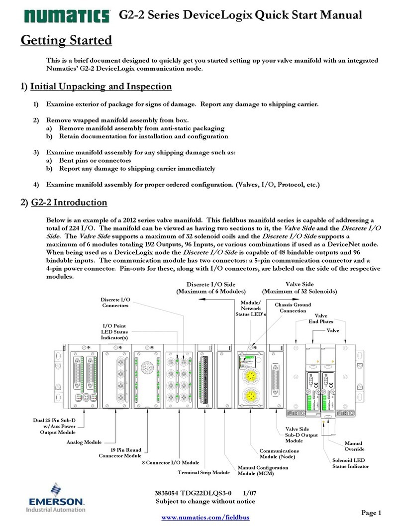
Emerson
Emerson Numatics DeviceLogix G2-2 Series Quick start manual
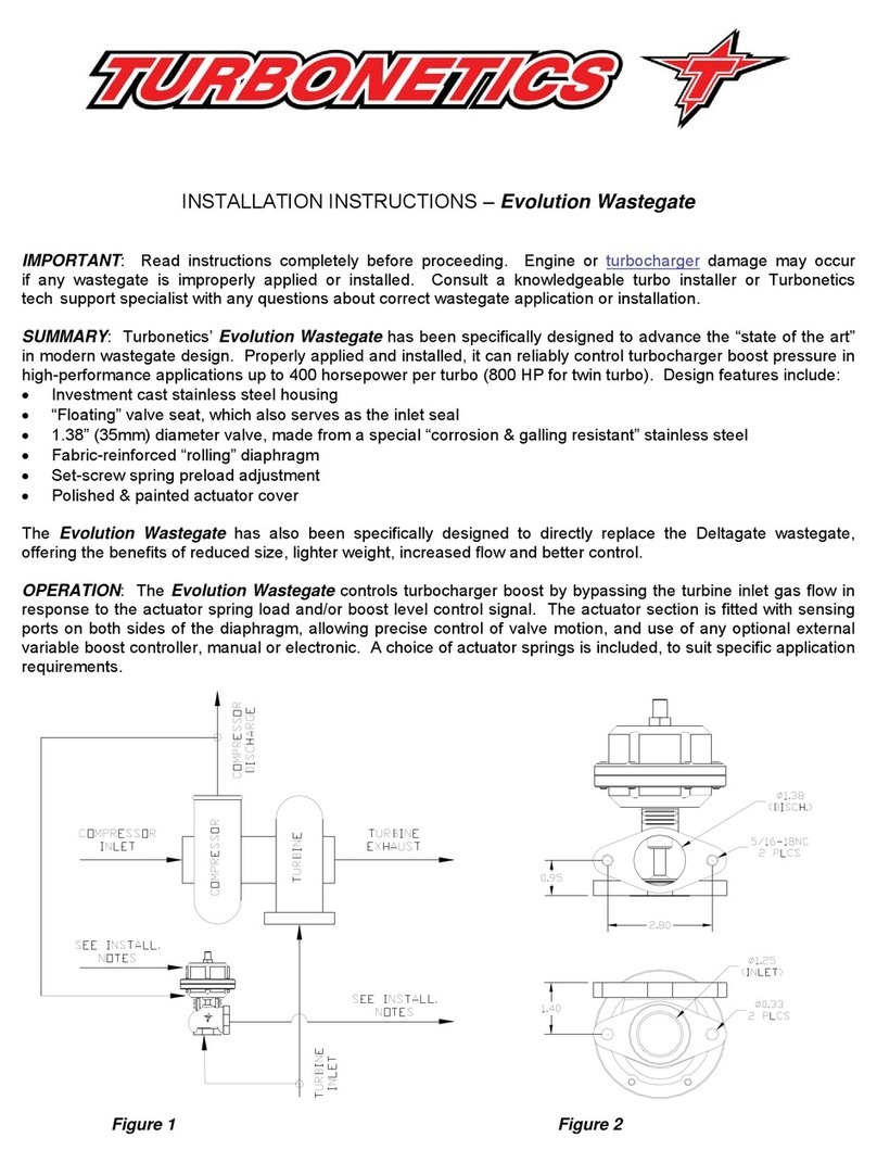
Turbonetics
Turbonetics Evolution Wastegate 10780 Installation instructions manual

Simplex
Simplex 2004 Series installation guide
SMA
SMA 1C4-313-001-001 Replacement manual

H3C
H3C MSR Router Comware 5 Series Guide

Festo
Festo CPX-E-1CI manual
