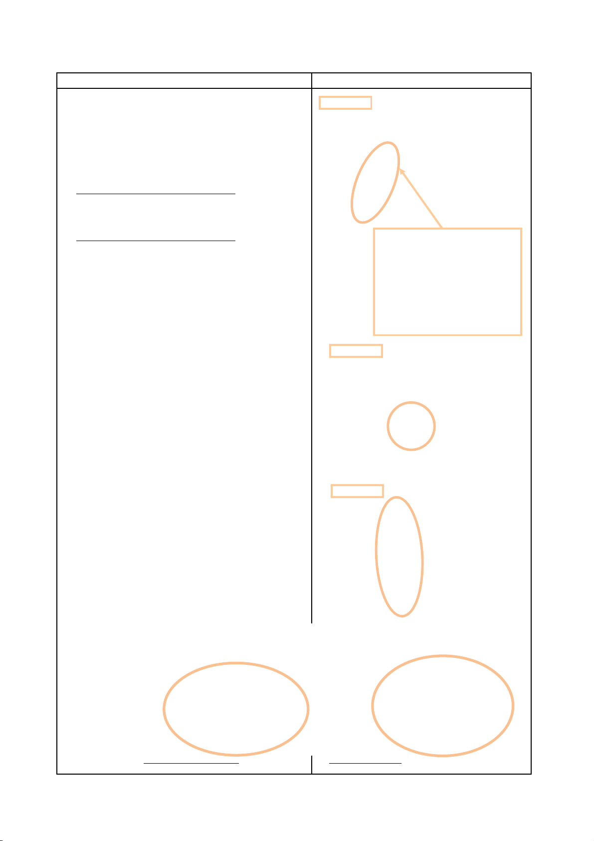
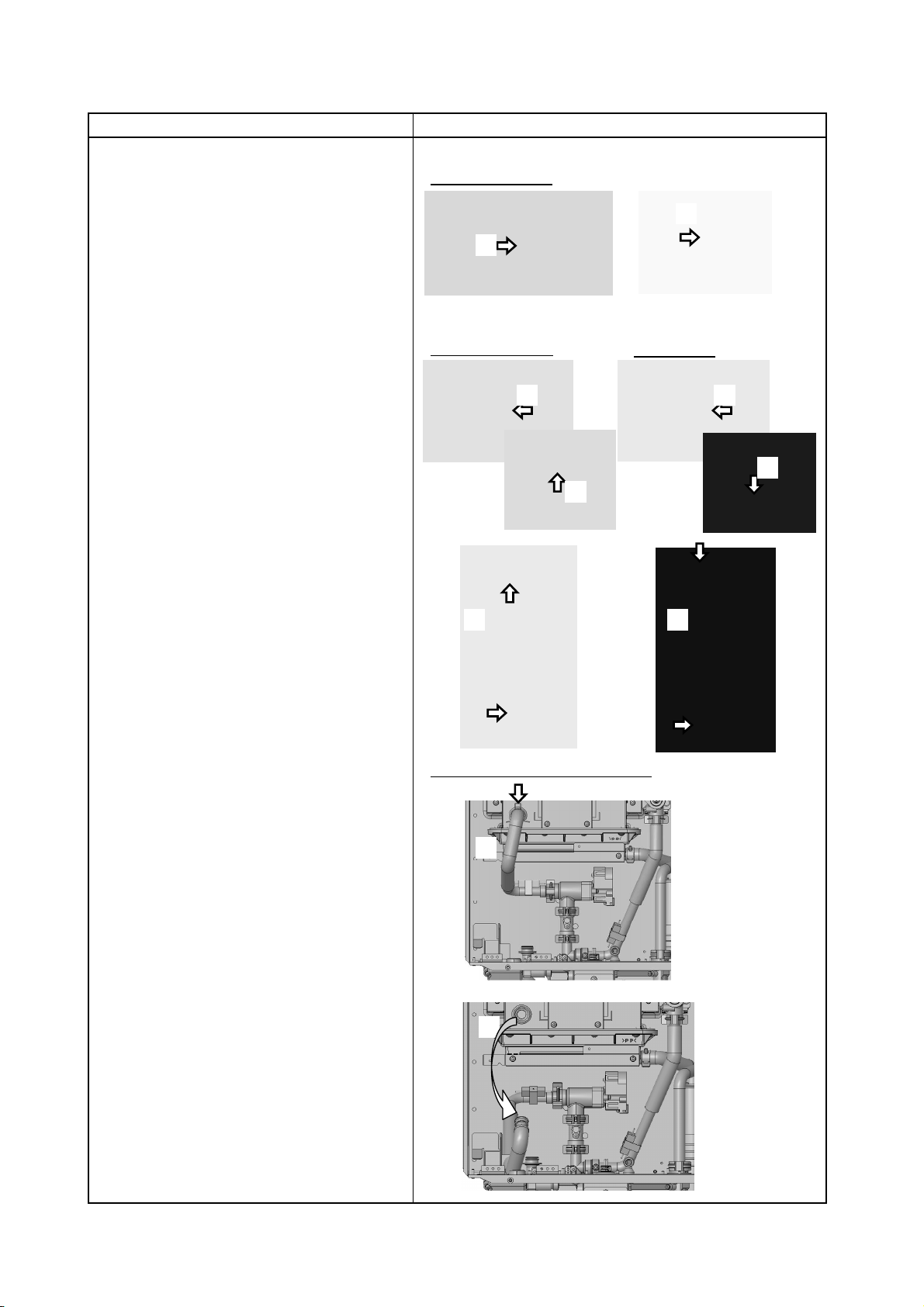
Heat Exchanger Replacement Procedure
Diagram
(5) Only EZ111DV/EZ98DV or NCC199CDV
Remove Cable Ties,
unplug 6 Freeze Prevention Heaters,
Water Servo - Bypass,
Gas Valve
Thermistor - Primary Heat Exchanger Inlet,
High Limit Switch. (EZ111DV/EZ98DV)
(NCC199CDV:2 High Limit Switches. )
(6) Unplug Igniter.
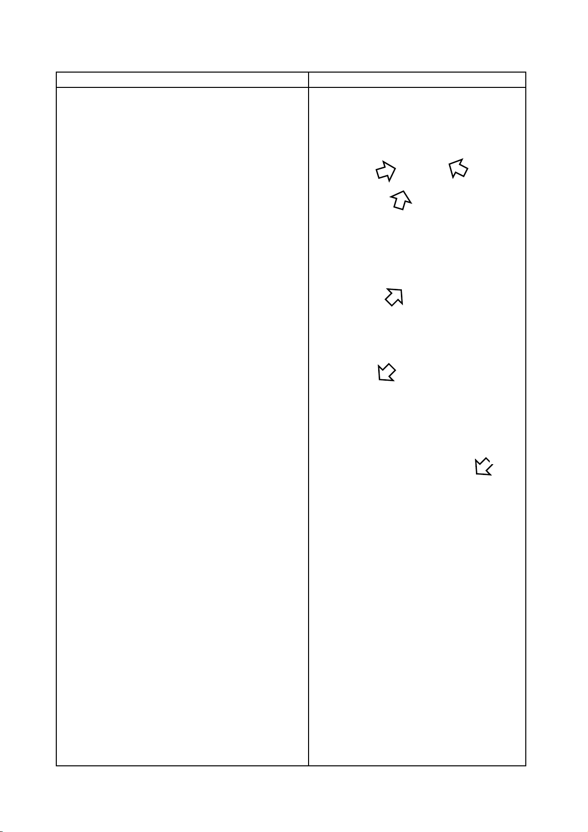
(7) For EZ111DV/EZ98DV or NCC199CDV
Detach the Wiring Harness from the clips.
Unplug 4 Freeze Prevention Heaters
(NCC199CDV:1 Freeze Prevention Heater. ),
Fan Motor,
Thermistor - Primary Heat Exchanger Outlet,
Thermistor - Exhaust.
For NRCB199DV/NRCB180DV
Detach Wiring Harness from Wire Clamps.
Unplug Fan Motor and Thermistor - Exhaust.
(8) Unplug High Limit Switch.
Page 6
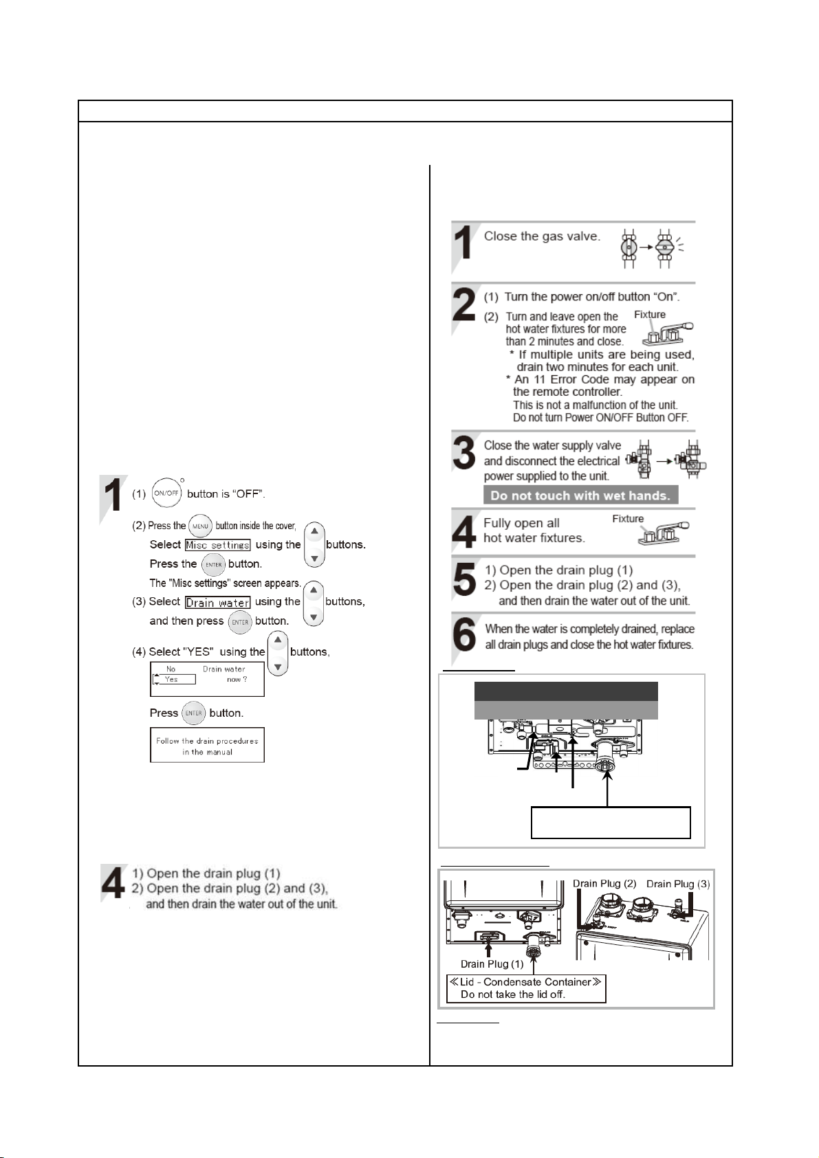
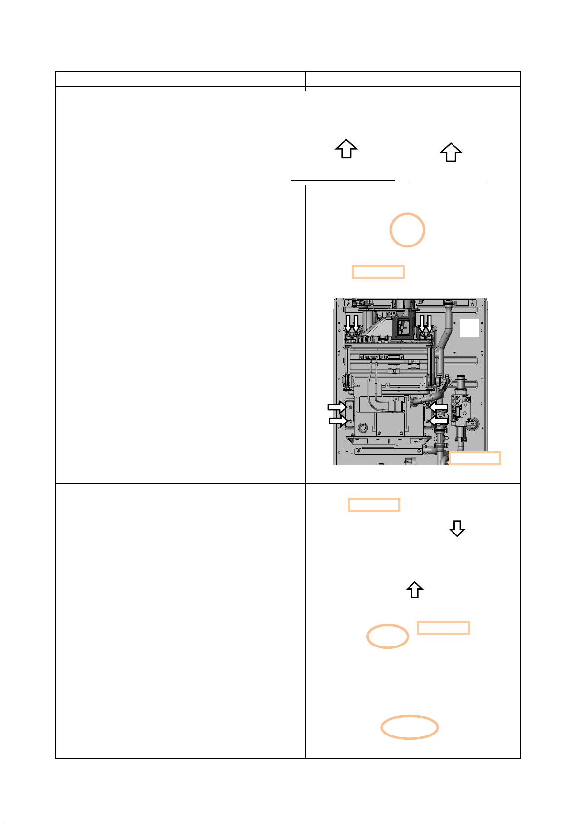
Procedure
EZ111DV/EZ98DV or NCC199CDV
Overall view
EZ111DV/EZ98DV NRCB199DV/NRCB180DV
(5)
(6)
EZ111DV/EZ98DV or NCC199CDV
NRCB199DV/NRCB180DV
(6)
NRCB199DV/NRCB180DV
NCC199CDV