Noritz N-0841MC User manual

N‐0841MC,N‐0842MC,NRC111andNCC199Series
HeatExchangerReplacement
ModelsInclude:N‐0841MC,N‐0841MC‐DV
N‐0842MC,N‐0842MC‐DV
NRC111‐SV,NRC111‐DV
NCC199‐SV,NCC199‐DV
ThisinstructionalmanualisonlyintendedforusebyaqualifiedserviceprofessionalorauthorizedNoritz
ServiceRepresentative.Anyunauthorizeduseofthismanualmayresultinvoidingthewarranty.
PleasecontactNoritzTechnicalSupport(866‐766‐7489)foradditionalsupport.
NoritzAmericaCorporation
11160GraceAvenue,FountainValley,CA92708
Phone866‐766‐7489Fax714‐241‐1196
Page 1

NRC111andNCC199(N‐0841MC,N0842MCSeries)HeatExchangerReplacementProcedure
ProcedureDiagram
1. Removefrontcover
(1) Disconnectelectricalpowertounit
(2) Remove4screws
(3) Turnoffgasandwater
(4) Removefilteranddrainunit
completely
(5) Opendrainportsonthebottomofthe
unit
2. RemoveGFCIandcircuitboard
(1) RemovetwoscrewsthatholdtheGFCI
Plate,onescrewwillhaveaground
wireattached),LetGFCIhangoutside
oftheunit
(2) Removethegroundwirethatistothe
leftofthecircuitboard
(3) Loosenwireanchorfromrightsideof
case
(4) Removethecircuitboard;thereare
twoscrews,oneontopandbottomof
thecircuitboard.Letthecircuitboard
hangoutsideoftheunit
Page 2

ProcedureDiagram
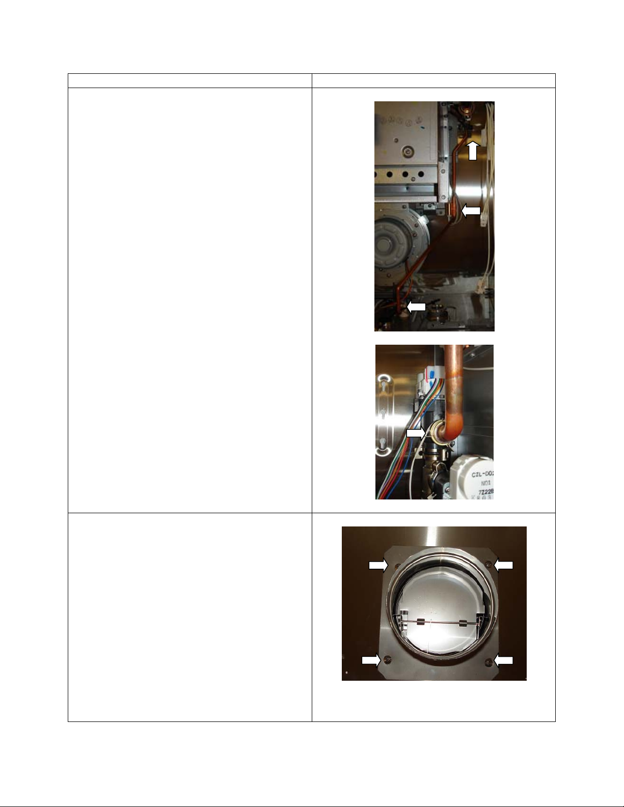
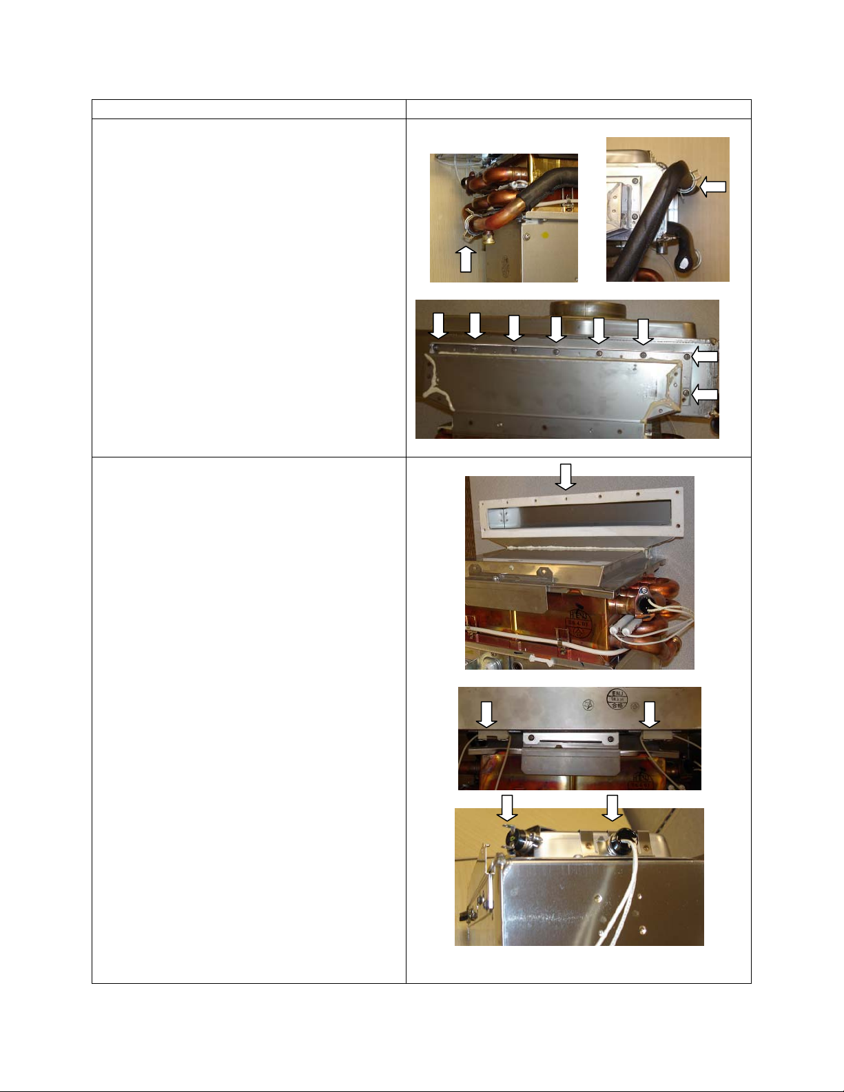
3. Removegasvalveassembly
(1) Locate“C”clamponthebottomright
handcorneroftheunitthatattaches
thegasconnectiontothemanifold
plateandremove.
(2) Locateinletgaspipetomanifoldand
pushup.
(3) Locatethelargewiringconnection,
thatattachesthewiresfromthe
manifoldplatetothewiringharness,
anddisconnecttheplug.
(4) Nextlocatethefourbigsilverscrews
holdingthemanifoldplatetothe
burner,therewillbetwoontheright
andleftsideofthemanifoldplate.
Removethosefourscrewsandthe
manifoldplateandpipecanbe
removedandsetaside.
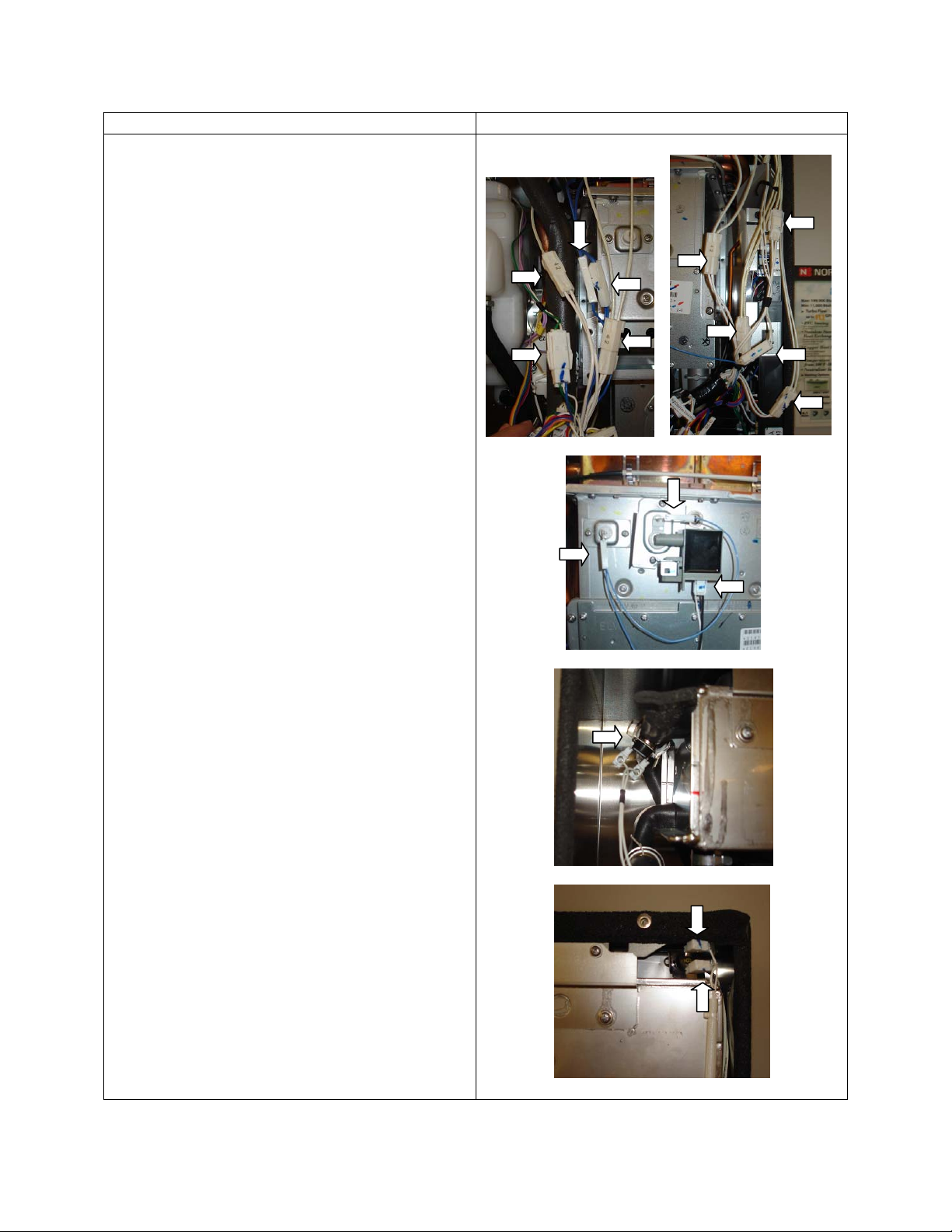
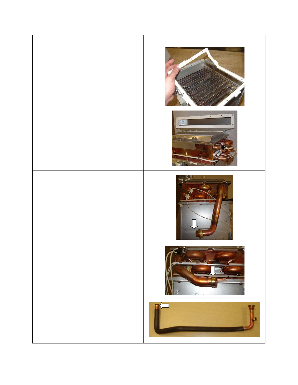
4. Unplugallwiresthatattachtothewiring
harnessandthebodyofthewaterheater
(1) Wiringforthefan
Page 3

ProcedureDiagram
(2) LeftSideWiringHarness:Thermalfuse
(2),Freezepreventionheaters(2),
Neutralizersensorplug
(3) RightSideWiringHarness:Highlimit
switch(2),Freezeprevention
heater(2),Freezepreventionsensor
(4) Flamerods(2),ignitionbox
(5) LeftSideOnStainlessSteelHeat
Exchanger(akaSSHE):Freeze
preventionsensor(takeoffwholeclip)
(6) RightSideOnSSHE:Freezeprevention
sensorplugs(2)
Page 4

ProcedureDiagram
5. RemovingtheNeutralizer
(1) Removethescrewholdingthemetal
clamponthetopofneutralizer
(2) Removethe3springclampsonthe
hosesoftheneutralizer.1willberight
belowtheSSHEand2willbeonthe
neutralizer(youwillneedaneedle
noseplierstoopenspringclamps)
(3) Pullhosesoffwhereclampswere
removed
(4) Liftuponneutralizerandpulloutand
setaside
6. RemoveWaterPipesInsideUnit
(1) Remove“C”Clampontopoffoam
coveredpipegoingintoSSHE
(2) Remove“C”Clamponbottomof
foamcoveredpipegoingintoFlow
Sensor
(3) RemovePipeandsetaside
Page 5

ProcedureDiagram
(4) Locate¼”drainpipeonrighthandside
ofunitanddisconnectbothsmall“C”
Clampsontopandbottomofpipe
(5) DisconnectFreezepreventionheater
on¼”drainpipe
(6) Remove¼”DrainPipeandsetaside
(7) LeftSide:Disconnect“C”Clampfrom
CopperHeatExchanger(akaCUHE)
andMainWaterControlValve
(8) Pulloutpipe
7. RemoveFluefromTopofUnit
(1) Disconnecttheventingfromtheunit
(2) Removethe4screwsandpulltheFlue
offoftheunitandsetaside
Page 6

ProcedureDiagram
8. Removeheatexchangerfromcase
(1) Removethe2setscrewsonthe
bottomoftheburner
(2) Removetheupperleftandrightset
screwsnearthetopcenterofthecase
(supportbottomofassembly)
(3) SSHE,CUHE,Burner,andFanwill
comeoutinonesection.Remove
fromunit.
9. SeparatetheSSHEfromCUHE
(1) Removethe2screwonthebracket
betweentheSSHEandCUHE
(2) FliptheAssemblyoverandlocatethe
foamcoveredpipeconnectingthetwo
heatexchangers
Page 7

ProcedureDiagram
(3) Removethe2“C”Clampsonthe
endofeachpipeandremovepipe
andsetaside
(4) Removethe9screwsthatlocated
onthebacksideoftheSSHE
(5) SeparatetheSSHEfromtheCUHE
10. ReplacingStainlessSteelHeat
Exchanger
Note:IfyouarenotreplacingtheSSHE
thenyoucanskipthisstepandsetSSHE
side.
shippedintheheatexchanger
theSSHEand
LimitSwitchandplaceonnewSSHE
a
(1) CheckthegasketontheCUHE,ifit
isdamagedreplaceitwithonethat
was
kit
(2) Removethe2FreezePrevention
Heateronthefrontof
placeonnewSSHE
(3) OnRightSideofSSHE,remove
FreezePreventionSensorandHigh
Page 8

ProcedureDiagram
11. ReplacingtheCopperHeatExchanger
(1) Remove12screwsholdingburner
toheatexchanger
(2) SeparateburnerfromCUHE
12. Removeheatexchangercomponents
andputonnewheatexchanger
(1) LeftSide:FreezePreventionHeater
(2) RightSide:HighLimitSwitch
(3) Thermalfuseandfastenersfrom
foursidesofheatexchanger
LEFTSIDE
BACK
RIGHTSIDE
FRONT
Page 9

ProcedureDiagram
13. Replacegaskets
(1) Removeoldburnergasketand
replacewithnewone
(2) InspectgasketbetweenSSHEand
CUHEExhaustBox,ifthegasketis
damaged,replaceit.
14. PlacenewO‐RingsonnewCUHEand
PipebetweenCUHEandSSHE
(1) InlettoCUHE
(2) ExittoCUHE
(3) FoamPipethatconnectsSSHEand
CUHE
Page 10

ProcedureDiagram
15. Reattachburner,CUHE,andSSHE
(1) 12screwsaroundperimeterof
burnerandheatexchanger
(2) TurnAssemblyaroundexposing
backsideoftheassembly
(3) Attach9screwstoholdtheSSHEto
theCUHE
(4) AttachtheFoamCoveredPipewith
the2“C”Clamp.Makesureto
insertpipeinallthewaybefore
attaching“C”Clamp.
(5) FlipAssemblyaroundexposing
Frontsideofassembly
(6) Attach2screwstoholdSSHEto
bracketonCUHE
Page 11

ProcedureDiagram
16. Replaceassemblybackinsidecase
(1) LocatehooksontopofSSHE(See
BlownUpView)
(2) Locatenotchesontopofwater
heatercase.
(3) Thehooksfromtheheatexchanger
willhelpalignandholdassemblyin
place
(4) Securebottomburnerscrews
(5) Securetopleftandrightscrews
Page 12

ProcedureDiagram
17. Reconnectwaterconnections
(1) InsertPipefromCUHEintoMain
WaterControlValveandattach“C”
Clamp
(2) InsertFoamCoveredPipeintothe
flowsensorandSSHEandattachwith
“C”Clamps
(3) Insert¼”DrainPipeintoCUHEand
DrainPortandattachwithsmall“C”
Clamps
(4) ReconnectFreezePreventionHeater
on¼”DrainPipeintothewiring
harness
18. Reinstallneutralizer
(1) Locatethe3keyholesinsidecase
(2) Locatethe3knobsontheneutralizer
(3) Lineuptheknobswiththekeyholes
andpulldowntosecureneutralizer
Page 13

ProcedureDiagram
(4) Attachwithascrewthemounting
platetosecuretheneutralizerto
bracketoncase
(5) Reattach3hoseswithclamps,youwill
needaneedlenosepeelersforthese
clamps
19. Replacegasvalveassembly
(1) Securegasvalveassemblytoburner
with4silverscrews
(2) Securemanifoldpipetogasinlet
fittingwith“C”clamp.
(3) Reconnectlargewiringconnection,
thatattachesthewiresfromthe
manifoldplatetothewiringharness
Page 14

ProcedureDiagram
20. Reconnectallwiresthatattachtothe
wiringharnessandthebodyofthewater
heater
(1) Wiringforthefan
(2) LeftSideWiringHarness:Thermalfuse
(2),Freezepreventionheaters(2),
Neutralizersensorplug
(3) RightSideWiringHarness:Highlimit
switch(2),Freezeprevention
heater(2),Freezepreventionsensor
(4) Flamerods(2),ignitionbox
(5) LeftSideOnSSHE:Freezeprevention
sensor(replaceclipwithwires
attached)
(6) RightSideOnSSHE:Freezeprevention
sensorplugs(2)
Page 15

ProcedureDiagram
21. ReplacecircuitboardandGFCI
(1) Slidecircuitboardbackintooriginal
position
(2) Securetopofcircuitboardscrew
(3) Securebottomofcircuitboardscrew
andgroundwiretotheleft
(4) SecureWireAnchorabovecircuit
board
(5) SecureGFCIplatetocasewith2
screws(groundwireonrightside)
Page 16

ProcedureDiagram
22. ReplaceFluefromTopofUnit
(1) Insetflueintopofunitandsecurethe
4screws
(2) Reconnecttheventingtotheunit
23. ReplaceFrontCover
(1) Replacewaterinletfilter
(2) CloseDrainPorts
(3) Turnoncoldwatershutoffvalve
slowly(checkforleaksaround“C”
clamps)
(4) Ifyougetleaksshutoffwaterandre‐
secure“C”Clamps.
(5) Turnongas(check“C”clampsfor
leaks)
(6) Securefrontcoverwith4screws
(7) Returnelectricalpowertotheunit
Page 17
Other manuals for N-0841MC
2
This manual suits for next models
11
Table of contents
Other Noritz Industrial Equipment manuals
Popular Industrial Equipment manuals by other brands

Colli FGB
Colli FGB BATTISTIRA user manual

Nibe
Nibe ERS 10-500 Installer manual

ABB
ABB CPS3200U product manual

RS Automation
RS Automation AnyTouch V7 Plus Series operating instructions

UNIFILLER
UNIFILLER Mini Dopositor Operation and Spare Parts Manual

flexfactory
flexfactory anyfeed SX Series Quick setup and user guide