NRC661SeriesHeatExchangerReplacementProcedure
Diagram
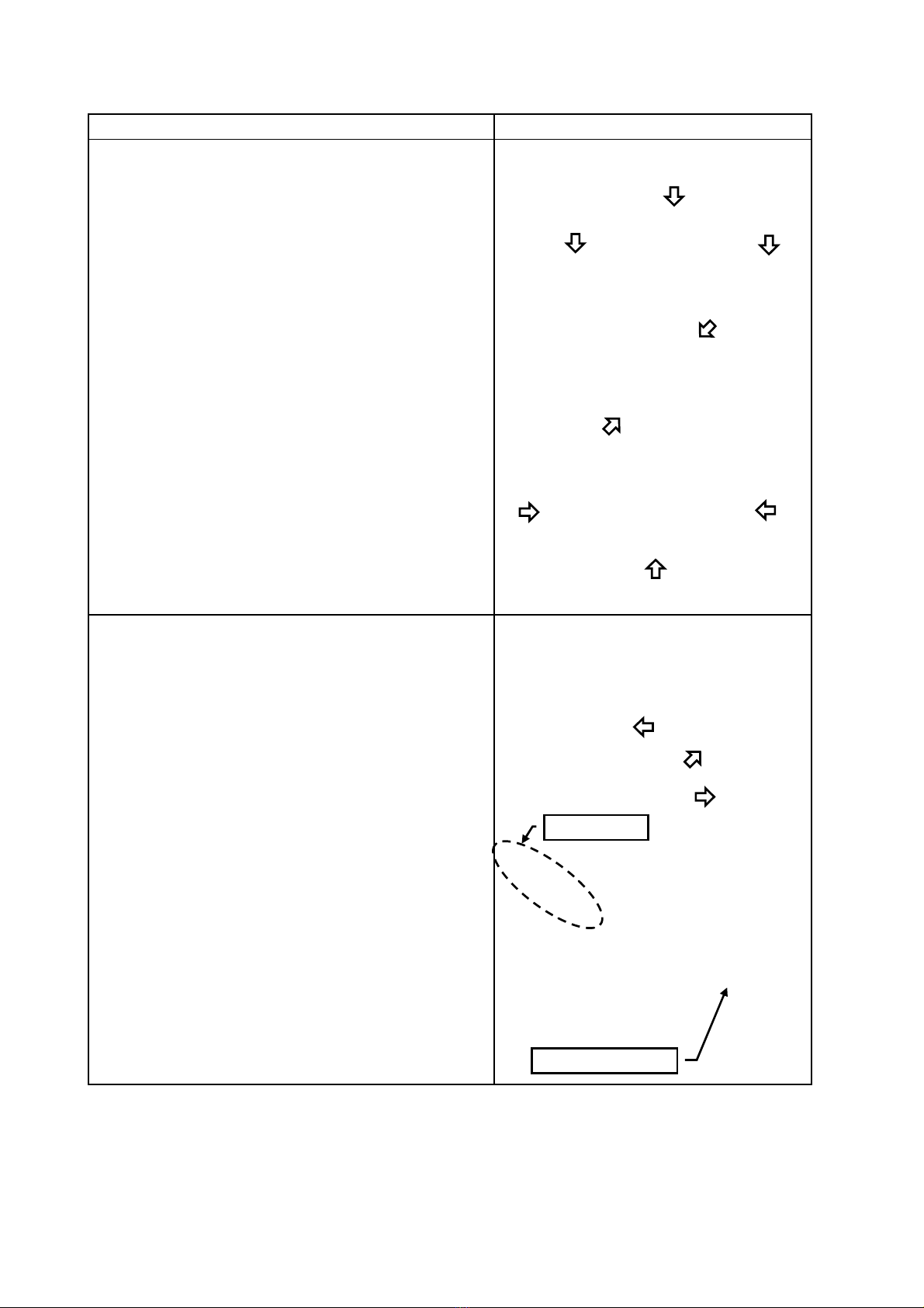
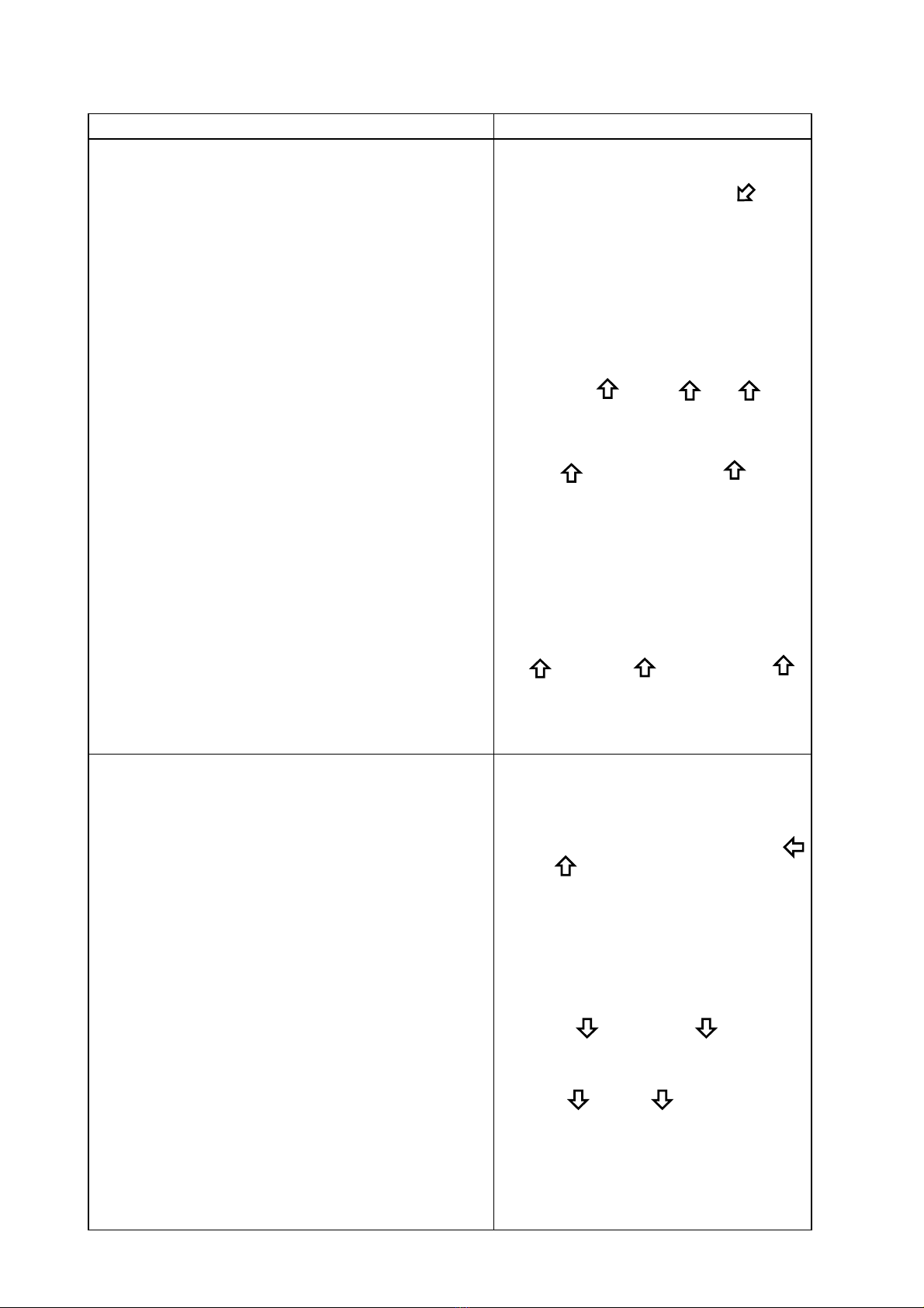
1.
(1) Disconnectelectricalpowertounit
(2) Turnoffgasandwater
(3) Remove4screws
(4) Removedrainvalves(2)anddrainunitcompletely
(5) Removecover‐circuitboard
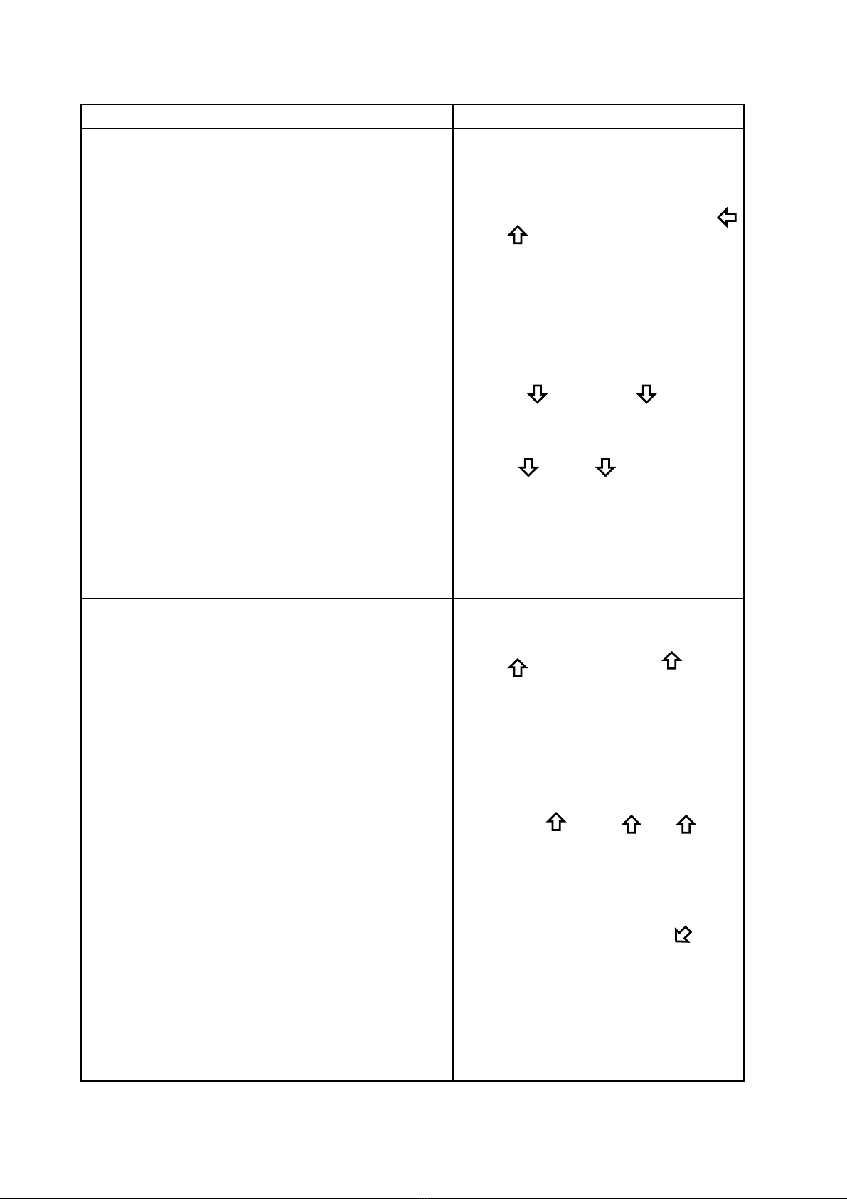
2.
(1) Disconnecttheconnectorsfromcircuitboard
(2) Removethegroundwire
DVmodel;3groundwires
ODmodel;2groundwires
(3) Removethecircuitboard;thereare2screws,oneon
theright‐sideandmiddle‐upperofthecircuitboard.
Letthecircuitboardhangoutsideoftheunit
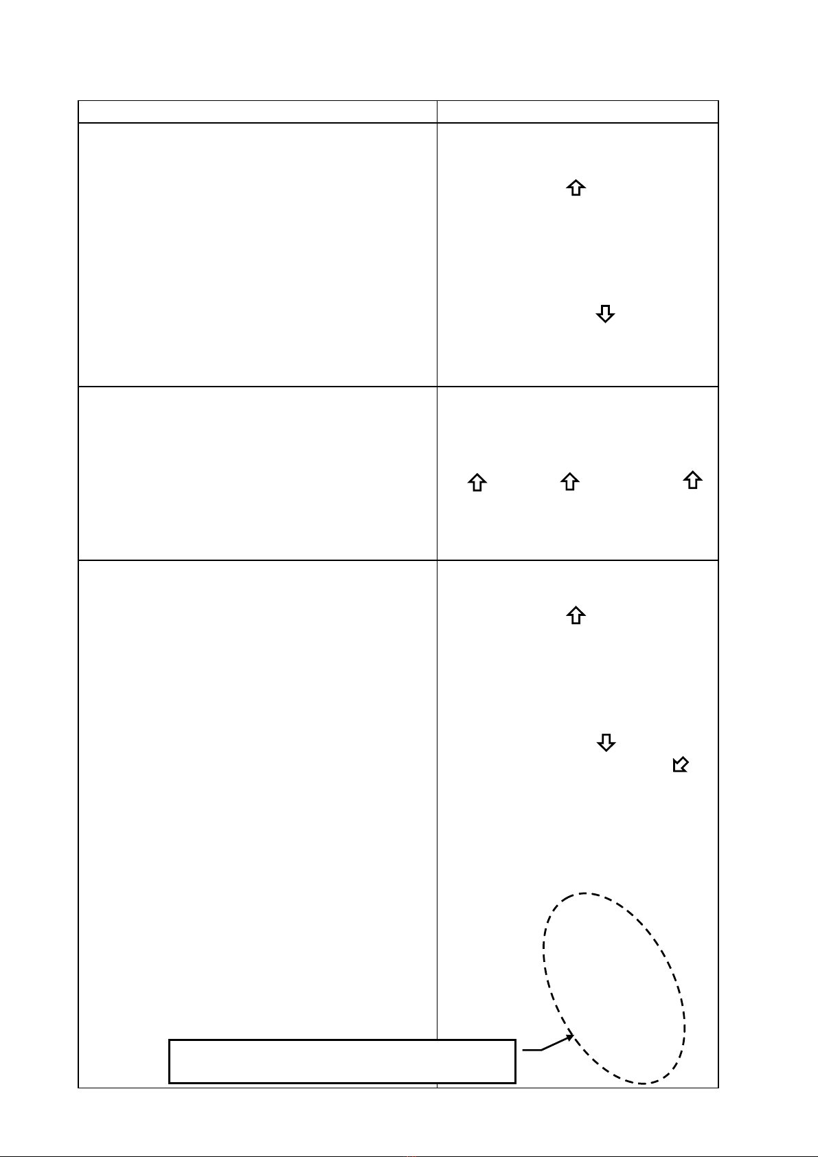
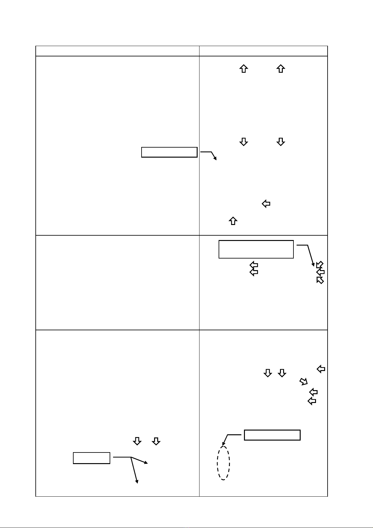
3.
(1) Flamerodandignitionplug
(2) Loosenwireanchorfromrightsideofcaseandunplug
freezepreventionheater,thermalfuse(2)
(3) Unplugallwiresthatattachtothewiringharness
exceptwaterservo‐main
(4) *DVmodelonly
Unplugfreeze
preventionheater,
thermistor
‐exhaust.
Releasethewire
clamps
Page2
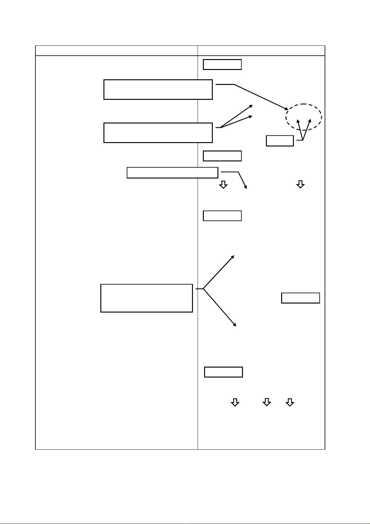
Unplugallwiresthatattachtothewiringharnessandthe
bodyofthewaterheater
Procedure
Removefrontcover
Disconnecttheconnectorsfromcircuitboardandremovethe
groundwire,circuitboard ODmodelhasonlyascrew
oftheupperside
WaterServo‐Main
3
1
2
Cover‐CircuitBoard
4
Wireclamp