3
IMPORTANT SAFETY INFORMATION
INSTALLER: Please read all instructions before servicing
this equipment. Pay attention to all safety warnings and
any other special NOTES highlighted in the manual.
Safety markings are used frequently throughout this
manual to designate a degree or level of seriousness and
should not be ignored. WARNING indicates a potentially
hazardous situation that if not avoided, could result in
personal injury or death. CAUTION indicates a potentially
hazardous situation that if not avoided, may result in minor
or moderate injury or property damage.
• This appliance is not intended for use by persons
(including children) with reduced physical, sensory
or mental capabilities, or lack of experience and
knowledge, unless they have been given supervision
or instruction concerning use of the appliance by a
person responsible for their safety.
• Children should be supervised to ensure that they do
not play with the appliance.
WARNING:
ELECTRICAL SHOCK, FIRE OR
EXPLOSION HAZARD
Failure to follow safety warnings exactly
could result in serious injury, death or
property damage.
Improper servicing could result in dangerous
operation, serious injury, death or property
damage.
• Before servicing, disconnect all electrical
power to the unit.
• When servicing controls, label all wires
prior to disconnecting. Reconnect wires
correctly.
• Verify proper operation after servicing.
WARNING:
Unless noted otherwise in these instructions,
only factory authorized parts or accessory
kits may be used with this product.
Improper installation, service, adjustment,
or maintenance may cause explosion,
fire, electrical shock or other hazardous
conditions which may result in personal
injury or property damage.
• Use caution when removing components or handling
this product. Personal injury can occur from sharp
metal edges present in all sheet metal constructed
equipment.
ELECTRICAL SUPPLY
• If the unit was previously installed without electric heat,
the existing supply wiring may not be sufficient to handle
the increased load. See the unit rating label or
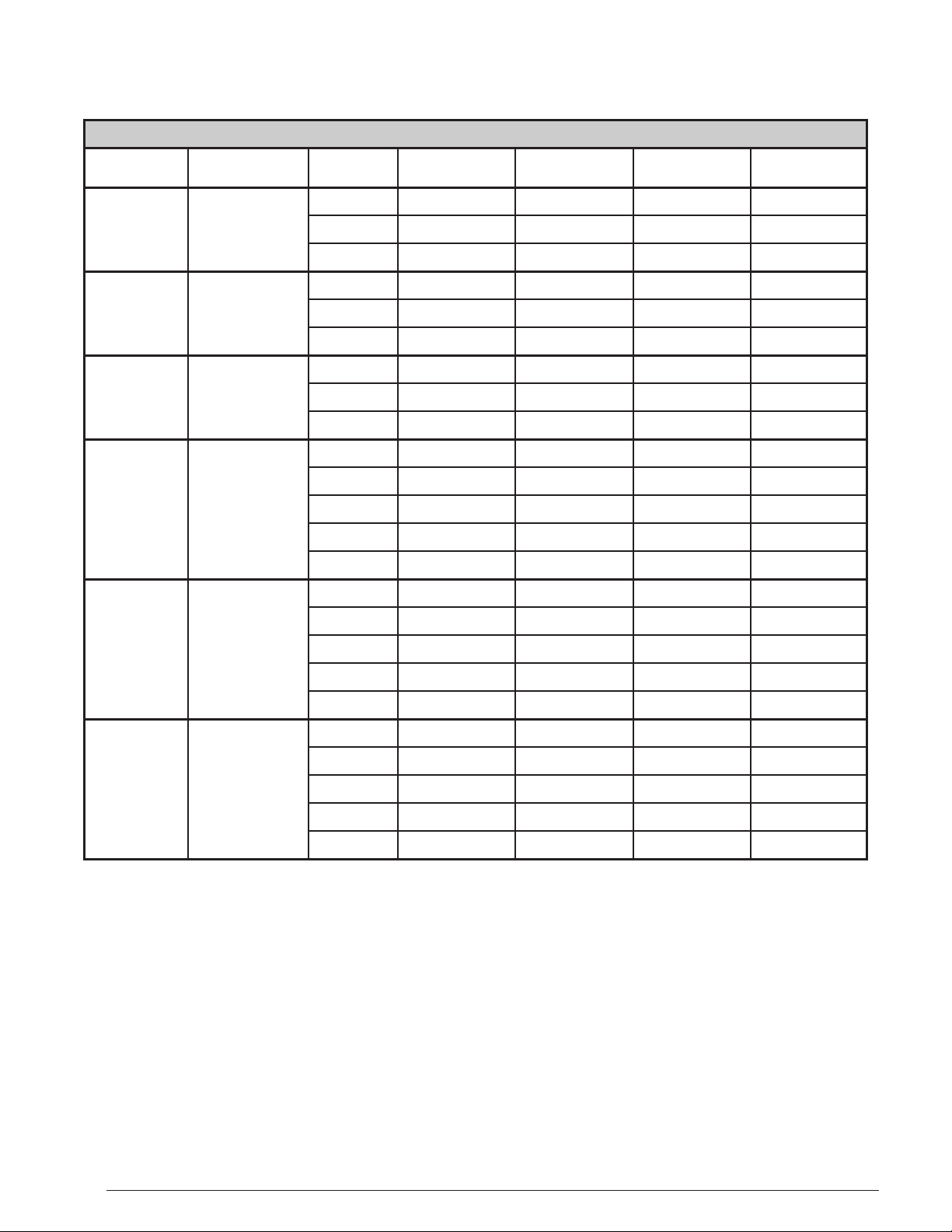
Table 8 (page 11), Table 9 (page 12) and Table 10 (page 13)
for minimum circuit ampacities and maximum overcurrent
protection ratings.
• Units with installed electric heat may be supplied by a single
circuit or by multiple circuits. Additional accessory kits
may be required if single circuit installation and/or circuit
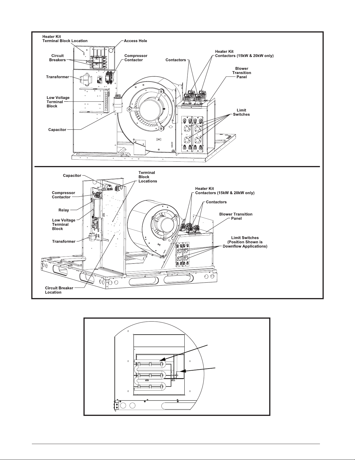
breakers are desired. See Figure 1 for kit identification
and Table 1 for part numbers and accessory descriptions.
Circuit Options
The units with electric heat may be wired for single or
multiple circuits and may have circuit breakers or terminal
blocks. NOTE: Circuit breakers installed in the unit are
for short- circuit protection of the internal wiring and to
serve as a unit disconnect. The circuit breakers DO NOT
provide overcurrent protection of the supply wiring.
• Overcurrent protection must be provided at the branch
circuit distribution panel even if circuit breakers are not
used in the units. It must be sized as shown in
Table 8 (page 11), Table 9 (page 12) and Table 10
(page 13) or on the unit rating label and according to
the National Electric Code, Canadian Electrical Code
and applicable local codes. NOTE: In most cases the
overcurrent protection specified on the unit rating label
is less than the 60 amp rating of the circuit breakers
used in the units. This is because the function of the
overcurrent protection required at the distribution
panel (field supplied) and the unit mounted breakers
is different.
• When circuit breakers are used they must be used on
all circuits. Refer to Table 5 (page 8), Table 6 (page 9)
and Table 7 (page 10) for the correct circuit breaker for
the application.
• If the number of circuits listed in Table 5 (page 8),
Table 6 (page 9) and Table 7 (page 10) are more than
1, circuit breakers are required. If single circuit supply
wiring is desired: Use the 4-pole circuit adapter kit (P/N
GENERAL INFORMATION
H3HK heater kits are approved for use in packaged air
conditioners and packaged heat pumps when applied
and installed according to these instructions. See
Table 5 (page 8), Table 6 (page 9) and Table 7
(page 10) for approved H3HK air conditioner and heat
pump applications. Refer to the National Electric Code
(ANSI/NFPA 70) or in Canada the Canadian Electric
Code Part 1 (CSA C.22.1) and applicable local codes
for overcurrent protection and disconnect requirements.
Clearances to Combustibles
All units are approved for zero clearance to combustibles
when installed according to these instructions and other
instructions included with the unit and other approved
accessories. See Table 1, (page 4).