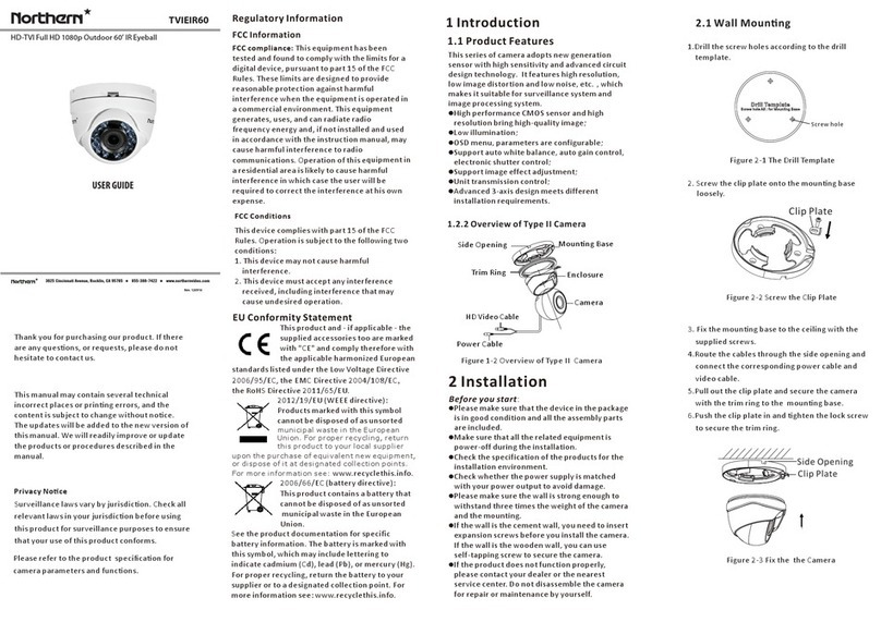
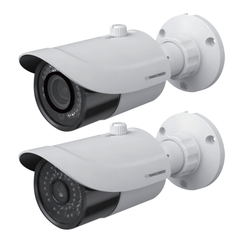
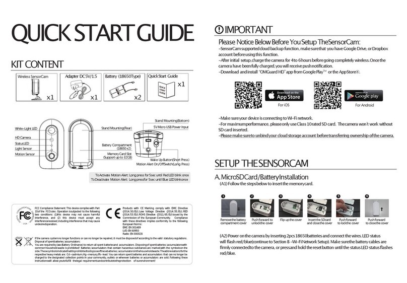
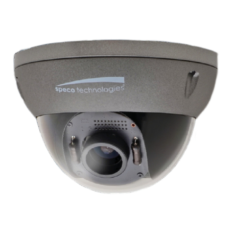
NOTHERN TVIMDIR120 Assembly instructions

TVIMDIR120
HD-TVI Full HD 1080p Varifocal 120’ IR Dome w/ Motorized Lens
Rev. 102115
3625 Cincinnati Avenue, Rocklin, CA 95765
i
855-388-7422
i
www.northernvideo.com
Installation & Quick Setup Guide
Regulatory Informaon
FC C Informaon
FCC compliance:This equipment has been
tested and found to comply with the limits for a
digital device, pursuant to part 15 of the FCC
Rules. These limits are designed to provide
reasonable protecon against harmful
interference when the equipment is operated in
a commercial environment. This equipment
generates, uses, and can radiate radio
frequency energy and, if not installed and used
in accordance with the instrucon manual, may
cause harmful interference to radio
communicaons. Operaon of this equipment in
a residenal area is likely to cause harmful
interference in which case the user will be
required to correct the interference at his own
expense.
FCC Condions
This device complies with part 15 of the FCC
Rules. Operaon is subject to the following two
condions:
1. This device may not cause harmful
interference.
2. This device must accept any interference
received, including interference that may
cause undesired operaon.
EU Conformity Statement
upon the purchase of equivalent new equipment,
or dispose of it at designated collection points.
For more information see:www.recyclethis.info.
2006/66/EC (baery direcve):
This product contains a baery that
cannot be disposed of as unsorted
municipal waste in the European
Union.
See the product documentaon for specific
baery informaon. The baery is marked with
this symbol, which may include leering to
indicate cadmium (Cd), lead (Pb), or mercury (Hg).
2012/19/EU (WEEEdirecve):
Products marked with this symbol
cannot be disposed of as unsorted
municipal waste in the European
Union. For proper recycling, return
this product to your local supplier
This product and - if applicable - the
supplied accessories too are marked
with "CE" and comply therefore with
the applicable harmonized European
standards listed under the Low Voltage Direcve
2006/95/EC, theEMCDirecve 2004/108/E C ,
the RoH S Direcve 2011/65/EU.
1.2 Camera Overview
1 Introducon
1.1 Product Features
This camera adopts new generaon sensor with
high sensivity and advanced circuit board design
technology. It possessesthe features of high
resoluon, low distoron, and low noise, etc. It is
extremely suitable for supervisory system and
image processing system.
The main features are as follows:
Please make sure that the device in the package
is in good condion and all the assembly parts
are included.
Make sure that all the related equipment is
power-offduring the installaon.
Check the specificaon of the products for the
installaon environment.
Check whether the power supply is matched
with your power output to avoid damage.
Please make sure the wall is strong enough to
withstand three mes the weight of the camera
and the mounng.
If the wall is the cement wall, you need to insert
expansion screws before you install the camera.
If the wall is the wooden wall, you can use
self-tapping screw to secure the camera.
If the product does not funcon properly,
please contact your dealer or the nearest
service center. Do not disassemble the camera
for repair or maintenance by yourself.
For proper recycling, return the baery to your
supplier or to a designated collecon point. For
more informaon see: www.recyclethis.info.
2 Installaon
Before youstart:
Figure 1-1 Camera Overview
Lens
Black Liner
Bubble
DIP Switch
Auxiliary Video Output
Base Plate
Menu Joysck
2.1 Ceiling Mounng
Steps:
1.Drill the screw holes and the cable hole on the
ceiling according to the supplied drill template.
Figure 2-1 The Drill Template
2Loosen the screws on the bubble of type 1
.
camera /rotate the bubble of type2 camera to
remove the bubble and the black liner.
Figure 2-2 Remove the Bubble
3.Aach the back box of type 1 camera /base plate
of type2 camera to the ceiling and secure them
with supplied self-tapping screws.
4.Route the cables through the cable hole.
High performanceCMOSsensor and high
resoluon bring high-quality image;
Turbo HD output, up to 1080P resoluon;
2.8 – 12mm motorized vari-focal lens;
OS D menu, parameters are configurable;
Support Day/Night switch;
SMART IR mode;
Support UTC funcon;
Built-in heater.
The built-in heater funcon varies according to
different models.
Thank you for purchasing our product. If there
are any quesons, or requests, please do not
hesitate to contact us.
This manual may contain several technical
incorrect places or prinng errors, and the
content is subject to change without noce.
The updates will be added to the new version of
this manual. We will readily improve or update
the products or procedures described in the
manual.
Privacy Noce
Surveillance laws vary by jurisdicon. Check all
relevant laws in your jurisdicon before using
this product for surveillance purposes to ensure
that your use of this product conforms.
Please refer to the product specificaon for
camera parameters and funcons.
HD
Video Cable
Power Cable
960H Video Cable

3 Menu Operaon
Figure 3-1 Main Menu
DAY&NIGHT
BACKLIGHT
INDOOR
OUTDOOR
INDOOR1
LOW-
LIGHT
MANUAL SHUTTER
AGC
SENS-UP
BRIGHTNESS
D-WDR
DEFOG
BLC
HSBLC
ATW
AWC-SET
MANUAL
COLOR
B/W
EXT
2D NR
3D NR
CAM
TITLE
D-EFFECT
MOTION
PRIVACY
LAUGUAGE
DEFECT
VERSION
SHARPNESS
MONITOR
LSC
VIDEO.
OUT SETUP
SMART
FOCUS
You can call the menu and adjust the camera
parameters with a coaxial camera controller
(purchase separately). You can also call the menu
with supported TVI DVR.
3.1 VI DEO.OUT
PAL or NTS C is selectable .
3.2LANGUAGE
English, Japanese,CHN1, CHN2, Korean, German,
French, Italian, Spanish, Polish, etc., are selectable.
3.3 SETUP
3.3.2 SCENE
You can select indoor, outdoor, indoor 1 and low
-light as the working environments.
3.3.3LENS
The camera is equipped with 2.8-12mm motorized
vari-focal lens.
3.3.4EXPOSURE
EXPOSURE
1. SHUTTER AUTO
2. AGC OFF
3. SENS-UP ---
4. BRIGHTNESS---|------ 40
5. DEFOG OFF
6. D-WDR OFF
7. RETURN RET
Figure 3-2 Exposure
SHUTTER: AUTO,1/25, 1/50, F LK, 1/200, 1/400,
1/1k, 1/2k, 1/5k, 1/10k, 1/50k, x2, x4, x6, x8, x10,
and x15 are selectable.
: You can set the AG C value from 0 to 15.AGC
: You can set the S ENS-UP to OFF or AUTO.SENS-UP
: You can set the brightness valueBRIGHTNESS
from 1 to 100.
: You can set the defog funcon as O N toDEFOG
enable the funcon. Posion, size, and the defog
gradaon are configurable.
You can set the D-WDR as ON or O FF.D-WDR:
3.3.5 Backlight
Backlight Compensaon (BLC):
Set the gain of BLC as High, Middle, or Low.-GAIN:
Press the up/down/le/right buon to-AREA:
define the B LC posion and size. SelectRET or
AGAIN to go back the BLC menu or re-define the
BLC area.
Restore the BLC sengs to the default.-Default:
HSBLC: Select an HS B LC area. Set theDISPLAY
status as ON. Press the up/down/le/right buon
to define the area posion and size. Set the H SBLC
LEVEL from 0 to 100. Select ALL DAY or Night for the
HS BLC mode. Set theBLACK M ASK status as O N or
OFF.
HSBLC
1. SELECT AREA 1
2. DISPLAY ON
3. LEVEL ---|------ 40
4. MODEALLDAY
5. BLACK MASK ON
6. DEFAULT
7. RETURNRET
Figure 3-3 H SBLC
3.3.6 White Balance (W B)
MANUAL , ATW (Auto-tracking White Balance),
AWC→SET are selectable.
3.3.7 Day & Night
Color, B/W, andEXT are selectable for DAY and
NIGHT switches.
3.3.8 NR
: You can set 2D NR status as ON or O FF.2D NR
: Set the Smart N R status as ON and adjust3D NR
the 3D smart N R sensivity ranges from 0 to 100.
Set the 3D NR LEVEL ranges from 0 to 100. Set the
2D&3D NR
1. 2DNR OFF
2. 3DNR ON
3. RETURN RET
3D NR
1. SMART NR ON
2. LEVEL ------|--8 0
3. START. AGC -|--------10
4. END. AGC -|--------10
5. RETURN RET
Figure 3-4 N R
Figure 3-5 3D NR
3.3.9 SP EC IAL
Edit the camera tle on this secon.Camera Title:
D-effect:
Set the freeze funcon as O N or OFF.-FREEZE:
OFF, MIRRO R, V-FLIP, and ROTATE are-MIR ROR:
selectable for mirror.
Define the zoom area by configuring-D-ZOOM:
the posion from PAN&TILT.
The D-Zoom area, sensivity-SMART D-ZOOM:
and me are configurable.
Set the N EG IMAGE as ON or OFF.-NEG.IM AGE:
SPECIAL
1. CAM TITLE ON
2. D-DFFECT
3. MOTION OFF
4. PRIVACY OFF
5. DEFECT
6. RETURN RET
Figure 3-6 Special
MOTION
1. SELECT AREA 1
2. DISPLAY ON
3. SENSITIVITY ----|---- 30
4. MOTION VIEW ON
5. DEFAULT
6. RETURN RET
Figure 3-7 Moon Detecon
Moon: Select a MOTION area. Set theDISPLAY
status as ON or O FF. Press the up/down/le/right
buon to define the posion and size of the area.
Set the S ENSITIVITY from 0 to 60. Set the MOTION
VIEW status as ON or OFF.
Privacy: Select a PRIVACY area. Set theDISPLAY
status as INV, MOSAIC, CO LO R or OFF. Press the
up/down/le/right buon to define the posion
and size of the area.
Defect:LIVEDPC, STATICDPCand BlackDPC are
adjustable in this secon.
PRIVACY
1. SELECT AREA 1
2. DISPLAY MOSAIC
3. COLOR 10
4. TRANS. 1
5. DEFAULT
6. RETURNRET
ADJUST
1. SHARPNESS --------|15
2. MONITOR LCD
3. LSC OFF
4. RETURNRET
3.3.10 ADJUST
: Adjust the sharpness from 0 to 15.Sharpness
: Monitor CRT, and Monitor LC D areMonitor
selectable.
: Set the L SC status as O N or OFF.LSC
3.3.11 RESET
Reset all the sengs to the default.
3.3.12EXIT
Press O K to exit the menu.
STA RT. AG C level as the threshold to enable A GC,
and set the E ND. AG C level as the threshold to
disable AGC.
Figure 3-8 Privacy MaskFigure 3-9 Adjust
3.3.1 SMART FOCU S
Move the joysck to adjust the camera lens by the
FOCUS+, FOCUS-, ZOOM+ and ZOOM-. The smart
focus value turns higher when the focusing
effecveness turns beer. The value range is 0~99.
Steps:
1.Drill the screw holes and the cable hole in the
ceiling according to the supplied drill template.
2.Screw the bolts through the mount by aligning
with the 2 bolt holes. Fit the toggles onto the bolts.
3.Push the two toggle bolts through the two screw
holes on the ceiling. Rotate the bolt ll the toggle
holds the ceiling ghtly.
2.2 In-ceiling Mounng
Figure 2-5 Install the Mount
4.Route and connect the corresponding cables.
5.Fix the camera to the in-ceiling mount with the
supplied screws.
Figure 2-3 Fix the Camera to the Ceiling
6. Connect the corresponding cables.
7. Adjust the camera according to the figure below
to get an opmum angle.
8. Fit the black liner on the camera and ghten the
screws on the bubble of type 1 camera or rotate the
bubble of type 2 camera to complete.
Figure 2-4 3-axis Adjustment
You need to purchase an in-ceiling mount separately
if you adopt in-celling mounng.
P Direction
R Direction
T Direction
5.Align the camera with the back box/base plate,
and ghten the set screws to secure the camera
with the back box/base plate.
Figure 2-6 Fix the Camera to the Mount
Figure 2-8 Fix the Camera to the Gang Box
6. Repeat steps 6-8 of the Ceiling Mounng secon
to complete the installaon.
2.3 In-ceiling Mounng with
Gang Box
Only the type 1 camera supports in-ceiling
mounng with gang box.
1.Repeat steps 2-4 of the In-ceiling Mounng
secon to secure the in-ceiling mount (supplied)
to the gang box.
Figure 2-7 Install the Mount
2.Route and connect the corresponding cables.
3.Align the camera with the gang box, and ghten
the screws to secure the camera with the gang box..
4. Repeat steps 6-8 of the Ceiling Mounng secon
to complete the installaon.
0° ~75°
0° ~355°
0° ~355°
Other NOTHERN Security Camera manuals
