Novra S300N User manual

Version: 1.2
Confidential and Proprietary 1of 40
Novra S300N Receiver
User Manual
Subject to change without notification
CAUTION: Any changes or modifications not expressly approved by the manufacturer could
void the user's authority to operate this equipment.

Version: 1.2 Confidential and Proprietary 2of 40
Novra S300N
DVB-S2 Satellite Data Receiver
User Manual
Subject to change without notification
Document version: 1.2
________________________________
Important- Please read this entire manual before installing or operating this product.
________________________________
Disclaimer
While reasonable effort has been made in the preparation of this document to assure its accuracy, Novra
Technologies Inc. assumes no responsibility for errors or omissions that may appear in this manual. Novra
reserves the right to change the contents of this manual at any time without notice.
Copyright
© 2012 Novra Technologies Inc. All rights reserved.
Information in this manual is subject to change without notice. No part of this manual may be reproduced or
transmitted in any form without the express written permission of Novra Technologies Inc.

Version: 1.2 Confidential and Proprietary 3of 40
INDEX Page
1Conventions .................................................................................................................................. 4
1.1Text Conventions.................................................................................................................. 4
1.2Applicable Models................................................................................................................ 4
1.3Model Naming Convention................................................................................................... 5
2Introduction................................................................................................................................... 6
2.1Principles of Operation......................................................................................................... 6
3Getting Started.............................................................................................................................. 7
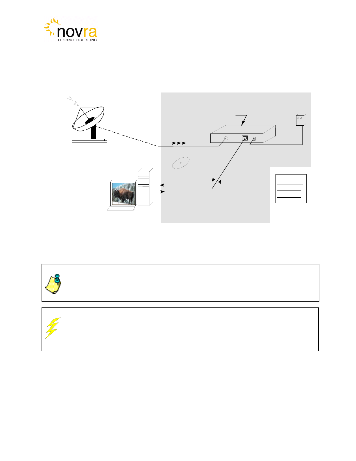
3.1Typical S300 Installation...................................................................................................... 7
3.2What Information do I Need – Basic Configuration?........................................................... 8
3.3SOFTWARE Installation on Windows 7.............................................................................. 9
3.4S300 Startup........................................................................................................................ 10
3.5Main Screen........................................................................................................................ 13
4Configuring the S300.................................................................................................................. 18
4.1Interfaces............................................................................................................................. 18
4.1.1Network Button............................................................................................................... 18
4.1.2Satellite Button................................................................................................................ 19
4.2IP Data ................................................................................................................................ 24
4.2.1Content Button................................................................................................................ 24
4.2.2IP Re-Mapping Button.................................................................................................... 25
4.3Control ................................................................................................................................ 28
4.3.1Reboot Button................................................................................................................. 28
4.4File Drop Down .................................................................................................................. 28
4.5Control Drop Down ............................................................................................................ 31
4.6Help Drop Down................................................................................................................. 32
4.6.1Help................................................................................................................................. 32
4.6.2About............................................................................................................................... 32
5Troubleshooting.......................................................................................................................... 33
6Specifications.............................................................................................................................. 35
6.1Receiver Characteristics...................................................................................................... 35
7Industry Canada Compliance Declaration.................................................................................. 37
8Minimum System Requirements................................................................................................. 37
9Supplied Equipment.................................................................................................................... 37
APPENDIX Terms, Definitions, and Tidbits of Information……………………………….....38

Version: 1.2 Confidential and Proprietary 4of 40
1 Conventions
1.1 Text Conventions
Text appearing in Courier font indicates characters to be typed in; e.g. type Shell indicates that
the word “Shell” must be entered exactly as it appears, with the first letter capitalized.
Text appearing in Bookman Old Style font indicates a directory path or filename; e.g. c:\Program
Files.
Text appearing in SMALL CAPS and CopperPlateGothic32bc font in an instruction indicates a button
that must be clicked, or a key that must be pressed, or a field that must be entered or a particular
screen; e.g. BUTTON indicates a button that must be clicked.
1.2 Applicable Models
This manual is applicable to the following Novra Receiver models:
Novra S300N – Enhanced DVB-S2/DVB-S satellite data receiver capable of receiving IP data,
NOTE: Information in this box
will be Informative.
CAUTION: This information
will be quite important and
should not be i
g
nored.
NOTE: - Your Novra S300 Configuration Application may also be used to configure other
Novra receiver families such as the S75 and the S200. This manual does not specifically
cover the configuration of these receivers, although the commands are very similar.

Version: 1.2 Confidential and Proprietary 5of 40
1.3 Model Naming Convention
This manual uses the S300 naming convention when referring to any one of the applicable S300 models (see
Section 1.2 above).
NOTE: - This manual covers all of the models listed in Section 1.2 above. The S300 Console
will automatically detect the receiver model and will gray out console tabs that are not
required to configure the receiver.
If the feature you are trying to configure is grayed out in the S300 Console, please contact
Novra Support (www.novra.com) to inquire about a firmware or hardware upgrade.

Version: 1.2 Confidential and Proprietary 6of 40
2 Introduction
2.1 Principles of Operation
The S300 is a satellite receiver that enables the reception of IP and Video data carried on a DVB-S2 or DVB-
S compliant satellite signal.
Please refer to Figure 1 below for a better understanding of the S300 operation. The desired DVB-S2 satellite
signal is received using an appropriately sized satellite dish (not covered in this manual). A Low Noise Block
(LNB) downconverter (not covered in this manual) is used translate the incoming Radio Frequency (RF)
signal to an Intermediate Frequency (IF) signal. The S300 receives this I/F signal and extracts the IP content,
which is then passed onto the S300 LAN for distribution or viewing via computers connected to the LAN. The
received data type may be IP data or may be MPEG video data, depending on the S200 model being
employed.
The S300 Management Console resides on a PC connected to the S300 via an Ethernet crossover cable or
through an Ethernet hub. The Console is used to perform the following functions:
Configure IP address network parameters,
Specify satellite tuning parameters,
Specify decryption parameters,
Select DVB information streams by Program IDentification number (PID), and
Map audio/video PIDs to multicast address(es).
Once configured, the S300 will retain its settings and continue to forward data transmitted to you by your
service provider even after restarting the S300 or your PC.
The S300 Receiver does not require a computer to continue operation. Once the configuration has been set,
you should have no need to change them.

Version: 1.2 Confidential and Proprietary 7of 40
3 Getting Started
3.1 Typical S300 Installation
CAUTION: Nothing should be inserted between the S300 and the satellite dish except for a
surge suppressor. Cable TV Splitters, TVs, VCRs, and FM receivers are not designed for
connection to this portion of the network. It is very likely they will be damaged by the LNB DC
voltage generated by the S300
24 Vdc
(Center +ve)
Power
Supply
Received I/F
Signal
S300CA directly
controls/powers the
LNB
(Cat 5
Crossover
Cable)
Installation
Disk
Ethernet
Packets to/from
Mgmt Station
CAM Slot
(
Optional
)
The S300
Receiver
Package
NOTE: - This information is needed in order for the receiver to function. It is recommended
that all the information be collected before attempting to install the service. Novra
Technologies Inc. expects that end users, who wish to control the LNB with the receiver,
already have good understanding of satellite technology.
Figure 1: Typical Configuration
Satellite Dish
and LNB
Received R/F
Signal

Version: 1.2 Confidential and Proprietary 8of 40
NOTE: IGMP is an Internet standard that is used to control multicast traffic on the LAN
based on the client’s interest in the stream. For proper operation, all components of
your network should support IGMP
NOTE: The 22 KHz (or 44 KHz) tone is used to switch between the 2 bands of the
LNB. The receiver should be configured so that the proper tone is used and the proper
band is selected.
NOTE: If the LNB does not have the ability to switch polarizations, choose a value that
will provide the most suitable power supply voltage. In most cases this will be
Horizontal / Left (+18 Volts).
3.2 What Information do I Need – Basic Configuration?
Before using the S300 configuration software to configure your receiver, you need to gather the
following information:
1) The LO Frequency in MHz of the stream you wish to receive.
2) The RF Band Frequency in MHz of the stream you wish to receive. Your
satellite service provider should be able to provide this information for you.
3) Polarization: Horizontal / Left ____(+15, 18 or 20 Volts DC) OR Vertical / Right_____(+11, +13, or
20 Volts DC). Your satellite service provider should be able to provide this information for you.
4) Will the receiver be controlling a Single Band LNB (Most Common) or a Universal Band / Dual
LNB?
5) The Symbol Rate in Msps.
Examples: 21.096, 5.12600, 1.50, …etc.
6) The IP Address to be assigned to your Novra S300 Receiver
Example: 192.168.170.125
7) The IP address of the Default Gateway for the receiver.
8) Is the receiver supposed to filter multicast traffic using IGMP?
NOTE: Local Oscillator Frequency is specific to the LNB Model and is usually stamped
on the Unit or can be found in the LNB Manual. Typical Ku Band values include: 9.75,
10.60,10.75, 11.00, and 11.25 GHz. For the C Band satellite frequencies a typical
value is 5.15 GHz.

Version: 1.2 Confidential and Proprietary 9of 40
3.3 SOFTWARE Installation on Windows 7
The S300 Console software is supplied as a single executable. Therefore, it is easy to install on
different systems. All you need to do is copy the executable to your working directory.
Please refer to Section 8 for information on supported Windows Operating Systems.
NOTE: - You MUST be logged onto the system as Administrator.
NOTE: - Your screen resolution MUST be at least 800 x 600 and at least
"16 bit color" to function properly.

Version: 1.2 Confidential and Proprietary 10 of 40
NOTE: - You MUST be logged onto the system as Administrator, for the
network settings function to work properly.
3.4 S300 Startup
1- Start the S300 Console software.
2- The software will attempt to auto-detect all the receivers currently connected to the LAN. After the
auto detection is complete, a screen showing all discovered devices will be displayed as shown
below:
Figure 2 - Discover Devices

Version: 1.2 Confidential and Proprietary 11 of 40
You can now select the device you wish to configure by double clicking on the receiver model type in
the Devices Discovered listing.
If there is an S300 receiver accessible on your network, but not on your local LAN you can still
configure it as if it were on your local LAN. In the Managed List section of the screen above, enter
the IPE address of the receiver you wish to configure in the IP field. You can also provide an optional
name beside it if you wish. Once the IP address is entered, click Add to add the IP address to the
Managed List. Now double click the IP address you just added to run the Configure Application on
the receiver. You can use the Add, Delete, and Delete All buttons to add/remove entries in the
Managed List.
3- You must also ensure that the network settings of the S300 make it accessible from the Windows
management PC. The IP address of the device and the IP address of the management station must
reside on the same subnet, or there must be a route that connects both of them through a router. If
this is NOT the case, you will be prompted with the Change IP Address Screen as shown below in
Figure 3 – Change IP Address Screen. You will need to change the IP address of your
management PC to be on the same subnet as the receiver (in this case, change your PC IP address
to: 192.168.254.xxx, where xxx is not equal to 242).
Figure 3 – Change IP Address Screen
4- You can also use the Managed List section of the Device List Screen (reference Figure 2 above) to
direct the S300 Console to connect to a receiver that is available on your network, but not available
on your local LAN. In this case, the auto discovery will not be able to find your receiver (since it is not
on your LAN), but you can enter the routable IP address of your S300 in the IP box shown in the
lower left hand corner of the Managed List screen. Simply click the Add button to add this IP

Version: 1.2 Confidential and Proprietary 12 of 40
NOTE: - Default Password is Novra-S2
address to your Managed List and then double click on the IP address to initiate the log in procedure
with your receiver.
5- Once you have successfully connected to your receiver, you will be prompted to enter a
password (see Figure 4 below). The default password that you can use with your new receiver is:
Novra-S2.
Figure 4 – S300 Login Password Screen
6- After successfully entering the password, you will be presented with the S300 Console main
screen (as shown in Figure 5 below).

Version: 1.2 Confidential and Proprietary 13 of 40
3.5 Main Screen
Congratulations, you have logged into the receiver and made it to the main screen.
Your S300 DVB receiver supports both DVB-S and DVB-S2 modes of operation. From a receiver
configuration perspective, there are only a few differences between DVB-S mode and DVB-S2 mode. The
examples below were taken in DVB-S mode. Where applicable, the DVB-S2 specific configuration or status
items are highlighted below.
Figure 5 shows a typical Main Screen setting when the S300 is operating in DVB-S2 mode. The screen
provides configuration tabs as well as status information on the S300 operation. At a glance, we can
determine a great deal about the status of the S300 operation, including:
The console is receiving status from the S300 (status LED),
The receiver is locked (Signal LED) to a 13.086 Msps signal with a C/N of 31.5 dB.
The LNB DC voltage is turned on (LNB LED),
The S300 is receiving and processing valid DVB data (Data LED)
The input signal strength is good at -36 dBm
The S300 is demodulating a DVB-S2 signal with a modulation of 8SK and a coding rate of 3/5
At the present, the received signal quality is good with a BER of 0.0E0.
The receiver has received no uncorrectable packets. If this counter is moving, it is an indication that
the satellite link may not be good enough to maintain a solid lock.

Version: 1.2 Confidential and Proprietary 14 of 40
Figure 5 - S300 Console Main Screen for DVB-S2 Operation
The S300 Console can be divided into several basic sections. Each of these sections is described in detail
below:
1. At the top of the S300 Console is a drop down menu that provides access to the File menu
items, the S300 Configuration menu items, a Video Wizard (some models) and the Help
screen.
2. Below this are the tabbed buttons that also provide access to the various configuration menu
items. The tabbed buttons are also grouped based on functionality.
i. Interfaces button group (Network and Satellite) enable configuration of the
network and satellite interfaces. The CAM button is used with other Novra receiver
models to configure video programs to be descrambled. This button is grayed out
and is not available on the S300 model.
I
2
3
4
6
5
7

Version: 1.2 Confidential and Proprietary 15 of 40
NOTE: - Typically the IP Data function is used to configure the S300 to receive
and re-distribute IP data, while the A/V Data function is used to configure the
to receive and re-distribute video programs. The AV Data function is not
available on your S300N receiver model.
NOTE: - S300 DATA LED – The blue data LED on the front face plate of the
S300 will blink at a ½ second interval if data is being processed and forwarded
by the S300.
ii. IP Data buttons enables the operator to configure the receiver to receive Multi-
Protocol Encapsulation (MPE) data and pass/map this data onto the LAN.
iii. A/V Data button group (Content and PAT) provides standard and advanced
features enabling the operator to receive MPEG transport stream packets and pass
these packets to Multicast IP addresses on the LAN. This functionality is not
available for the S300N and these buttons are therefore grayed out.
iv. Control button group provides an additional configuration item that includes
Reboot.
3. The middle bar of this screen displays the IP address and MAC address for the selected
S300 being configured.
4. Status information on the operation of the S300 is provided in the lower part of the screen.
This status includes:
i. Status – Turns green when the status packets are being successfully received from
the S300 by the S300 console.
ii. Signal – Turns green when the receiver detects an input RF signal at the selected
frequency. This matches Signal LED on the front of unit.
iii. Data – Turns green when the S300 has achieved data lock. This means that the
receiver is able to recover all the digital timing from the input signal and is receiving a
valid DVB transport stream. This does NOT match the blue data LED on the front of
the S300.
iv. LNB – Turns green when the LNB is turned on and is gray when the LNB is turned
off. The LNB status LED will also turn red if there is a DC short present on the RF
connector input.
v. Signal Strength – Provides a graphic indication of the signal power at the input
of the receiver. The signal strength is shown as both a bar graph and percentage
strength.
vi. ModCod/Coding Rate : Depending on the mode of operation (DVB-S vs. DVB-
S2), this status value will change as follows:

Version: 1.2 Confidential and Proprietary 16 of 40
1. MODCOD (DVB-S2): Provides the modulation rate and coding rate of the
input stream; this number is only valid when the receiver is locked
2. Coding Rate (DVB-S): Indicates the Viterbi code rate of the input stream.
This number is only valid when the receiver is locked.
vii. PER/BER: Depending on the mode of operation (DVB-S vs. DVB-S2), this status
value will change as follows
1. PER (DVB-S2): Provides a count of the Packet Error Rate (PER).
2. BER (DVB-S): indicates the receiver Viterbi Bit Error Rate (BER) of the input
stream. This number is a true measure of the signal quality
viii. Uncorrectables –. The number of uncorrectable packets that were processed
by the demodulator section of the receiver. The counter accumulates and can be
reset using the Reset button located beside the Uncorrectables field.
ix. Carr. Freq. – Provides the I/F carrier frequency in Mhz and the difference between
the desired IF frequency and the tuned value.
x. Sym. Rate – Provides the receiver symbol rate.
xi. C/N – Provides the receive signal Carrier-to-Noise ratio (C/N).
5. Minimize – To the system Tray
6. Close – Close the S300 Console
7. Traffic Counters – The S300 provides a number of traffic counters that are useful in
determining the health and operation of the receiver. The description of the counters is
provided below:
i. Total Ethernet Packets Sent: This counter accumulates the total number of
packets being sent from the Ethernet port on the receiver.
ii. Total Ethernet packets received:The number of Ethernet packets that the
S300 received on the Ethernet interface.
iii. Ethernet Receive Errors:The number of errors that occurred during the
reception of Ethernet packets.
iv. Ethernet packets Dropped: the number of packets that the S300 couldn’t
transmit due to lack of buffers, or irresolvable address.
v. DVB Packets Accepted: The number of DVB packets that the receiver accepted
and processed.
vi. DVB Packets Descrambled: The number of clear or descrambled DVB packets
that the receiver accepted.
vii. DVB Packets Not Descrambled:The number of scrambled DVB packets that
the receiver accepted.
viii. DVB packets with bad Sync: Number of packets that didn’t have a proper
synchronization byte.

Version: 1.2 Confidential and Proprietary 17 of 40
NOTE: The counters will keep accumulating as long as the window is open.
You can use the reset buttons to reset the counters

Version: 1.2 Confidential and Proprietary 18 of 40
NOTE: When editing field lists (such as PID lists), you can often edit or delete the list
entries by right clicking on them.
NOTE: Pressing Esc on the keyboard when configuring the S300 has the same effect
as selecting Exit.
4 Configuring the S300
This chapter discussed how to configure the S300. It covers both the drop down menus as well as the
configuration buttons.
4.1 Interfaces
The Interfaces group of buttons enables the operator to configure the 3 key interfaces on the S300, namely
the LAN or Network interface, the Satellite or L-Band interface, and the CAM interface. These are all
discussed further below.
4.1.1 Network Button
The network settings of the S300 may be modified by selecting the Network Button and changing the
appropriate fields (as shown below).
Figure 6 - Network Configuration Dialog Box

Version: 1.2 Confidential and Proprietary 19 of 40
NOTE: - Proper operation of IGMP protocol requires that all devices used in the
network support IGMP protocol.
NOTE: The Device status can be sent to a remote management station by
configuring the status destination IP and port. However these settings don’t affect
the broadcast status messages. To turn off the unicast status, set the destination
IP address to 255.255.255.255
NOTE: - To turn off the status packets being sent to a unicast destination IP
address, set the Status Destination IP to 255.255.255.255.
1. Receiver IP: This is the IP address to be assigned to the receiver.
2. Subnet Mask: This is the subnet mask that the receiver should use to determine whether an IP
address belongs to the same network or not.
3. Default Gateway: This is the IP address of the router that the receiver should use whenever it
wants to send traffic to a non-local address.
4. Enable IGMP Filtering: This check box allows the operator to turn IGMP filtering on or off.
IGMP controls which multicast streams will be forwarded on the LAN based on the number of
clients listening to that stream.
5. Status Destination Port: This is the UDP port used to send a copy of the status packets for
remote monitoring applications
6. Status Destination IP:This is the IP address used to send a copy of the status packets for
remote monitoring applications
7. Apply: By pressing this button, the updates are sent to the receiver
8. Exit: Exits back to the main screen
4.1.2 Satellite Button
The next step in the configuration is to ensure you have the correct RF settings and that the S300 can
successfully lock to your satellite signal. To configure your satellite settings, select the Satellite
configuration button and input the following fields:

Version: 1.2 Confidential and Proprietary 20 of 40
NOTE: - If the Search Mode is set to Both and the received stream is DVB-S,
then the contents of the Gold Code box will be ignored by the receiver.
Figure 7: Satellite Configuration and LNB Parameters Dialog
1) Receive Frequency:The RF Frequency of the signal that you are trying to receive.
2) Symbol Rate:This is the symbol rate of the transponder that you are trying to tune to. The S300
supports automatic detection of the incoming symbol rate (check box) or you can manually specify
which symbol rate you wish the receiver to tune to.
3) Gold Code: Enter the Gold Code setting here. This must match the Gold Code setting in the
modulator that is used to generate the DVB-S2 stream. For DVB-S operation, the Gold Code box
will be grayed out.
Table of contents
Other Novra Receiver manuals