Novra S75CA User manual

Version: 2.0 Confidential and Proprietary 1of 40
Novra S75CA/S75+ Receiver
User Manual
Subject to change without notification
CAUTION: Any changes or modifications not expressly approved by the manufacturer could
void the user's authority to operate this equipment.

Version: 2.0 Confidential and Proprietary 2of 40
Novra S75CA/S75+
DVB-S Receiver
User Manual
Subject to change without notification
Document version: 2.0
________________________________
Important- Please read this entire manual before installing or operating this product.
________________________________
Disclaimer
While reasonable effort has been made in the preparation of this document to assure its accuracy, Novra
Technologies Inc. assumes no responsibility for errors or omissions that may appear in this manual. Novra
reserves the right to change the contents of this manual at any time without notice.
Copyright
© 2012 Novra Technologies Inc. All rights reserved.
Information in this manual is subject to change without notice. No part of this manual may be reproduced or
transmitted in any form without the express written permission of Novra Technologies Inc.

Version: 2.0 Confidential and Proprietary 3of 40
INDEX Page
1Conventions .................................................................................................................................. 4
1.1Text Conventions.................................................................................................................. 4
1.2Applicable Models................................................................................................................ 4
1.3Model Naming Convention................................................................................................... 4
2Introduction................................................................................................................................... 5
2.1Principles of Operation......................................................................................................... 5
3Getting Started.............................................................................................................................. 6
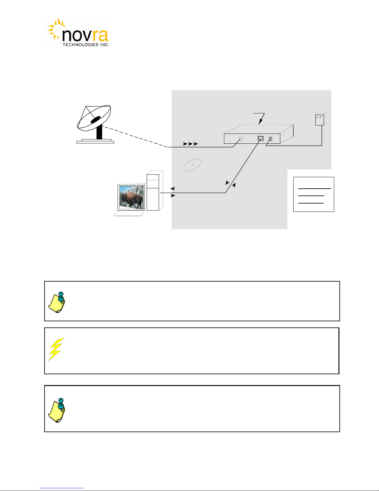
3.1What your configuration may look like................................................................................ 6
3.2What Information do I Need – Basic Configuration?........................................................... 7
3.3SOFTWARE Installation on Windows 2000, XP or Vista................................................... 8
3.4S75 Startup and Main Screen................................................................................................ 9
3.4.1S75 Main Screen............................................................................................................. 12
4Configuring the S75.................................................................................................................... 15
4.1Interfaces............................................................................................................................. 15
4.1.1Network Button............................................................................................................... 15
4.1.2Satellite Button................................................................................................................ 16
4.2IP Data Content Button....................................................................................................... 19
4.3A/V...................................................................................................................................... 20
4.3.1Content Button................................................................................................................ 21
4.3.2Program Association Table (PAT) Button...................................................................... 23
4.4Control ................................................................................................................................ 24
4.4.1Conditional Access Module (CAM) Button................................................................... 24
4.4.2Traps Button.................................................................................................................... 25
4.4.3Reboot Button................................................................................................................. 25
4.5File Drop Down .................................................................................................................. 26
4.6Control Drop Down ............................................................................................................ 27
4.7Video Wizard Drop Down.................................................................................................. 28
4.7.1How to Configure the S75 for TV Viewing.................................................................... 29
4.8Help Drop Down................................................................................................................. 31
4.8.1Help................................................................................................................................. 31
4.8.2About............................................................................................................................... 31
5How to Configure the S75 for TV Viewing................................................................................ 32
6Troubleshooting.......................................................................................................................... 35
7Specifications.............................................................................................................................. 36
7.1Receiver Characteristics...................................................................................................... 36
7.2Minimum System Requirements......................................................................................... 37
7.3Supplied Equipment............................................................................................................ 37
APPENDIX Terms, Definitions, and Tidbits of Information 38

Version: 2.0 Confidential and Proprietary 4of 40
1 Conventions
1.1 Text Conventions
Text appearing in Courier font indicates characters to be typed in; e.g. type Shell indicates that
the word “Shell” must be entered exactly as it appears, with the first letter capitalized.
Text appearing in Bookman Old Style font indicates a directory path or filename; e.g. c:\Program
Files.
Text appearing in SMALL CAPS and CopperPlate32BC font in an instruction indicates a button that
must be clicked, or a key that must be pressed, or a field that must be entered or a particular screen;
e.g. BUTTON indicates a button that must be clicked.
1.2 Applicable Models
This manual is applicable to the following S75 Models:
Novra S75CA
Novra S75+
Novra S75-Pro
1.3 Model Naming Convention
This manual uses the S75 naming convention when referring to any one of the applicable S75 models (see
Section 1.2).
NOTE: Information in this box
will be Informative.
CAUTION: This information
will be quite important and
should not be i
g
nored.
NOTE: - This manual covers all of the models listed in Section 1.2 above. The S75 Console
will automatically detect the type of receiver you are configuring and gray out console tabs
that are not needed to configure your particular receiver type.

Version: 2.0 Confidential and Proprietary 5of 40
2 Introduction
2.1 Principles of Operation
Somewhere in the world is a location that transmits your signal, along with many others, up to a
satellite that bounces those signals back down to your location, and others. Your satellite dish
catches all these signals, and the electronics at the dish converts them all into a group that travels
down the cable to your S75 receiver. The S75 sifts through all the signals sent by the satellite looking
for your signal (a DVB stream) and forwards to your computer the portion containing the data you
want. The Ethernet card on your computer can further filter that data and pass it to other programs on
your PC.
The S75CA provides a DVB conditional access common interface slot to enable the use of industry-
standard, PCMCIA-based, Conditional Access Modules (CAMs). This allows the user to use properly
configured, conditional access smart cards to receive DVB encrypted streams from the satellite.
The S75 Management Console is used to configure addresses, specify satellite tuning parameters,
specify decryption parameters, select DVB information streams by Program IDentification number
(PID) and map audio/video PIDs to multicast address(es). Once configured, the S75 will retain its
settings and continue to forward data transmitted to you by your service provider even after restarting
the S75 or your PC.
The S75 Receiver does not require a computer to continue operation. Once the options have been
set you will have no need to change them.

Version: 2.0 Confidential and Proprietary 6of 40
3 Getting Started
3.1 What your configuration may look like
CAUTION: Nothing should be inserted between the S75 and the satellite dish except for a
surge suppressor. Cable TV Splitters, TVs, VCRs, and FM receivers are not designed for
connection to this portion of the network. It is very likely they will be damaged by the LNB DC
voltage generated by the S75
24 Vdc
(Center +ve)
Power
Supply
Received Signals
The Receiver directly
controls and powers
the LNB
(Cat 5
Crossover
Cable)
Installation
Disk
Ethernet
Packets to/from
Mgmt Station
S75CA Receiver
The S75CA
Receiver
Package
NOTE: - This information is needed in order for the receiver to function. It is recommended
that all the information be collected before attempting to install the service. Novra
Technologies Inc. expects that end users, who wish to control the LNB with the receiver,
already have good understanding of satellite technology.
Figure 1: Typical Configuration
CAM Slot
NOTE: - Prior to removal of the smart card while running a live stream, it is recommended
that the S75CA be powered down for 10 seconds, or that the Conditional Access Module
(CAM) is first removed from the S75CA. To re-insert the smart card while running a live
stream, it is recommended that the smart card be first inserted into the CAM and then the
CAM be inserted into the S75CA.

Version: 2.0 Confidential and Proprietary 7of 40
NOTE: IGMP is an Internet standard that is used to control multicast traffic on the LAN
based on the client’s interest in the stream. For proper operation, all components of
your network should support IGMP
NOTE: The 22 KHz or 44 KHz tone is used to switch between the 2 bands of the LNB.
The receiver should be configured so that the proper tone is used and the proper band
is selected.
NOTE: If the LNB does not have the ability to switch polarizations, choose a value that
will provide the most suitable power supply voltage. In most cases this will be
Horizontal / Left (+15 or +18 Volts).
3.2 What Information do I Need – Basic Configuration?
Before using the S75 configuration software to configure your receiver, you need to gather the
following information:
1) The LO Frequency in MHz of the stream you wish to receive.
2) The RF Band Frequency in MHz of the stream you wish to receive.
3) Polarization: Horizontal / Left __ (+15, 18 or 20 Volts DC) OR Vertical / Right____(+11, +13, or
12 Volts DC)
4) Will the receiver be controlling a Single Band LNB (Most Common) or a Universal Band / Dual
LNB?
5) The Symbol Rate in Msps.
Examples: 21.096, 5.12600, 1.00, …etc.
6) The IP Address to be assigned to your Novra S75 Receiver
Example: 192.168.170.125
7) The IP address of the Default Gateway for the receiver.
8) Is the receiver supposed to filter multicast traffic using IGMP?
NOTE: Local Oscillator Frequency is specific to the LNB Model and is usually
stamped on the Unit or can be found in the LNB Manual. Typical values include: 9.75,
10.60, 10.75, 11.00, and 11.25 GHz for the Ku band. And for the C Band satellite
frequencies a typical value is 5.15 GHz.

Version: 2.0 Confidential and Proprietary 8of 40
3.3 SOFTWARE Installation on Windows 2000, XP or Vista
The S75 Console software is supplied as a single executable. Therefore, it is easy to install on
different systems. All you need to do is copy the executable to your working directory.
NOTE: - You MUST be logged onto the system as Administrator.
NOTE: - Your screen resolution MUST be at least 800 x 600 and at least
"16 bit color" to function properly.

Version: 2.0 Confidential and Proprietary 9of 40
NOTE: - You MUST be logged onto the system as Administrator, for the
network settings function to work properly.
3.4 S75 Startup and Main Screen
1- Start the S75 Console software.
2- The software will attempt to auto-detect all the receivers currently connected to the LAN. After the
auto detection is complete, a screen showing all discovered devices will be displayed as shown
below. Double click on the device that you wish to configure.
Figure 2 - S75 Device Listing
3- The first step in configuring your S75 is to ensure the network settings of the device make it
accessible from the Windows management PC. The IP address of the device and the IP address of
the management station must reside on the same subnet, or must be a route that connects both of
them through a router. If this is NOT the case, you will be prompted with the Change IP Address
Screen as shown below in Figure 3. You will need to change the IP address of your management PC
to be on the same subnet as the receiver (in this case, change your PC IP address to: 192.168.0..xxx,
where xxx is not equal to 250)

Version: 2.0 Confidential and Proprietary 10 of 40
NOTE: - Default Password is Novra
Figure 3 – Change IP Address Screen
4- If more than one receiver is found on the LAN you will be prompted to select one of them. Check
the MAC address to make sure you are connecting to the desired receiver.
5- Note: If there is an S75 receiver accessible on your network, but not on your local LAN you can
still configure it as if it were on your local LAN. In the Managed List section of the screen above,
enter the IPE address of the receiver you wish to configure in the IP field. You can also provide
an optional name beside it if you wish. Once the IP address is entered, click Add to add the IP
address to the Managed List. Now double click the IP address you just added to run the
Configure Application on the receiver. You can use the Add, Delete, and Delete All buttons to
add/remove entries in the Managed List.
6- Once you have selected your receiver, you will be prompted for a password. The default
password that you can use with your new receiver is: Novra.
Figure 4 – S75 Login Password Screen

Version: 2.0 Confidential and Proprietary 11 of 40
7- After successfully entering the password, you will be presented with the S75 Consol main screen
(as shown below).

Version: 2.0 Confidential and Proprietary 12 of 40
3.4.1 S75 Main Screen
Figure 5 - S75 Console Main Screen
As can be summarized from the figure above, the main page is divided into several sections. These sections
include:
1. At the top is a drop down menu that provides access to the File menu items, the S75
Configuration menu items, a Video Wizard and the Help screen
2. Below this, are the tabbed buttons that also provide access to the various configuration
menus. The tabbed buttons are also grouped based on functionality.
i. The Interfaces button group (Network, Satellite and CAM) allows configuration of the
network, satellite and CAM interfaces.
ii. The IP Data button group enables the operator to configure the receiver to receive
Multi-Protocol Encapsulation (MPE) data and pass or map this data onto the LAN.
The optional I/P Remapping function button is shown as being grayed out in the
above screen shot. The ability to remap received IP Multicast traffic to a new ip
address/port is only available as an option by special request. Please contact Novra
I
2
3
7
4
6
5

Version: 2.0 Confidential and Proprietary 13 of 40
NOTE: - Typically the IP Data function is used to configure the S75CA to
receive and re-distribute IP data, while the A/V function is used to configure
the S75CA to receive and re-distribute video programs.
Support for further information on how to receive this functionality on your S75
receiver.
iii. The A/V button group (Content and PAT) provides standard and advanced features
enabling the operator to receive MPEG transport stream packets and pass these
packets to Multicast addresses on the LAN.
iv. The last button group, entitled Control, provides additional configuration items that
include unit Reboot.
3. The middle bar of this screen displays the IP address and MAC address for the selected S75
being configured.
4. Status information on the operation of the S75 is provided in the lower part of the screen.
This status includes:
i. Status – Turns green when the status packets are being successfully received from
the S75 by the S75 console.
ii. Signal – Turns green when the receiver detects an input RF signal at the selected
frequency. This matches Signal LED on the front of unit.
iii. Data – Turns green when the S75 has achieved data lock. This means that the
receiver is able to recover all the digital timing from the input signal and is receiving a
valid DVB transport stream. This matches the Data LED on the front of the unit
iv. CA Module – Turns yellow when the S75CA detects a valid CAM in the PC slot.
Turns green when the S75CA detects a valid Program Association Table (PAT) on
the incoming stream.
v. LNB – Turns green when the LNB is turned on and is gray when the LNB is turned
off. The LNB status LED will also turn red if there is a DC short present on the RF
connector input.
vi. Signal Strength – Provides a graphic indication of the signal power at the input of
the receiver. The signal strength is shown as both a bar graph and percentage
strength.
vii. Viterbi Code Rate – Indicates the Viterbi code rate of the input stream. This number
is only valid when the receiver is locked.
viii. Viterbi BER – indicates the receiver Viterbi Bit Error Rate (BER) of the input stream.
This number is a true measure of the signal quality.

Version: 2.0 Confidential and Proprietary 14 of 40
NOTE: The counters will keep accumulating as long as the window is open. You can
use the reset buttons to reset the counters
ix. Uncorrectables –. The number of uncorrectable packets that were processed by the
demodulator section of the receiver. The counter accumulates and can be reset
using the Reset button located beside the Uncorrectables field.
x. Freq Error – Provides the difference between the desired RF frequency and the
tuned value.
5. Minimize – To the system Tray
6. Close – Close the S75 Console
7. Traffic Counters – The S75 provides a number of traffic counters that are useful in
determining the health and operation of the receiver.
i. Total Ethernet Packets Sent: This counter accumulates the total number of packets
being sent from the Ethernet port on the receiver.
ii. Ethernet Transmission Errors: This counter accumulates the number of errors that
happen during an Ethernet packet transmission at the receiver.
iii. Total Ethernet packets received: The number of Ethernet packets that the S75
received on the Ethernet interface.
iv. Ethernet Receive Errors:The number of errors that occurred during the reception of
Ethernet packets.
v. Ethernet packets Dropped: the number of packets that the S75 couldn’t transmit
due to lack of buffers, or irresolvable address.
vi. DVB Packets Accepted: The number of DVB packets that the receiver accepted and
processed.
vii. DVB Packets Descrambled: The number of clear or descrambled DVB packets that
the receiver accepted.
viii. DVB Packets Not Descrambled: The number of scrambled DVB packets that the
receiver accepted.
ix. DVB packets with bad Sync: Number of packets that didn’t have a proper
synchronization byte.

Version: 2.0 Confidential and Proprietary 15 of 40
NOTE: When editing field lists (such as PID lists), you can often edit or delete the list
entries by right clicking on them.
Pressing Esc on the keyboard when configuring the S75 has the same effect as
selectin
g
Exit.
4 Configuring the S75
This chapter discussed how to configure the S75. It covers both the drop down menus as well as the
configuration buttons.
4.1 Interfaces
The Interfaces group of buttons enables the operator to configure the 2 key interfaces on the S75, namely the
LAN or Network interface and the satellite or L-Band interface. These are both discussed further below.
4.1.1 Network Button
The network settings of the S75 may be modified by selecting the Network Button and changing the
appropriate fields (as shown below).
Figure 6: Network Configuration Dialog Box

Version: 2.0 Confidential and Proprietary 16 of 40
NOTE: - Proper operation of IGMP protocol requires that all devices used in the
network support IGMP protocol.
NOTE: The Device status can be sent to a remote management station by
configuring the status destination IP and port. However these settings don’t affect
the broadcast status messages. To turn off the unicast status, set the destination
IP address to 255.255.255.255
NOTE: - To turn off the status packets being sent to a unicast destination IP
address, set the Status Destination IP to 255.255.255.255.
1. Receiver IP: This is the IP address to be assigned to the receiver.
2. Subnet Mask: This is the subnet mask that the receiver should use to determine whether an IP
address belongs to the same network or not.
3. Default Gateway: This is the IP address of the router that the receiver should use whenever it
wants to send traffic to a non-local address.
4. Enable IGMP Filtering: This check box allows the user to turn IGMP filtering on or off. IGMP
controls which multicast streams will be forwarded on the LAN based on the number of clients
listening to that stream.
5. Status Destination port: This is the UDP port used to send a copy of the status packets for
remote monitoring applications
6. Status Destination IP: This is the IP address used to send Unicast status copies for monitoring
purposes.
7. Apply: By pressing this button, the updates are sent to the receiver
8. Exit: Exits back to the main screen
4.1.2 Satellite Button
The next step in the configuration is to ensure you have the correct RF settings and that the S75 can
successfully lock to your satellite signal. To configure your satellite settings, select the Satellite Configuration
Button and input the following fields:

Version: 2.0 Confidential and Proprietary 17 of 40
NOTE: - The LNB voltage level may be set by selecting the LNB
Parameters button.
Figure 7: Satellite Configuration Dialog
1) Symbol Rate: This is the symbol rate of the transponder that you are trying to tune to.
2) Receive Frequency: The RF Frequency of the signal that you are trying to receive.
3) LNB Power On: Turns the DC voltage and tone outputs of the receiver to ON or OFF.
a. Polarization: Switches the DC output of the receiver between Horizontal/Left and
Vertical/Right. This setting is only valid if the LNB power is on.

Version: 2.0 Confidential and Proprietary 18 of 40
NOTE: - The LNB tone frequency may be set by selecting the LNB Parameters
button.
NOTE: - If a dual LNB is being deployed, ensure that the appropriate LO
frequency is entered in the LO Frequency box and that the correct band (high or
low) is selected in the Satellite screen.
b. Band (Tone): Switch the LNB Tone frequency of the receiver On (High) or Off (Low). This
is only valid if the LNB power is on.
4) LNB Parameters: Used to set the LO frequency, polarization voltage and LNB tone (see Figure
below):
a. LO Frequency: Input the single-band LO frequency in MHz.
b. Polarity Switching Voltage: Select either11-15 Volts, 13-18 Volts or 12-20 Volts for the
Vertical/Right and Horizontal/Left LNB voltage values.
c. High/Low Band Tone: Select either 22 KHz or 44 KHz for the LNB switch tone frequency.
d. Long Line compensation: Checking this box will increase the Polarity Switching voltage
by 1 V. This additional voltage may be used to compensate for the voltage drop due to a
long I/F cable run between the S75 and the LNB.
e. OK: By pressing this button, the screen updates will be temporarily stored and the user will
be returned to the Satellite screen. By selecting Apply on the Satellite screen the LNB
Parameter settings will be sent to the S75. Selecting Exit will exit the Satellite screen
without setting the LNB Parameter updates.
f. Cancel: Exits back to the satellite dialog screen
5) Apply: By pressing this button, the updates are sent to the receiver.
6) Exit: Exits back to the main screen

Version: 2.0 Confidential and Proprietary 19 of 40
Figure 8 - LNB Information
4.2 IP Data Content Button
The IP Data Content button screen (shown below) is to be used when the S75 is to be configured to receive
MPE or IP data from the satellite stream and forward this data to the appropriate IP address on the LAN. This
screen is used to add (or delete) the data Program IDs (PIDs) that enable the S75 to receive the IP content.

Version: 2.0 Confidential and Proprietary 20 of 40
NOTE: - The keyboard may be used to add and remove PIDs. Also, to edit or
delete the PID list, right click on the list entry
Figure 9: IP Data Content PIDs
1. PID: Use this edit box to add a new Program ID to the list; you can use decimal input or
hexadecimal values preceded by “0x”.
2. ADD: This button adds the content of the PID box to the PID List.
3. Delete: This button deletes the selected PID from the PID list.
4. Delete All: This button will empty the PID list.
5. Apply: By pressing this button, the list will be sent to the receiver.
6. Exit: Exits back to the main screen
4.3 A/V
The A/V button group enables the operator to receive MPEG audio/video data by adding selected MPEG
PIDs to the received PID program list. If your receiver is configured as a PRO model, then you will also be
able to generate a new Program Association Table (PAT) for each received program (refer to Section 4.3.2 on
the PAT and Section 4.7 on the Video Wizard Drop Down).
This manual suits for next models
1
Table of contents
Other Novra Receiver manuals