Novus TagTemp-USB User manual

NOVUS AUTOMATION 1/6
TagTemp-USB
TEMPERATURE LOGGER – INSTRUCTIONS MANUAL
V1.0x E
CE Mark
This is a Class A product. In a domestic environment, this product may cause radio interference in which case the user may be required to take
adequate measures.

NOVUS AUTOMATION 2/6
1INTRODUCTION
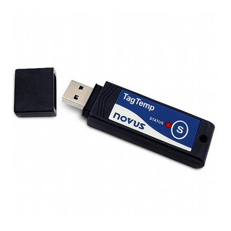
TagTemp-USB is a small portable electronic temperature logger. Its
internal sensor measures local environment temperature and logs
such values in an electronic memory. Logged data, or
ACQUISITIONS, can be later viewed and analyzed on a PC where
they can be opened in tabular and graph forms.
The LogChart II software enables to set up the device operation mode.
It is also used for viewing acquisitions. Other parameters such as end
of measurements, logging interval, etc., are easily defined through the
LogChart II software.
Acquisitions can also be exported to be analyzed in other
applications, such as spreadsheet programs.
1.1 IDENTIFICATION
The identification label is on the device body. Check if the features
described are in accordance with your order.
Fig. 01 – Front view of the device
Status indicator:This visual indicator reports the status of operation
of device through the number of flashes that occur in an interval of
five seconds. The states of operation are:
•One flash: The device is waiting to start the log in memory
(standby) or completed a series of logs in memory;
•Two flashes: the device is performing logs in memory;
•Three flashes: the device is or has gone through an alarm
condition and is not performing logs in memory;
•Four flashes: the device is or has gone through an alarm
condition and is performing logs in memory.
2TECHNICAL DATA
Measure Range Temperature: –20.0 °C to 70.0 °C.
Accuracy
±0.5 °C @ 25 ºC.
±1 °C max. along the entire measured
range.
Note: A measure error can be fixed using
the OFFSET parameter in the LogChart II
software.
Measurement
Resolutions Temperature: 0.1 °C.
Memory capacity 32.000 (32 k) logs.
Measurement
Interval
5 seconds min.
18 hours max.
Supply 3.0 V lithium battery (CR2032), built-in
Estimated battery
autonomy
•More than 400 days – Sampling rate
of 1 minute.
•More than 500 days – Sampling rate
of 30 minutes.
Operating
temperature From -20 °C to 70 °C
Case PC-ABS
Protection
Product suitable for applications requiring
up to IP67
degree of protection. See
chapter SPECIAL CARE.
Dimensions 55 x 37,5 x 15 mm
Device - PC data
transfer time
Proportional to the number of records. 20
seconds to 32,000 records.
PC Interface Micro-USB cable
LogChart ll
software operation
environment
Configurator software for Windows ® 8, 7
and XP.
Menus in Portuguese, English or Spanish.
Sets up, reads and displays data on the
screen.
Certification CE
3OPERATION
It is only possible to operate the device after the LogChart II
software is installed to a PC, according to the steps described in
LOGCHART II SOFTWARE chapter of this manual. The
communication between device and PC is performed with the aid of
the micro-USB cable.
The device operation mode set up is defined in advance by using the
LogChart II software.Each setting must be defined and the
consequences observed.
The device starts and stops logging as defined in settings.

NOVUS AUTOMATION 3/6
4LOGCHART II SOFTWARE
4.1 INSTALLING LOGCHART II
The LogChart II, application is used to configure the parameters for
data transfer. To install the LogChart II, run the file LC_II_Setup.exe
available on our web site.
4.2 RUNNING LOGCHART II
When you open LogChart II,the main window is displayed.
Fig. 02 – LogChart II main window
Next, select the serial port that the communication interface will use
in the Port menu.
Check which serial is available (usually COM2 is free). The chosen
port will be chosen by default next times the LogChart II is initiated.
When a valid port is selected, the icons below are displayed:
Fig. 03 – Icons enabled when the communication port selected is a valid port
4.3 CONFIGURING THE DEVICE
For device configuration is necessary that the communication
interface is connected to the computer, using the selected port
described in the previous section. See figure below:
Fig. 04 – Communication via USB cable
In order to mitigate problems, insert or remove
the USB cable carefully.
If you find it difficult to connect, make sure
that the cable is properly seated. No use of
force is required.
After the serial port is selected, click on the button:
The Parameters Configuration screen is displayed. In this screen,
the user can define the device operation mode and also obtains
general information about the device.
Fig. 05 – Configuration window
Fields are:
1 - Title: In this field, the user identifies the device by assigning it a
name.
2 - General information: Area with information about the device,
such as Model, Serial Number, Data Logger Date/Hour, Actual
Date/Hour, Firmware Version, Memory Capacity and Number of
acquisitions (stored in memory).
In this field, time is constantly updated while the communication
between device and computer is taking place.
3 - Readings: Presents a series of parameters that define the
acquisition process.
Interval: Defines the interval between readings: The minimum
interval is (5) seconds and maximum is (18) hours.
Note: When the type of value logged is minimum, maximum or
average values, the minimum interval is 50 seconds.
Estimated time: In this parameter, the device informs the user
how long it will take to occupy the full memory, in the conditions
set up during configuration.
Start of Readings: Readings can be started in one of three
different modes:
•Immediately: Start as soon as set up is ready and sent
(OK) to the device.
•Date: Readings start at predefined date and time.
•Setpoint: Acquisitions start when a temperature
setpoint is reached. In this option, the setpoint value is
defined in the Channels field, where the Alarm
parameter is replaced by setpoint.
Stop loggings: Options for the end of readings are:
•Full Memory: Readings can be stored up to the full
memory capacity is reached.
•Don’t stop (Wrap around): Readings are continuous,
replacing old records with new ones as the number of
readings overpasses the memory capacity.

NOVUS AUTOMATION 4/6
4 - Channels: Displays other parameters related to temperature
measurement:
Fig. 06 – Configuration window
Unit: Defines the unit of the value measured: ºC or ºF for
channel 1 (temperature).
Value: It defines how the value measured will be registered.
Options are:
•Instantaneous: The value logged will be exactly the value
measured at each interval defined. Measurement is taken
at the end of the defined interval. The minimum interval
between measurements is 5 seconds.
•Average: The registered value will be the average of 10
measurements made on logging interval. The minimum
time between each record is 50 seconds.
•Maximum: The value logged will be the maximum value
found within 10 consecutive measurements taken within a
predefined interval. The minimum interval between
measurements is 50 seconds.
•Minimum: The value logged will be the minimum value
found within 10 consecutive measurements taken within a
predefined interval. The minimum interval between
measurements is 50 seconds.
Offset:Makes possible to correct the value logged.
Alarm: Defines limit values that, when exceeded, characterize
an alarm condition. Alarm events are informed to the user
through a flashing mode of the Alarm Indicator.
After filling all the fields, select OK and the settings will be sent to the
device.
4.4 STOP / PAUSE / RESUME BUTTONS
These buttons will be enabled once the device is fully configured.
The Stop button allows stop records permanently, so that the device
will only register again after a new configuration by the user.
The Pause / Resume button action sends the appropriate command,
depending on the current registration status:
If the records are In Progress and pressing this button, it will be
send a command to Pause the records.
Pause: Pauses the registry, allowing it to be resumed later using the
Resume button.
If registration is Paused and pressing this button, it will be send a
command to Resume the records.
Resume: Resumes the records that were interrupted by the Pause
command without erasing the previous registers of the device
memory, using the same parameter settings previously configured.
5DOWNLOAD AND DATA VISUALIZATION
Downloaded data are send from device to PC. Data can be
downloaded any time at the end of the acquisition process or while
they are being acquired. If data downloaded takes place during the
acquisition process, the process will not be interrupted, following the
device configuration.
5.1 DOWNLOADING DATA
Data download is accomplished by clicking the button Download
Data:
During data transference, a status bar indicates remaining data to be
transferred. Data downloading time is proportional to the number of
readings logged.
5.2 VISUALIZING DATA
At the end of values transfer, data can be displayed in a graphical
form.
5.2.1 Chart Window
It is possible to select a region of the chart to zoom in. Zoom
commands can be accessed through the View menu or through
zoom icons from the task bar.
It is also possible to select an area from the chart to zoom in by
clicking and dragging the mouse, thus creating a zoom region
starting from the upper left corner on the chart area.
The graphic curves can be vertically dragged with a right-click and
dragging the mouse up and down.

NOVUS AUTOMATION 5/6
Fig. 07 - Chart window
5.2.2 Measures Table Window
To display measurements in a tabular form, press the icon Table
View:
Values are presented in a tabular form, listing the measurement time
and value.
Fig. 08 – Screenshot showing the measurement table
5.2.3 General information table
This window shows some information about the device whose data
were just read and its configuration. The screen can be displayed by
pressing the icon Parameter Viewing:
Fig. 09 – General information window
5.3 EXPORTING DATA
Downloaded data can be exported to different file formats for further
analysis. To export, access File/Export or click the icon:
5.4 DIAGNOSTICS
Battery Level: Indicates the level of battery voltage. When the
battery reaches a low level voltage, immediate replacement is
recommended to ensure that the device will be continue to function
properly.
Device Status: Summarizes the state of the device, including its
memory, and the occurrence of alarm events to the time of the
opening of the Diagnostic page.

NOVUS AUTOMATION 6/6
6BATTERY REPLACEMENT
Replace battery with Panasonic lithium battery
Part No. CR 2032 only.
Usage of another battery may present a risk of
fire or explosion.
Replacement procedure is described as follows:
•Remove the plastic cover.
Fig. 10
•With a small screwdriver, carefully remove the circuit board and
battery
Fig. 11
•Insert a new battery and reattach the electronic board in the
cabinet.
Fig. 12
•Carefully connect the USB connector into the housing with the
battery downward.
Fig. 13
7MOST FREQUENTLY FOUND PROBLEMS
The LED is not flashing: The LED flashing light is intentionally weak
and it can be difficult to see it in clear environments. Certify it is really
not flashing.
Communication with the device fails:
Make sure the COM port is selected correctly and there is no other
program using the same port during communication attempts.
Make sure there is no physical obstacle blocking the infrared signal.
Make sure the cable is well connected to the PC port.
Make sure the port selected does not present any problem.
8SPECIAL CARE
When handling the device and its battery, observe the following:
•When the device is opened, avoid touching the electronic
components and the printed circuit board to avoid electrostatic
discharge damages.
•Pay close attention to battery polarity.
•When closing, the cover and its sealing must be mounted
correctly and carefully to ensure the enclosure sealing.
•Used batteries must be disposed in accordance to local
regulations. Don’t try to recharge, dismount or heat, since
explosion may occur.
9WARRANTY
Warranty conditions are available on our web site
www.novusautomation.com/warranty.
Table of contents
Other Novus Data Logger manuals

Novus
Novus TagTemp-NFC User manual

Novus
Novus TagTemp User manual

Novus
Novus TagTemp - USB User manual

Novus
Novus TagTemp-NFC User manual

Novus
Novus LogBox-RHT-LCD User manual

Novus
Novus LOGBOX User manual

Novus
Novus LogBox-AA-32k-IP67 User manual

Novus
Novus LogBox-DA User manual

Novus
Novus LogBox-AA User manual

Novus
Novus TagTemp Stick User manual