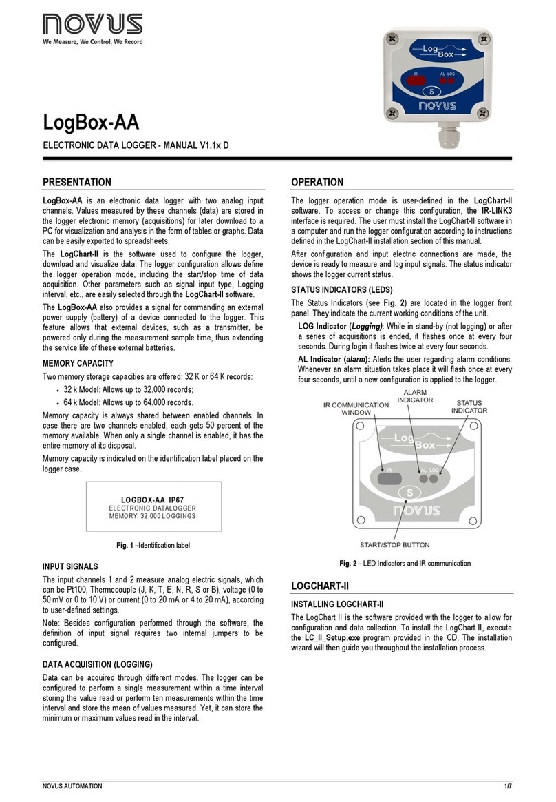
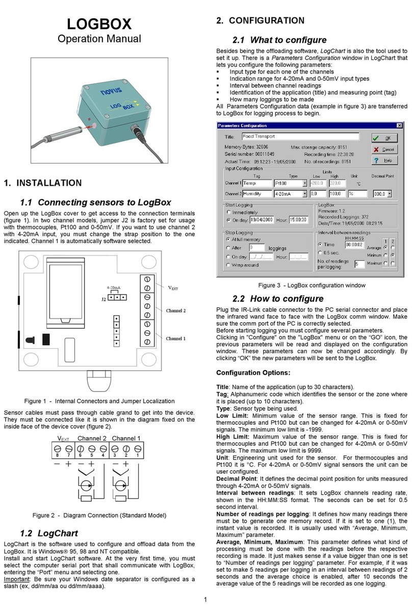
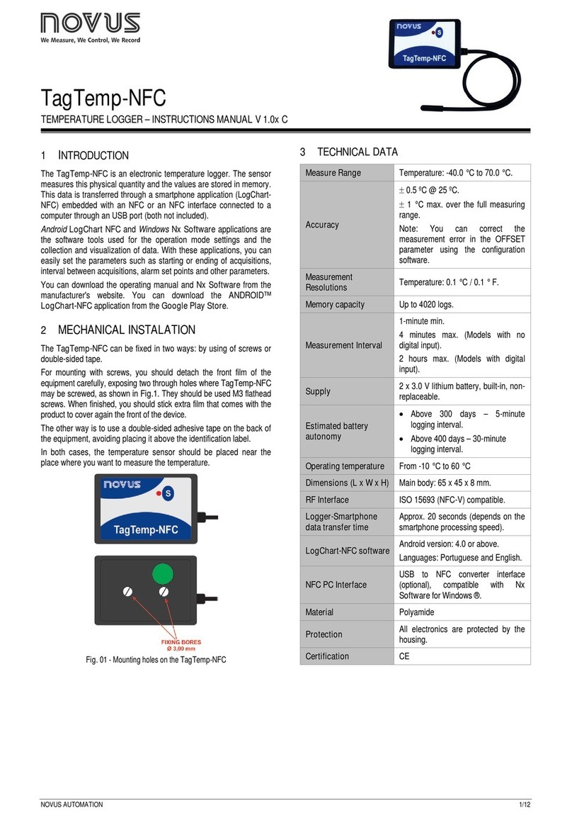
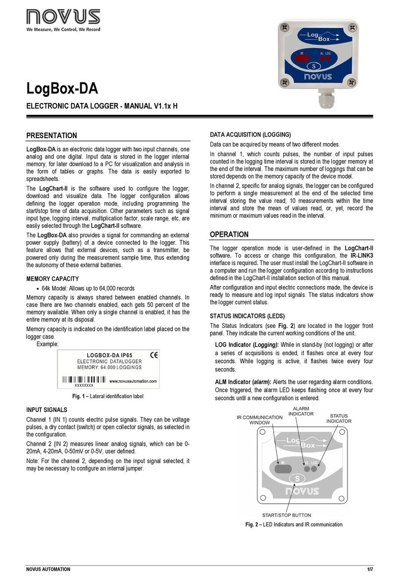
Novus TagTemp User manual

NOVUSAUTOMATION UK TEL: + 44 (0) 870 321 8522FAX: + 44 (0) 870 321 8523 web: www.novusautomation.co.uk email: [email protected] | 1/7 1/7
TagTemp
TEMPERATURE LOGGER – INSTRUCTIONS V 1.1x
1INTRODUCTION
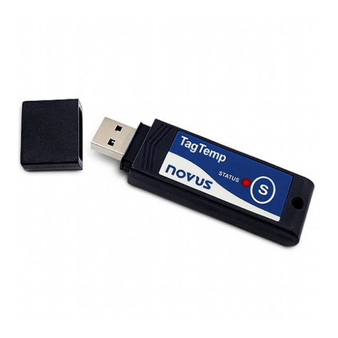
TagTemp is a small portable electronic temperature logger. Its
internal sensor measures local environment temperature and logs
such values in an electronic memory. Logged data, or
ACQUISITIO S, can be later viewed and analyzed on a PC where
they can be opened in tabular and graph forms.
The logger is supplied with LogChar -II software, which enables to set
up the logger operation mode. It is also used for viewing acquisitions.
Other parameters such as end of measurements, logging interval, etc.,
are easily defined through the LogChar -II software.
Acquisitions can also be exported to be analyzed in other
applications, such as spreadsheet programs.
1.1 UNPACKING
The following items must be included in the package:
-The electronic logger TagTemp;
-A CD-ROM with the LogChart-II software and a USB driver;
-Quick logger operation guide.
-A communication interface upon request.
1.2 IDENTIFICATION
The identification label is on the logger body. Check if the features
described are in accordance with your order.
The following elements are shown in the logger front.
Figure 01 – Logger Front
S ar /s op bu on (S): This button “wakes up” the logger whenever a
communication between logger and PC is intended to start. It can
also be configured to start or stop the temperature measurement
process.
IR communica ion Window: PC - Logger communication area.
During download, the communication interface must be directed
towards this window.
S a us indica or (LOG): While in stand-by (not logging) or after a
series of measurements, it flashes once at every four seconds.
During logging it flashes twice at every four seconds.
Alarm Indica or (AL): Warns the user as to alarm conditions.
Whenever an alarm situation takes place it will flash once at every
four seconds, until a new configuration is applied to the logger.
2TECHNICAL DATA
Measure Range Temperature: –20.0 °C to 70.0 °C.
Accuracy
±
0,5 ºC @ 25 ºC.
±
2 ºC max. along the entire measured range.
ote: A measure error can be fixed using the
OFFSET parameter in the LogChart-II software.
Measurement
Resolutions
Temperature: 0.1 °C.
Memory capacity 16,000 (16 k) logs.
Measurement Interval 1 second min.
18 hours max.
Supply 3.6 V lithium battery (CR2032), built-in
Estimated autonomy Higher than 365 days, with weekly data
reading. Frequent logged data readings may
shorten battery life.
Operating temperature From -20°C to 70°C
Case Polycarbonate
Protection Suitable for products with protection level IP67.
See “Special Care” section.
Dimensions 30 x 47 x 0.47 mm
Logger-PC data transfer
time
According to the number of logs. 40 seconds
for 16,000 logs.
PC Interface Ir/USB or Ir/Serial
LogChart-ll software
operation environment
Set up Software for Windows 95, 98, T, 2000
and XP.
Menus in Portuguese, English or Spanish.
Sets up, reads and displays data on the
screen.
3OPERATION
It is only possible to operate the logger after the LogChart-II software
is installed to a PC, according to the steps described in LogChar -II
Sof ware section of this manual. The communication between logger
and PC is performed with the aid of the IR-Link wand.
The logger must be “waken up” before communication is attempted.
To do so, press the S ar /S op button.
The logger starts flashing the S a us Indica or according to his
current status:
•
One flash at every four seconds (stand-by) indicates the
logger is waiting to start measuring or that a series of
measures was concluded and the logger is waiting for a new
command.
•
Two flashes, measures ongoing.
The logger operation mode set up is defined in advance by using the
LogChar -II software. Each setting must be defined and the
consequences observed.
The logger starts and stops logging as defined in settings.

TAGTEMP logger
NOVUS AUTOMATION UK TEL: + 44 (0) 870 321 8522 FAX: + 44 (0) 870 321 8523 Web: www.novusautomation.co.uk email: [email protected] | 2/7
4LOGCHART-II SOFTWARE
4.1 INSTALLING LOGCHART-II
LogChart II is the software provided with the logger to allow for
configuration and data offload. To install, run the LC_II_Se up.exe
file provided with the CD-ROM.
ote: Be sure your Windows date separator is configured as a slash:
dd/mm/yy or dd/mm/yyyy.
4.2 RUNNING LOGCHART-II
When you open LogChart-II the main window is displayed.
Figure 3 – LogChart-II main window
ext, select the serial port that the communication interface will use
in the “Port” menu.
Check which serial is available. Usually COM2 is free, once the
mouse uses COM1. The chosen port will be chosen by default next
times the LogChart II is initiated. When a valid port is selected, the
icons below are displayed.
Figure 4 – Icons enabled when the communication port selected is a valid
port
4.3 CONFIGURING THE LOGGER
Make sure the communication interface is connected to the PC port
selected. The interface must be constantly directed towards the front
part of the logger (communication window) at a maximum distance of
1 m. (See Figure 05).
Figure 5 – Infrared communication interface position
The logger must be “waken up” by pressing the Start/Stop button.
After the serial port is selected, select:
The Parame ers Configura ion screen is displayed. In this screen
the user can define the logger operation mode and also obtains
general information about the device.
Figure 6 – Configuration window
Fields are:
1- Ti le: In this field, the user identifies the logger by assigning it a
name.
2- General informa ion: Area with information about the logger,
such as Model, Serial umber, Logger Date/Time, PC Date/Time,
firmware version, memory capacity and number of acquisitions
stored in memory, etc.
In this field, time is constantly updated while the communication
between logger and computer is taking place.
3- Readings: Presents a series of parameters that define the
acquisition process.
In erval: Defines the interval between readings: The minimum
interval is (1) second and maximum is (18) hours.
ote: When the type of value logged is maximum or minimum
values, the minimum interval is 10 seconds.
In Daily repe i ions the user defines the time that daily logs will
take place.
Es ima ed ime: In this parameter, the logger informs the user
how long it will take to occupy the full memory, in the conditions
set up during configuration.
S ar of Readings: Readings can be started in one of five
different modes:
•
Immedia ely: start as soon as set up is ready and sent
(OK) to the logger.
•
S ar via Palm: start with a command sent via PDA, which
runs the software Log Chart Palm-OS. For further
information, see PDA User section in this guide.
•
Da e: readings start at predefined date and time.
•
Via S ar /S op Bu on: starts and interrupts readings by
pressing the Start/Stop button, in the frontal part of the
logger, for two seconds. See Figure 01.
•
Se poin : acquisitions start when a empera ure setpoint
is reached. In this option, the setpoint value is defined in
the Channels field, where the Alarm parameter is replaced
by setpoint.
S op loggings: Options for the end of readings are:
•
Full Memory: readings can be stored up to the full
memory capacity is reached.
•
Don’ s op (Wrap around): readings are continuous,
replacing old records with new ones as the number of
readings overpass the memory capacity.
•
Af er: the logger stops readings after a certain number of
readings.

TAGTEMP logger
NOVUS AUTOMATION UK TEL: + 44 (0) 870 321 8522 FAX: + 44 (0) 870 321 8523 web: www.novusautomation.co.uk email: CustomerService@NovusAutomation.co.uk | 3/7
•
Da e: Readings stop at user-predefined date and time. In
case the logger memory capacity is reached before the
date defined, readings are stopped.
4- Channels: Displays other parameters related to temperature
measurement:
Uni : Defines the unit of the value measured: ºC or ºF for
channel 1 (temperature).
Value: It defines how the value measured will be registered.
Options are:
•
Ins an aneous: The value logged will be exactly the value
measured at each interval defined. Measurement is taken
at the end of the defined interval. The minimum interval
between measurements is 1 seconds.
•
Maximum: The value logged will be the maximum value
found within ten consecutive measurements taken within a
predefined interval. The minimum interval between
measurements is 10 seconds.
•
Minimum: The value logged will be the minimum value
found within ten consecutive measurements taken within a
predefined interval. The minimum interval between
measurements is 10 seconds.
Offse : Makes possible to correct the value logged.
Alarm: Defines limit values that, when exceeded, characterize
an alarm condition. Alarm events are informed to the user
through a flashing mode of the Alarm Indica or.
After filling all the fields select OK and settings will be sent to the
logger.
5INTERFACE INSTALLATION
In the Ir-Link3/RS232 model there is a RSR232/Ir communication
interface. It must be connected to the serial port at the PC.
In the Ir-Link3/USB model there is a USB/Ir communication
interface, which must be connected to the available USB port.
Windows will request the proper driver installation, which is found in
the CD-ROM that is provided with the logger.
5.1 USB DRIVES INSTALLATION
The drives installation steps may vary according to the machine,
even for the same version of an operating system. The following
screenshots and steps are only to provide guidance.
1. Insert the CD shipped with the logger in the CD-ROM
drive.
2. Connect the serial communication interface IrLink-3 to the
PC USB port. Windows® will acknowledge the presence
of new hardware and a few seconds later it will start the
drivers installation process.
3. The found new hardware wizard will be displayed, and
you will be asked if you want to install the driver from the
Windows Update website. Select “ o, not this time”, and
then click ext.
4. Select “Install from a list or specific location (Advanced)”
and click “ ext”.
5. Select “Search for the best driver in these locations” and
check “Search removable media”. Click “ ext”. If
installation files are not in a CD, check “Include this
location in the search” and show the file path.
6. If a prompt warns you that it does not support Windows®
XP, click “Continue anyway”.
7. The interface driver files will be copied to the computer
and after a few seconds a screen is displayed informing
that the software installation as been concluded. Click
“Finish”.
8. In some situations, the steps described above may be
repeated again. Follow the same procedures.
In later uses of the interface, Windows® may require the driver
installation again. In this case, the same installation wizard will be
displayed, and you will have to select the option “Install software
automatically (recommended), as the driver may already be in the
computer.
The following screenshots show examples of Windows XP®
installation wizard. The screens in Windows 2000 are slightly
different, but the content is basically the same.

TAGTEMP logger
NOVUS AUTOMATION UK TEL: + 44 (0) 870 321 8522 FAX: + 44 (0) 870 321 8523 web: www.novusautomation.co.uk email: [email protected] | 4/7
6OFFLOADING AND DATA VISUALIZATION
Data collected are send from logger to PC. Data can be collected any
time, at the end of the acquisition process or while they are being
acquired. If data collection takes place during the acquisition
process, the process will not be interrupted, following the logger
configuration.
It is important to "wake up" the logger before starting communication.
6.1 OFFLOADING DATA
Data offload is accomplished by clicking the button Offload Da a:
During data transference, a status bar indicates remaining data to be
transferred. Data offloading time is proportional to the number of
readings logged.
6.2 VISUALIZING DATA
At the end of values transfer, data can be displayed in a graphical
form.
6.3 CHART WINDOW
It is possible to select a region of the chart to zoom in. Zoom
commands can be accessed through the View menu or through
zoom icons from the task bar.
It is also possible to select an area from the chart to zoom in by
clicking and dragging the mouse, thus creating a zoom region
starting from the upper left corner on the chart area.
The graphic curves can be vertically dragged with a right-click and
dragging the mouse up and down.
Figure 07 - Chart window.
6.3.1 MeasureS Table Window
To display measurements in a tabular form, press the icon Table
View:
Values are presented in a tabular form, listing the measurement time
and value.
Figure 08 – Screenshot showing the measurement table
6.3.2 General informa ion able
This window shows some information about the logger whose data
were just read and its configuration. The screen can be displayed by
pressing the icon Parame er Viewing:
Figure 09 – General Information Window
6.4 EXPORTING DATA
Logged data can be exported to different file formats, for further
analysis. To export, access File/Export or click the icon:

TAGTEMP logger
NOVUS AUTOMATION UK TEL: + 44 (0) 870 321 8522 FAX: + 44 (0) 870 321 8523 web: www.novusautomation.co.uk email: [email protected] |5/7
7PDA USER
It is possible to set up the logger and collect acquired data with a
PDA that supports the Palm-OS system.
The application LogChar Palm-OS is shipped with the logger. The
stalled in the PDA through a HotSync process (data synchronization
between PDA and PC).
The user needs the Palm Desk op and the LogChar II software
installed in his machine. It is recommended to execute the Palm HotSync
before installing the LogChar PalmOS.
To install the software, insert the disk in the driver, click on Start and
Execute in the windows task bar. Type d:\LCP_Se up, where d: is
the disk driver unit. Press “OK”. The installation wizard will guide you
through the installation process.
Executing a new HotSync will install the LogChar PalmOs software
in the PDA. The LogChart icon will be added to the PDA home
screen.
Starting the LogChar PalmOS application will display the Recorded
Da a screen on the PDA. Starting the LogChart PalmOS application
will display the Recorded Da a on the PDA screen, where from it is
possible to access the logger to change settings and offload data, as
well as to access recorded data.
Figure 10 – Recorded Data screen
7.1 ACCESSING THE LOGGERS
To have communication between the logger and the PDA
established, the user must align the PDA infrared wand to the logger
communication window, run the LogChart Palm-OS software, wake
up the logger and press Search Device in the Recorded Da a
screen.
When the PDA finds the logger, the Moni oring screen will be
displayed. The screen displays values of variables measured,
configuration information and current logger status.
Figure 11 – PDA Monitoring screen
Buttons are assigned the following functions:
Search: It allows "searching" for another logger or reconnect
communication lost for any reason. After finding a logger, the PDA
displays a new Moni oring screen.
Download: Offload logged data. Download can be partial and it does
not interfere in the ongoing measurement process.
More Info: Displays further information on the connected logger,
such as model, serial number, version and memory capacity.
Se ings: Accesses the Settings screen, which allows for modifying
the logger configuration.
Da a Base: Displays the Recorded Da a screen listing all the
processes stored and processed in the PDA data base.
Figure 12 – Recorded Data Details screen
7.2 CONFIGURING THE LOGGER – SETTINGS
During configuration, the logger and the PDA ports must be aligned.
Press Se ings in the Moni oring screen. The screen Se ings is
opened and provides the required parameters for configuring the
logger.
Figure 13 – PDA Settings screen
The parameters to be defined are:
Ti le: ame of the process.
Inpu : Enables the user to select the temperature unit.
S ar (start of acquisitions): Defines the measurement start
mode. Options are:
Immedia ely: The logger starts logging as soon as
configuration is sent to the logger.
By da e/ ime: Start in defined data and time, always after
current time. It is possible to perform daily repetitions. If this
option is selected, a new box to define the stop logging time
is displayed.
By <S ar > Bu on: Press the S ar _Now button from the
Moni oring screen to start logging. The PDA must be turned
towards the logger.
By Se poin value: Measurements start when a temperature
setpoint is reached. With this option it is also possible to start
measurements above (log Above) or below (log Below) a
temperature setpoint (channel 1). This option is not valid for
alarms that have already been set up.
By TagTemp bu on: Starts when the S ar /S op button at
the frontal side of the logger is pressed.
S op: Defines the measurements stop mode: Options are:
Full memory: Loggings can be stored up o the logger full
memory capacity is reached.
Wrap around: Logging never stops. When the logger
maximum memory capacity is reached, oldest records are
overwritten by newest data.
Af er loggings: The logging will stop after the number of
readings are defined.
By da e/ ime: Logging is stopped on user-defined date and
time.

TAGTEMP logger
NOVUS AUTOMATION UK TEL: + 44 (0) 870 321 8522 FAX: + 44 (0) 870 321 8523 web: www.novusautomation.co.uk email: [email protected] | 6/7
In erval: Defines the interval between readings: hour, minutes
and seconds. When the logging mode is set to the
ins an aneous the minimum interval is 1 second. For maximum
and minimum values, the minimum interval is 10 seconds in
both models.
Misc: Shows the Logging Mode parameter that defines how
measured value will be logged. Options are:
Ins an aneous: The value logged will be exactly the value
measured at each interval. Measurement is taken at the end
of the defined interval. The minimum interval between
measurements is 1 second.
Minimum: The value logged will be the minimum value
found within ten consecutive measurements taken within an
interval. The minimum interval between measurements is 10
second.
Maximum: The value logged will be the maximum value
found within ten consecutive measurements taken within an
interval. The minimum interval between measurements is 10
second.
Alarms: Enables an alarm that is triggered according to user-
defined parameters. Values shown in the temperature unit
selected.
Figure 14 – PDA Alarm Settings screen
Clocks: Provides access to Logger and PDA clocks. When a
new configuration is sent to the logger, clocks are updated.
Offse : allows fine offset adjustment on the measured value. The
Rese button clears changes made and the logged values are
the measured values again.
Figure 15 – Offset adjust screen
After configuring clocks in the Se ings screen, click Apply to send
this configuration to the Logger, returning to the Moni oring screen.
Sending a new configuration implies the exclusion of all data
collected present in the logger memory.
7.3 DOWNLOADING DATA FROM THE LOGGER
In the Moni oring screen, the Download button performs the
transfer of the data from de LogBox to the PDA. Download can be
partial and it does not interfere in the ongoing acquisition process.
The data base of loggings is displayed in the Recorded Da a screen,
identified with the name assigned to the process (Da a Ti le) and the
date it was downloaded.
Should the PDA batteries be discharged, all readings will be lost.
7.4 FILE VISUALIZATION
The Recorded Da a screen lists the data base logged and stored in
the PDA. To access data, select the desired data base and press
De ails. Recorded Da a De ails screen shows several information
about the data base.
View Da a shows in table format the logged values and the date and
time they were performed.
Press Dele e to erase the selected data base.
7.5 TRANSFERRING DATA TO YOUR DESKTOP
HotSync of data stored in a PDA with the Desktop is performed
through a conduit installed together with the LogChart Palm-OS. The
conduit converts the data collected by the LogChart Palm-OS to a file
compatible with the LogChart-II software.
To access the conduit options, the Ho Sync Manager software must
be active. Click on the HotSync Manager in the Windows taskbar.
Select in the drop-down menu the option Custom. Select Novus
LogChar Condui and click Change. The following window will be
exhibited:
Figure 16 – LogChart Conduit options
Handheld overwri es Desk op: LogChar Palm-OS files are
transferred to the Desktop.
Save in: Choose a directory to record files generated during data
synchronization.
Leave Da a on Palm: Option to keep or delete the data in the PDA
after HotSync.
Do no hing: Data synchronization will not be performed;
Se as defaul : The same settings will be used in the next Ho Sync
processes.
8MOST FREQUENTLY FOUND PROBLEMS
The LED is no flashing: The LED flashing light is intentionally
weak, and it can be difficult to see it in clear environments, certify it is
really not flashing.
Communica ion wi h he logger fails:
Make sure the COM port is selected correctly and there is no other
program using the same port during communication attempts;
Make sure there is no physical obstacle blocking the infrared signal;
Make sure the cable is well connected to the PC port;
Make sure the port selected does not present any problem;
9SPECIAL CARE
When handling the device and its battery, observe the following:
•When the device is opened, avoid touching the electronic
components and the printed circuit board to avoid electrostatic
discharge damages.
•Pay close attention to battery polarity.
•When closing, the cover and its sealing must be mounted
correctly and carefully to ensure the enclosure sealing.
TAGTEMP logger
NOVUS AUTOMATION UK Tel: + 44 (0) 870 321 8522 Fax: + 44 (0) 870 321 8523 web: www.novusautomation.co.uk email: [email protected] |7/7
•Used batteries must be disposed in accordance to local
regulations. Don’t try to recharge, dismount or heat, since
explosion may occu
10 ADDITIONAL INFORMATION
If you have any doubt concerning this or other OVUS products,
www.novus.com.br.
11 WARRANTY
ovus Produtos Eletrônicos Ltda. products are covered by a 12-
month warranty provided the purchaser presents the sales receipt
and the following conditions are met:
♦
Products are covered for one year from the original date of
purchase. Please retain the dated sales receipt as evidence of the
date of purchase. You will need it for any warranty service
♦
Within this period, warranty against defects in material and
workmanship under normal use is free of charge.
♦
For repair, send the product and the sales receipt to our address in
Porto Alegre. Expenses and transportation risks are under the
purchaser’s responsibility
♦
This warranty does not cover any damage due to accident, misuse,
abuse, or negligence.
Table of contents
Other Novus Data Logger manuals

Novus
Novus LogBox-AA-32k-IP67 User manual

Novus
Novus LogBox-DA User manual

Novus
Novus LOGBOX User manual

Novus
Novus LogBox-AA User manual

Novus
Novus LogBox-RHT-LCD User manual

Novus
Novus LogBox-DA User manual

Novus
Novus TagTemp - USB User manual

Novus
Novus TagTemp-USB User manual

Novus
Novus TagTemp-NFC User manual

Novus
Novus TagTemp-NFC User manual