N1050 Controller
NOVUS AUTOMATION 3/11
alarm soon upon the process start-up, an occurrence that may be
undesirable.
The Initial Blocking is disabled for the i.err function.
RUN FUNCTION
The RUN function allows you to enable and disable the device
operation. It works like a general key.
When in the on condition (RUN = YES), the controller is enabled to
operate, and the control outputs and the alarm are acting normally.
When in the off condition (RUN = No), the controller does not act on
the process, summarily switching off its outputs. No function is
performed and only the measured temperature indication remains
operative.
Function available in the RUN parameter in the controller Operation
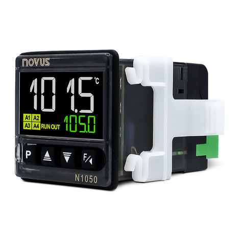
cycle. The RUN indicator on the frontal panel of the controller turns
on when the control is enabled (RUN = YES).
SAFE OUTPUT FUNCTION WITH SENSOR FAILURE
Function that ensures that the control output is in a safe condition for
the process when an error in the sensor input is identified.
When a fault is identified in the sensor, the controller will determine
the percentage value set in the parameter iE.ou for the control
output. The controller will remain in this condition until the sensor
failure disappears.
When in ON/OFF mode, the values for iE.ou are only 0 and 100%.
When in PID mode, any value between 0 and 100% will be accepted.
LBD FUNCTION – LOOP BREAK DETECTION
The parameter Lbdt defines a time interval, in minutes, within which
the PV is expected to react to a control output signal. If the PV does
not react properly within the time interval configured, the controller
will signal the occurrence of the LBD event, which indicates control
loop problems, in its display.
An LBD event may be sent to any output channel. To do so, just
configure the desired output channel with the Lbd function which, in
this event, will be triggered.
The LDB function is disabled when the parameter is programmed
with 0 (zero).
This function is useful in detecting system failures, such us defective
sensors or actuators, loads and power supply, among others.
OFFSET
This feature allows a small adjustment to the PV indication. Also
allows you to correct measurement errors that appear, for example,
during the replacement of a temperature sensor.
TIMERS
The controller has two timers (T1 and T2), which operate
independently of the temperature control actuation.
The parameters that define the operation mode of these timers are
presented in the Timer Cycle.
The time count always starts with T1 and, at the end of it, starts the
T2 count.
The time base can be set as HH:MM or MM:SS in the parameter
T.tb.
Any of the controller outputs can be linked to the timers.
The special parameter (T.RUN) allows disabling the temperature
controller at the end of the timer.
The A3 and A4 indicators on the front of the controller are linked to
the conditions of the T1 and T2 timers, respectively.
TIMER T1
T1 is the main timer. Its operating mode is set with the configuration
of two parameters:
Behavior of the output timer.
Note 3: The T1 adjustment parameter can also be shown in the
Operation Cycle of the controller by parameter T1.e.
TIMER T1 TRIGGER
There are three Timer T1 trigger, available in parameter t.str:
Timer Start
Defines the start mode of the T1 timer.
Timer off (T1 and T2). The other parameters
related to the timer will not be displayed.
Starts the time count when the measured
temperature (PV)
temperature value set for the process.
Starts the time count via the key.
Once started, the timer will stop if the
key is pressed with a short touch (1 s). A
short touch will resume the timer. A long
touch (3 s) on the key will immediately
end the timer cycle in progress.
Note 4: The timer trigger via the
linked to the control condition enabled (
).
Starts the time count when the control is
enabled (
=
).
Note 5: The timer trigger via the key is linked to the control
condition enabled (RUN = YES).
Note 6: In the t.str parameter, the off option disables the T1 and
T2 timers and hides all parameters related to this feature.
BEHAVIOR OF OUTPUT T1 DURING T1
The T1 output has two different behavior possibilities during T1 timer.
The parameter t.end allows its definition.
The A3 indicator on the controller frontal indicates the timer current
step.
Timer End
Behavior of output T1 at the end of the T1 timer.
T1 output turns on (on) at the end of T1.
When starting the T1 timer, the T1 output
remains off. At the end of the timer, output T1 is
turned on and will remain on until a new cycle
starts.
The A3 indicator flashes during the T1 timer.
After T1, it is permanently On, indicating that
the output still on (see Note 7).
T1 output turns off (off) at the end of T1. In
this mode, the T1 output turns on at the start of
the T1 timer and turns off at the end of the T1
timer.
The A3 indicator flashes during the T1 timer
and turns off at the end of T1 (see Note 7).
Note 7: When the timer is interrupted by pressing the key, the
indicator (A3 or A4) will flash quickly.
TEMPERATURE CONTROL BEHAVIOR AT THE END OF THE
TIMER
During the timing of T1 and T2 intervals, the temperature control acts
according to its configuration and in an independent way. However,
at the end of the T1 + T2 interval, it is possible to set the controller to
disable the temperature control, changing the condition of the
parameter RUN to NO.
In the Timer Cycle of the controller, the parameter T.RUN allows you
to create the desired configuration:


