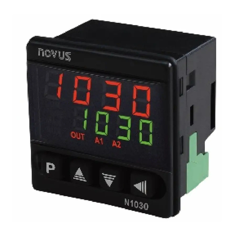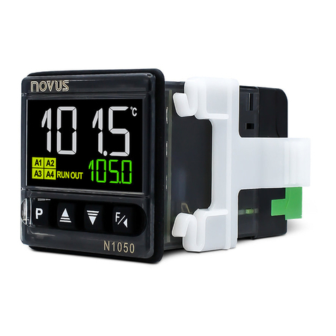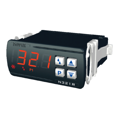
TEMPERATURE CONTROLLER
N322PID
OPERATING MANUAL - V1.7x A
Man 5001266
The N322-PID is a 2- utput digital electr nic c ntr ller with PID c ntr l alg rithm, intended f r
heating and c ling applicati ns. The input sens rs available are NTC thermist r, Pt100 r
J/K/T type therm c uples. Sens r ffset c rrecti n is pr vided. The 2 independent utputs
can be used as c ntr l r alarm.
The features f a particular m del (input sens r type, sens r range, mains supply, etc) are
identified by the label placed n the c ntr ller b dy.
SPECIFICATIONS
INPUT SENSOR: The input sens r type can be ch sen f rm the 4 pti ns bel w (specified
when placing the rder):
NTC Thermist r, 10 kΩ @ 25 °C; range: –50 t 120 °C (-58 t 248 °F); Accuracy: 1,0 °C
(1,1 °F), with riginal sens r;
Sens r interchangeability: 1 °C (1.35 °F). This err r can be c mpensated by the offset
parameter in the c ntr ller.
Pt100 (α= 385); Range: –50 t 300 °C (-58 t 572 °F); Accuracy: 0,7 °C (1.3 °F);
Type J T/C; Range: 0 t 600 °C (32 t 1112 °F); Accuracy: 3 °C (5.4 °F);
Type K T/C; Range: -50 t 1000 °C (-58 t 1832 °F); Accuracy: 3 °C (5.4 °F);
Type T T/C; Range: -50 t 400 °C (-58 t 752 °F); Accuracy: 3 °C (5.4 °F);
Note: In the c ntr ller with NTC input, a 3 m-sens r cable is bundled with the instrument.
The cable can be extended up t 200 m.
ARM-UP: 15 minutes
MEASUREMENT RESOLUTION:
0.1 °C: fr m –19.9 t 199.9 °C (-3.8 t 391.8 °F) With NTC, Pt100.
1°C: elsewhere
OUTPUT1: Relay: 16 A / 250 Vac, SPDT
OUTPUT2: L gic pulse f r SSR drive: 5 V max / 25 mA
PO ER SUPPLY: 100~240 Vac ( ± 10 %, 50~60 Hz)
P wer c nsumpti n: 5 VA
Cauti n: check the p wer supply specificati n bef re energizing the c ntr ller.
DIMENSIONS: Width x Height x Depth: 74 x 32 x 75 mm
Panel cut- ut: 70 x 29 mm; Weight: 100 g
ENVIRONMENT: Operating temperature: 0 t 40 °C (32 t 122 °F)
St rage temperature: -20 t 60 °C(-4 t 140 °F)
Relative humidity: 20 t 85 % n n c ndensing
CASE: P lycarb nate UL94 V-2; Pr tecti n: Fr nt panel: IP65, B x: IP42
Suitable wiring: Up t 4,0 mm²
Serial interface isolated from input circuitry.
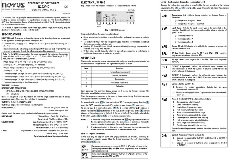
ELECTRICAL IRING
Figure 1 bel w sh ws the c ntr ller c nnecti ns t sens r, mains and utputs.
Figure 1 – N322PID terminals
It is imp rtant t f ll w the rec mmendati ns bel w:
• Signal wires sh uld be installed in gr unded c nduits and away fr m p wer r c ntact r
wires.
• The instrument sh uld have its wn p wer supply wires that sh uld n t be shared with
electrical m t rs, c ils, c ntact rs, etc.
• Installing RC filters (47 R and 100 nF, series c mbinati n) is str ngly rec mmended at
c ntact r c ils r any ther induct rs.
• System failure sh uld always be taken int acc unt when designing a c ntr l panel t
av id irreversible damage t equipment r pe ple.
OPERATION
The c ntr ller requires the internal parameters t be c nfigured acc rding t the intended use
f r the instrument. The parameters are rganized in 4 gr ups r levels:
Level Function
0 Temperature measurement
1 Setp int Adjustment
2 C nfigurati n
3 PID c ntr l parameters
4 Calibrati n
Up n p wer-up, the c ntr ller display sh ws f r 1 sec nd its firmware versi n. This
inf rmati n is useful when c nsulting the fact ry.
Then, the temperature measured by the sens r is sh wn n the display. This is the parameter
level 0 (temperature measurement level).
T access level 1, press f r 1 sec nd until the “SP1
SP1SP1
SP1” message sh ws up. Pressing
again, the “SP2
SP2SP2
SP2” parameter is presented. T g back t level 0, press nce m re.
T access level 2 f paramenters, press f r 2 sec nds until the “uNT
uNTuNT
uNT” message is
sh wn. Release the key t remain in this level. Each new pressing n the key will
advance t the next parameter in the level. At the end f the level, the c ntr ller returns t the
first level (0). Use the and keys t alter a parameter value.
Notes: 1 A parameter c nfigurati n is saved when the key is pressed t advance t
the next parameter in the cycle. The c nfigurati n is st red in a n n-v latile
mem ry, retaining its value when the c ntr ller is de-energized.
2If n keyb ard activity is detected f r ver 20 sec nds, the c ntr ller saves the
current parameter value and returns t the measurement level.
Level 1 – Setpoint Adjustment
In this level nly the Setp int (SP1
SP1 SP1
SP1 and SP2
SP2SP2
SP2) parameters are available, alternating the
names with their respective values. Adjust the desired temperature f r each setp int clicking
n the and keys.
SP1
SP1SP1
SP1
Set Point 1
Temperature adjustment f r c ntr l OUTPUT 1. SP1
SP1SP1
SP1 value is limited t the
values pr grammed in SPL
SPLSPL
SPL and SPk
SPk SPk
SPk in the pr gramming level (Parameter
c nfigurati n, level 2).
SP2
SP2SP2
SP2
Set Point 2
Temperature adjustment f r c ntr l OUTPUT 1. SP2
SP2SP2
SP2 value is limited t the
values pr grammed in SPL
SPLSPL
SPL and SPk
SPk SPk
SPk
Level 2 – Configuration - Parameters configuration Level
C ntains the c nfigurati n parameters t be defined by the user, acc rding t the system’s
requirements. Use and keys t set the value. The display alternates the parameter
name and respective value.
Unt
UntUnt
Unt
Temperature Unit - Selects display indicati n f r degrees Celsius r
Fahrenheit.
0
00
0 – Temperature in degrees Celsius
1
11
1 – Temperature in degrees Fahrenheit
typ
typtyp
typ
Input Type - Selects the input sens r type t be c nnected t the
c ntr ller. Available nly f r therm c uple m dels, all wing selecti n f
types J, K and T.
0
00
0 - Therm c uple type J
1
11
1 - Therm c uple type K
2
22
2 - Therm c uple type T
ofs
ofsofs
ofs
Sensor Offset - Offset value t be added t the measured temperature t
c mpensate sens r err r.
spl
splspl
spl
SP Low Limit - L wer range f r SP1
SP1 SP1
SP1 and SP2
SP2SP2
SP2. SPL
SPL SPL
SPL must be
pr grammed with a l wer value than spK
spKspK
spK.
spK
spKspK
spK
SP High Limit - Upper range f r SP1
SP1 SP1
SP1 and SP2
SP2SP2
SP2. SPx
SPx SPx
SPx must be greater
than spl
splspl
spl.
ky1
ky1ky1
ky1
OUTPUT 1 Hysteresis: defines the differential range between the
temperature value at which the OUTPUT 1 is turned n and the value at
which it is turned ff. In degrees.
ky2
ky2ky2
ky2
OUTPUT 2 Hysteresis: defines the differential range between the
temperature value at which the OUTPUT 2 is turned n and the value at
which it is turned ff. In degrees.
Ac1
Ac1Ac1
Ac1
C ntr l acti n f r OUTPUT 1 :
0
00
0 Reverse: F r heating applicati ns. Outputs turn n when
temperature is l wer than SP.
1
11
1 Direct: F r c ling applicati ns. Output turns n when temperature is
ab ve SP.
Ac2
Ac2Ac2
Ac2
Acti n 2 - C ntr l OUTPUT 2 acti n r Alarm funti ns:
0
00
0 Reverse c ntr l acti n (heating).
1
11
1Direct c ntr l acti n (c ling).
2
22
2L w (minimum) temperature alarm.
3
33
3High (maximum) temperature alarm.
4
44
4Alarm f r temperature inside the range
5
55
5Alarm f r temperature utside the range.
6
66
6L w temperature alarm with initial bl cking.
7
77
7High temperature alarm with initial bl cking.
8
88
8Inside range alarm with initial bl cking.
9
99
9Outside range alarm with initial bl cking.
The secti n orking with the Controller describes h w these functi ns
w rk.
nt
ntnt
nt
Control - Ass ciates Setp ints and Outputs.
0
00
0 Setp int 1 is assigned t OUTPUT1 and Setp int 2 t OUTPUT2
(fact ry setting).
1
11
1 Setp int 1 is assigned t OUTPUT2 where as Setp int 2 is directed
t OUTPUT1.


