N323TR
NOVUS AUTOMATION 5/5
7. WORKING WITH THE CONTROLLER
The controller switches the refrigeration output on or off to bring the
system temperature up to the value set in the Setpoint parameter.
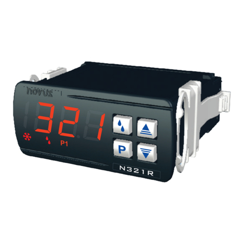
On the front panel, the flag lights up when the refrigeration output
is switched on.
7.1 DEFROST PROCESS
The DEFROST process aims to melt the ice accumulated on the
evaporator, making the refrigeration process more efficient.
The defrosting process occurs periodically and has a defined
duration. However, its execution can be prevented, and its end can
be anticipated depending on the temperature measured directly on
the evaporator. See dfs parameter.
Defrosting can occur by compressor stop, resistance heating, or by
reversing the compressor cycle:
•Defrost by compressor stop: At the start of the defrost
cycle, the refrigeration output will be switched off and the
evaporator will defrost naturally.
•Defrost by resistance heating: The defrosting output will
be used to connect an electric resistance that will heat the
evaporator to melt the accumulated ice. In this mode, the
refrigeration output will also be switched off.
•Defrost by reversing the compressor cycle: The
refrigeration output will not be switched off and the defrost
output will be used to reverse the compressor cycle.
During defrost, the indicated room temperature can be prevented
from being updated, depending on what is programmed in the dfh
parameter.
The dfi and dft parameters define, respectively, the interval
between one defrost and another and the duration of the defrost. On
the front panel of the controller, the flag will light up when the
controller is in the defrosting process.
Manual defrost: The key allows you to start or stop defrosting
immediately. By pressing this key for 3 seconds, the controller will be
forced into defrost. If it is in defrosting process, its end will be forced.
Defining the evaporator temperature at the end of defrosting:
1. Wait for ice to form in the evaporator.
2. Trigger a manual defrost.
3. Visually monitor the evaporator until all the ice has
disappeared.
4. Check the temperature measured by sensor 2 at that
moment (short press on ). This is the value used in the
End Defrost Temperature parameter dfs.
8. CONFIGURATION PROTECTION
The configuration protection system prevents undue changes to the
parameters of the controller and, consequently, its operating mode.
This system is composed of parameters that define the degree of
protection to be adopted (full or partial).
Protection is defined by the following parameters:
Parameter to enter a password that will allow you to
change other parameters.
Allows you to set the parameter levels to be protected:
1. Only Calibration
level is protected (factory
configuration).
2. Calibration and Configuration levels are protected.
3. All levels are protected (Calibration, Configuration,
and SP).
Allows to change the current password. You can set the
password to a number between 1 and 999.
8.1 CONFIGURATION PROTECTION OPERATION
The PAS parameter appears at the beginning of the protected level.
If you enter the password correctly, it is possible to change the
parameters of the protected levels.
If you do not enter the password correctly or simply pass by this
parameter, the parameters of the protected levels can only be
viewed.
Important notes:
1. When you enter an incorrect password 5 consecutive times,
the equipment will prevent new attempts for 10 minutes.
If you do not remember the current password, you can enter a
master password, which only allows you to set a new
password.
2. The equipment leaves the factory with password 111.
9. MASTER PASSWORD
The master password, which allows you to set a new password for
the controller, uses the serial number of the equipment. It is
composed as follows:
[ 1 ] + [ largest number of SN2 ] + [ largest number of SN1 ] +
[ largest number of SN0 ]
The master password for an equipment with serial number 97123465
is: 1936
Example: 1 + sn2 = 97; sn1 = 123; sn0 = 465 = 1 + 9 + 3 + 6
9.1 HOW TO USE YOUR MASTER PASSWORD
1. In the Pas parameter, enter the master password.
2. In the PAC parameter, enter any new non-zero (0) password.
3. Use the new password.
10. ERROR INDICATION
On the display, the controller shows messages that correspond to
problems related to temperature measurement.
Whenever they are displayed, the control output relay will be turned
off immediately.
The measured temperature has exceeded the upper
limit of the sensor measurement range.
NTC sensor short-circuited.
The measured temperature has exceeded the lower
limit of the sensor measurement range.
Broken NTC sensor.
Table 2 –Error indications
11. WARRANTY
Warranty conditions are available on our website
www.novusautomation.com/warranty.


