NSS Opti-Mist 20B User manual

OPERATION MANUAL
Opti-Mist™20B
Wide Area Sprayer

NSS Chemical Use Disclaimer
WARNING: Chemical use hazard.
Each chemical, such as a disinfectant, has a unique set of hazards and needs to be handled
properly to ensure worker safety.
Read and understand the chemical product’s SDS and label prior to use.
Be aware of rst aid procedures related to the product in use.
It is a violation of Federal law to use a chemical in a manner inconsistent with its label.
If using a disinfectant, be sure to follow the chemical manufacturer’s instructions regarding
dilution, coverage and dwell time.
Use personal protective equipment as detailed by the chemical product’s SDS. Excessive
exposure to disinfectants and other types of chemicals might be harmful to one’s health.
For use with non-ammable, non-combustible and non-volatile uids only. Never spray a
ammable chemical (ash point less than 60˚C).
Ensure the area being sprayed has proper ventilation.
To dispose of chemical products, refer to product labels.

ALL REPAIR SERVICE MUST BE PERFORMED BY AN NSS AUTHORIZED DISTRIBUTOR /
SERVICE STATION USING ONLY NSS ORIGINAL EQUIPMENT PARTS.
SAVE THESE INSTRUCTIONS
IMPORTANT SAFETY INSTRUCTIONS
WARNING: Failure to observe these instructions can cause
Personal injury to machine operator or bystanders.
INTENDED USE
This machine is intended for commercial spraying
applications. NSS does not recommend using this
machine for any other purpose.
FOR SAFETY:
• ALWAYS read and understand all instructions
before operating or servicing machine.
• ALWAYS use this machine ONLY as described in
this manual.
• NEVER attempt to operate this machine unless
you have been trained in its operation.
• NEVER allow an untrained person to operate this
machine.
• NEVER attempt to operate this machine if it is not
working properly or has been damaged in any
manner.
• ALWAYS wear eye protection, gloves, long sleeve
shirt, long pants, and full foot protection when
spraying.
• NEVER disconnect or modify any switches or
safety devices.
• NEVER park the machine on an incline or decline.
Machine may roll away if not attended.
• NEVER spray this machine with water or any
liquids.
• NEVER allow the battery charging plug to get wet
or a short may occur.
• NEVER allow this machine to be used as a toy.
Close attention is necessary when used by or near
children.
• ALWAYS wear clean tennis shoes or “non-slip”
shoes. Leather soled shoes will become extremely
slippery when wet.
• NEVER allow this machine to freeze.
• NEVER expose the machine to rain, snow, or
extreme temperatures.
• NEVER leave a pressurized machine in the (hot)
sun. Heat can cause a pressure build-up resulting
in possible explosion.
• NEVER store any items on this machine.
• ALWAYS store this machine indoors in a dry, cool
area.
• ALWAYS deploy “WET FLOOR” cones and other
safety equipment when using this product. Failure to
do so could create a Slip & Fall hazard.
WARNING: Do not spray ammable gases or liquids,
undiluted acids or solvents. This includes gasoline,
thinning agents or hot oil that can form an explosive
mixture when mixed with air. Do not use with acetone,
undiluted acids or solvents.
WARNING: This product can expose you to chemicals including Lead and Lead
Compounds which is know to the State of California to cause cancer,
birth defects, or other reproductive harm.
For more information go to www.P65warnings.ca.gov

IMPORTANT SAFETY INSTRUCTIONS
BATTERY POWERED EQUIPMENT
WARNING:Failure to observe these instructions can cause personal
Injury to machine operator or bystanders.
Read and understand
all instructions before
installing or charging
batteries.
No smoking, open
ames, or sparks while
working with batteries.
Contains acid.
Avoid contact
Poison. Causes
severe burns.
Avoid contact.
Shock or
electrocution
hazard.
WARNING: Batteries emit hydrogen, which can cause re or explosion.
NEVER smoke, light a match, or cause a spark during operation or charging.
ALWAYS charge in a well-ventilated area away from open ame.
GENERAL
•ALWAYS read and understand all instructions before
installing or charging batteries.
• NEVER attempt to install or charge batteries unless you
have been trained to do so.
• NEVER allow an untrained person to install or charge
batteries.
• ALWAYS remove all jewelry when working on or near the
batteries.
• ALWAYS turn o all switches during installation and
service.
• ALWAYS disconnect the battery leads before performing
any service or repair.
• ALWAYS wear eye protection and protective clothing to
avoid contact with battery acid.
• NEVER incinerate the battery even if it’s severely
damaged or worn out. The battery can explode in a re.
Toxic fumes and materials are created when the battery is
burned.
•IF CONTACT WITH BATTERY CONTENTS OCCURS,
follow these instructions:
• SKIN – rinse area with mild soap and water.
• EYES – Flush with water for 15 minutes or until
irritation ceases.
• INTERNAL – Drink water or milk. Follow with Milk
of Magnesia, beaten egg or vegetable oil. Call a
physician immediately.
• Contents of opened battery cells may cause
respiratory irritation. Provide fresh air. Seek
medical attention if the symptoms persist.
• NEVER lay anything on top of batteries as arcing may
occur.
• ALWAYS use the battery charger provided with this
machine which is specically designed to the charge
its 24V AGM battery system.
• NEVER splash or immerse the battery with water or
any other liquid.
• NEVER store the or use the machine and battery
where the temperature exceeds 105°F (40°C).
• NEVER use a battery that has a cracked case or is
damaged in any way. Damaged batteries should be
returned to a service center for recycling.
• NEVER allow metal objects to touch the exposed
battery terminals.
• NEVER store battery with places with loose metal
objects.
• ALWAYS properly protect battery from short circuit if
transporting for commerce or on airplanes.
BATTERY INSTALLATION
• ALWAYS use only the two 12V AGM batteries
designed for this machine.
BATTERY CHARGING
• ALWAYS read instructions on charger carefully.
• ALWAYS use the NSS supplied charger with proper
voltage rating.
• ALWAYS recharge the batteries after each use, leave
the charger plugged into the wall outlet when the
machine is not in use.
• ALWAYS recharge the battery until the green LED on
the battery is lit.
ALL REPAIR SERVICE MUST BE PERFORMED BY AN NSS AUTHORIZED DISTRIBUTOR /
SERVICE STATION USING ONLY NSS ORIGINAL EQUIPMENT PARTS.
SAVE THESE INSTRUCTIONS

Marking #1
Marking #2
Marking #3
Marking #4
Marking #5
IMPORTANT SAFETY INSTRUCTIONS
WARNING: Read these original
instructions prior to initial use of the
appliance/machine.
Safety Instructions:
Safety Equipment
This appliance is equipped with devices to protect the user, and
must not be rendered inoperable or bypassed.
Symbols used in these instructions
DANGER – Immediate danger that can cause
severe injury or even death.
WARNING – Possible hazard that could lead to severe
injury or event death.
CAUTION – Possible hazard that could lead to mild
injury or damage to property.
Electrical shock hazard.
Read the Operator Manual.
No smoking, open ames, or sparks near the
batteries.
Batteries - acid and hydrogen gas.
Poison. Causes severe burns. Avoid contact.
Recycle packaging.
Dispose of equipment through suitable collection
systems.
Markings
Below are descriptions of the various marking used on the
Op[ti-Mist 20B:
#1 This product may contain a chemical known to the
state of California to cause cancer, or birth defects or other
reproductive harm
#2 Control Panel - Power switch.
#3 Control Panel - 10 Amp Breaker
#4 Control Panel - Pump Control. Turn clockwise to
increase pump pressure, turn counter-clockwise to
decrease pump pressure.
#5 Control Panel - Side Sprayer switch. Turn on to
activate the side spraying attachments.

GROUNDING OF ELECTRICAL
EQUIPMENT - BATTERY CHARGER
WARNING: Improper connection of the
equipment–grounding conductor can result in a risk
of electric shock. Check with a qualied electrician or
service person if you are in doubt as to whether the
outlet is properly grounded. Do not modify the plug
provided with the charger. If outlet is not suitable for
safe use; have a properly grounded outlet installed by
a qualied electrician.
North America: Always use a properly grounded 3-wire
extension cord, which has male and female plugs. If
25 foot [7.6m] extension cords are used, the electrical
carrying capacity should be no less than 14-3 ST, 50
foot [15.2m] extension cords no less than 12-3 ST.
Grounding Instructions
This charger shall be grounded while in use to protect
the operator from electric shock. The charger is
provided with a three-conductor cord and a three-
contact grounding type attachment plug. The plug
must be plugged into an appropriate outlet that is
properly installed and grounded in accordance with all
local codes and ordinances. The green conductor in
the cord is the ground wire. Never connect this wire to
other than the grounding pin of the attachment plug.
If the cord provided with the charger has an attachment
plug as shown in Figure A. below, it is intended for use
on a nominal, 120-volt circuit. If a properly grounded
receptacle as shown in Figure A is not available, an
adapter may be installed as shown in Figure B if the
outlet box that houses the receptacle is grounded. Be
sure to fasten the grounding tab (the green colored
rigid ear, lug or the like extending from the adapter)
with a metal faceplate screw.
If the cord provided with the charger has an attachment
plug as shown in Figure C, it is intended for use on a
nominal 240-volt circuit (single phase only). Changes
to the attachment plug or use of adapters to other
plug types must be done in accordance with local
regulations.
NOTE: In Canada, the use of a temporary adapter is not
permitted by Canadian electrical code, C22.1.
FIGURE A
FIGURE B

Machine Inspection
1. Now that the machine is unpacked, remember to
recycle all the packing materials.
2. Inspect the machine for damage or missing
components. If damage is found, contact the local
freight company to le a claim.
• Located in the far left side of the control panel is the
Power Switch. The toggle switch is in the “OFF”
position when it is down and is in the “ON” position
when it is up. When turned on, the pump will turn on
and pressurize the system. Note: the Power Switch
will not work unless the Circuit Breaker is in the reset
(lower, locked) position.
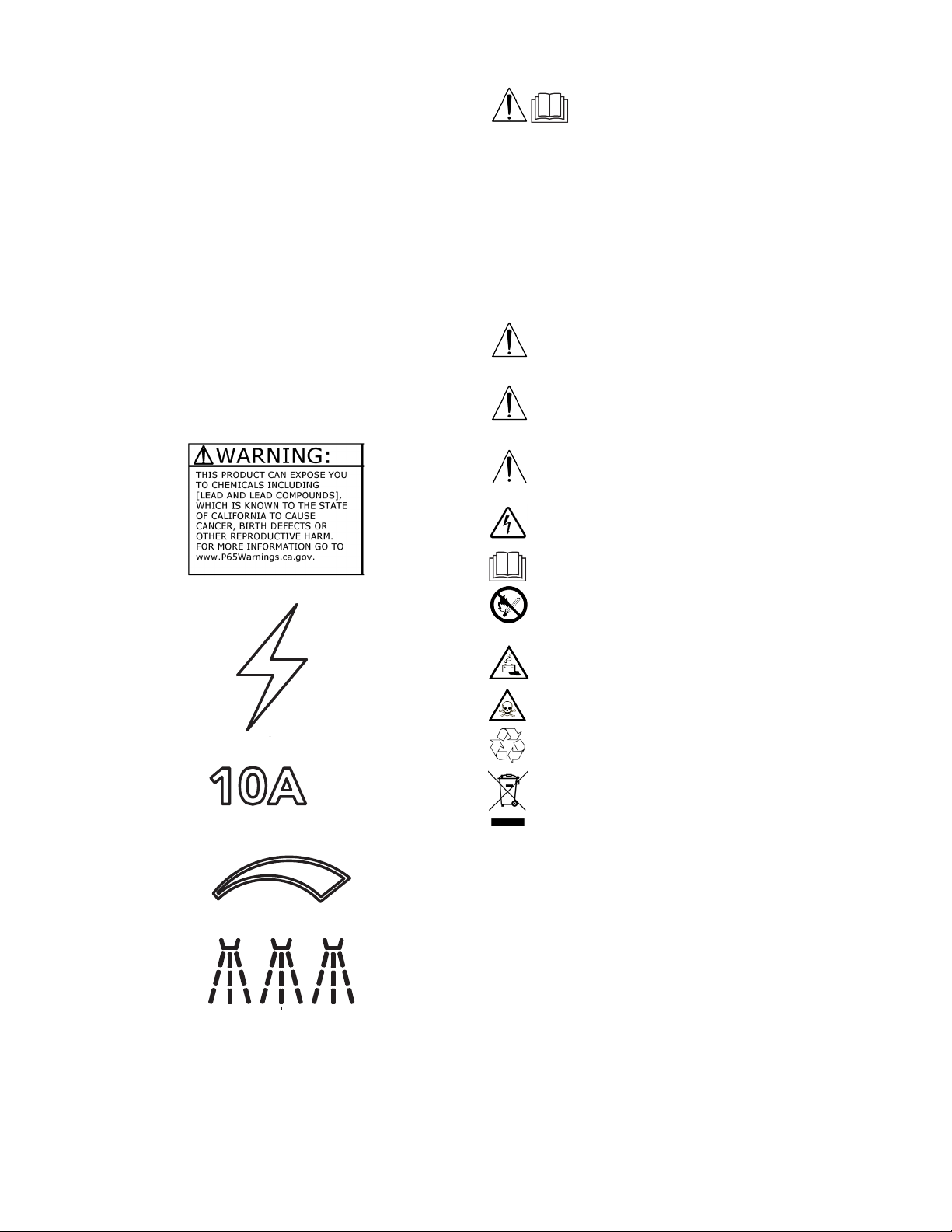
• Located next to the Power Switch is the Circuit
Breaker The circuit breaker is rated for 10 amps.
The machine is shipped with the circuit breaker in the
“Disconnected” or tripped position. The circuit breaker
is reset by depressing the plunger until is click in to the
lower, locked position.
• The Battery Meter is located in the center of the
control panel. The battery meter is a 10 segment LED
display. When fully charged, the right most LED will
be illuminated. As the battery discharges, the LED
will move to the left indicating a 10% lower amount of
battery charge. When the battery is 70% discharged
the 2nd LED segment from the left will be ashing.
When the battery is 80% discharged, the two left most
LEDs will ash. See the section on Battery Charging
for further instructions.
• Pump Pressure Control is to the right of the Battery
Meter. The pump pressure control varies the speed of
the pump. This will decrease or increase the pressure
and ow of the pump. To decrease the pressure/
ow, turn the control knob counter clockwise. To
increase the pump pressure/ow, turn the control knob
clockwise.
• Spray Bar Switch is located on the right-hand side
of the control panel. To turn the spray bars on, ip this
switch to the “UP” position. Note: The spray bars will
not work unless the Power Switch is “On”, powering
the pump.
Solution Pump - The solution pump is a self-priming 60
PSI pump. It has a pressure switch that will shut o when
the pressure reaches 60 psi. The pump will turn back on
when the pressure drops below 45 psi.
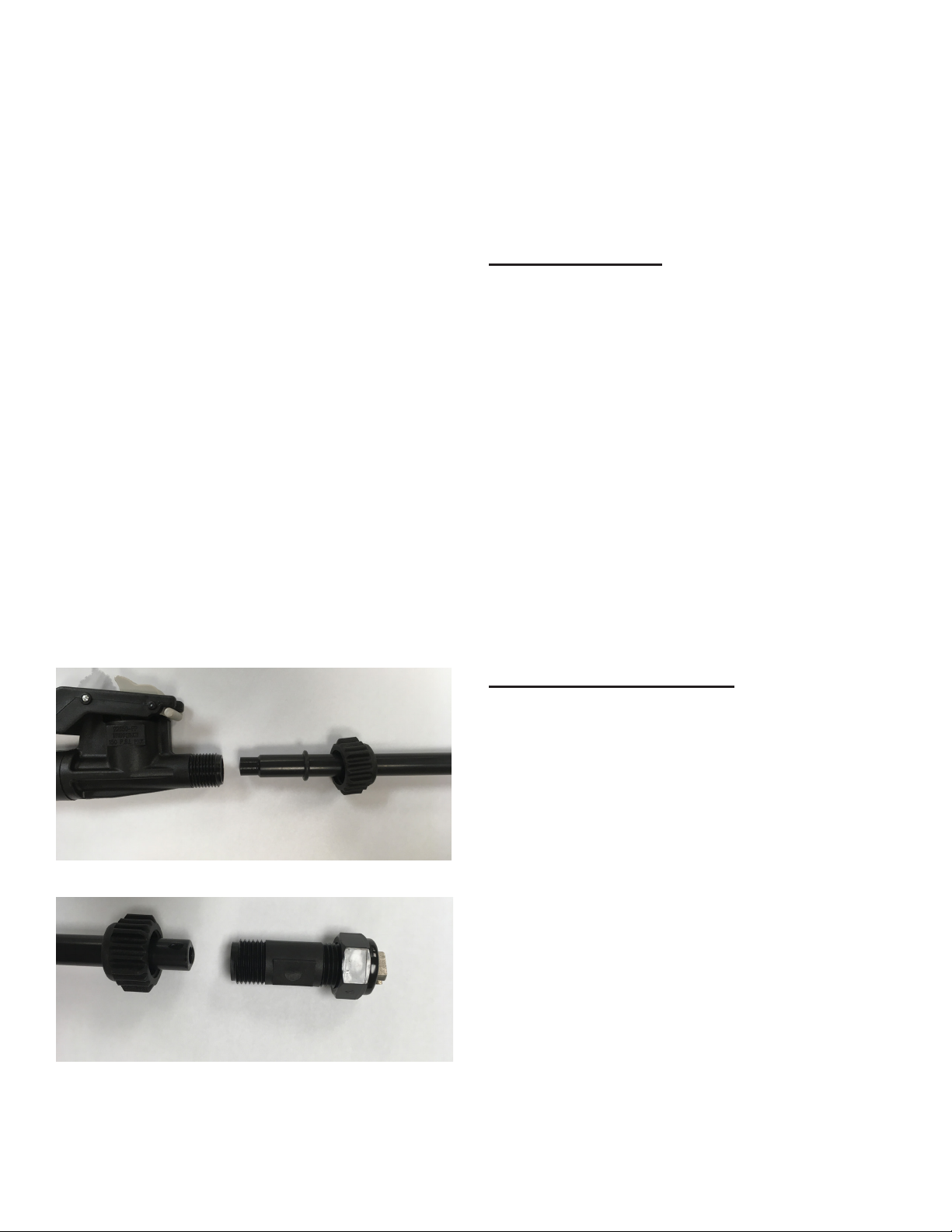
In-Line Screen - The solution pump is protected from
debris that may enter the solution tank by an in-line lter
screen. The solution screen is located under the machine
near the back. There is a ball valve just ahead of the In-
line screen. To clean the screen, shut the ball valve and
unscrew the clear plastic sight glass. The screen can be
removed and rinsed under running water. Replace the
screen and re-install the sight glass. Open the ball valve to
allow water to ow from the solution tank to the pump.
Center Spray Bar - The center spray bar contains two
spray tips that spray in an overlapping fan shape. Each tip
will ow 0.1 GPM of solution when the pump is at 40 PSI
running pressure (nominal.) To turn on the Center Spray
Bar, turn on the Power Switch and the Spray bar Switch.
Unpacking Instructions
1. Carefully cut the two (2) bands from around the carton.
2. Remove the staples and open the top aps.
3. Remove the staples from the bottom of the carton
attached to the pallet.
4. Remove the carton.
5. Locate the small box under the machine, remove from
the pallet and set aside.
6. One at a time, unbolt the front axle bolt and remove
the lag screws holding the pallet mounting bracket.
Reinstall the rst axle bolt before working on the
second side. -This will free the machine from the
pallet.
7. Locate the rear of the machine where the handle is
located.
8. Use the handle to back the machine o the pallet,
lifting the caster wheels o the pallet and setting them
on the oor.
9. Once the caster wheels are on the oor, press down
to pivot the machine’s weight onto the caster wheels,
lifting the 10” wheels o the pallet.
10. Back the machine up until the 10” wheels are clear of
the pallet. Set all the wheels on the ground.
11. Remove and read all operation instructions.
12. Switch the circuit breaker to the “ON” position on the
control panel.
13. Recycle the carton and pallet.
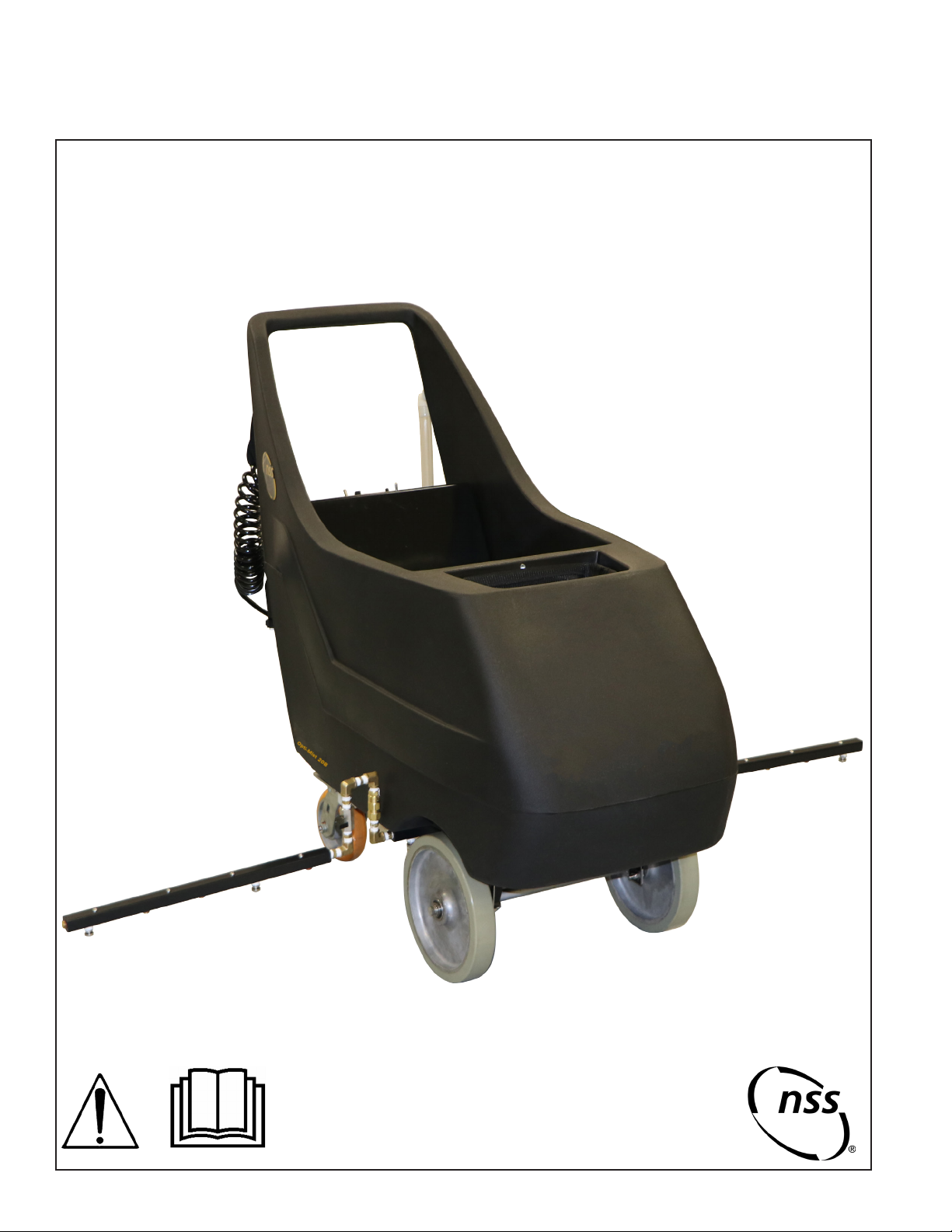
Intended Use
The Opti-Mist 20B is intended for commercial use, for
spraying of liquid solutions on level oors in an indoor
environment, for example in hotels, schools, hospitals,
factories, shops, oces and retail businesses. The
spraying settings can be adjusted to suit the spraying task.
Water quantity, pump pressure, walking speed and solution
concentration can be adjusted by the user.
Machine Components
Solution Tank - The solution tank is the plastic tank body.
It has a capacity of 20 gallons (75 liters.)
Control Panel - The operator control panel is located at
the upper rear area of the machine. Operator controls are
positioned for ease of use, and include icons for simplied
user training. This panel has components that control
various machine functions:

Side Spray Bars - The Side Spray Bars are attached to
the outboard ends of the Center spray bar with a swivel
attachment. The side spray bars can be turned o by closing
the 1/4 turn ball valves that are in-line upstream of the side
spray bars.
To activate the side spray bars, turn on the Power switch
and the Spray bar switch. Also ensure that the ball valve
leading to the side spray bar is open.
Solution Gage Hose - The amount of uid in the tank is
visible via the clear hose at the back left of the machine. As
you spray, keep an eye on the liquid level, rell as needed.
The vinyl tube can be used to drain the tank by pulling down
on the hose from the top.
Spray Wand Attachment - The Spray Wand attachment is
connected via a quick connect tting. To remove the spray
wand simply disconnect the quick connect tting. To spray
solution with the wand, point the tube end in the direction
you want to spray and squeeze the wand handle. As long as
the Power Switch is in the “ON” position, solution will ow to
the tip.
Preparing the Machine
Installing the Spray Wand:
If not already attached, connect the wand extension tube
and tip as follows:
1. Remove the spray wand from the small cardboard
shipping box.
2. Connect the wand assembly to the wand handle as
shown:
3. Connect the spray nozzle to the wand assembly.
4. Plug the quick connect on the end of the hose into the
mating quick connect in the basket area.
5. Fill the solution tank with the appropriate amount
of water and mix any solution per the solution
manufacturer’s instructions.
Machine Operation
The machine is designed to enable a plurality of spraying
options. The various options include:
1. Spray wand only,
2. Center Spray Bar only,
3. Center Spray bar and either or both side spray bars.
4. Spray wand at the same time as any combination of
spray bars.
To use the Spray wand:
1. Plug the spray wand quick connect into the mating
quick connect adapter in the center basket area of the
machine.
2. Ensure the two halves of the spray wand are securely
connected. Hand tightening is recommended for
plastic nut connections.
3. Inspect the spray wand end to ensure the spray tip
is installed and oriented in the direction you want to
spray.
4. Turn the Power Switch to the “ON” position. Ensure the
Battery Meter shows One bar and that there is ample
battery charge.
5. Point the wand tube end in the direction you want to
spray and squeeze the wand handle.
6. Increase / Decrease the pump pressure by dialing
up or down the Pump Pressure Control knob. Select
a pressure where the pump runs constantly, and is
not repeatedly activating the shuto switch. This will
ensure constant pressure and even ow of solution.
To use the Center spray bar only:
1. Turn the ball valves leading to the side spray bars to
the “OFF” position.
2. Turn the Power Switch to the “ON” position. Ensure the
Battery Meter shows One bar and that there is ample
battery charge.
3. Turn the Spray Bar Switch to the “ON” position. Any air
in the spray bar will purge out and the spray tips will
begin to spray the solution.
4. Ensure there is a uniform, consistent pattern coming
from the spray tips. If one or more of the tips is not
spraying a uniform, consistent fan shape, turn o the
Spray Bar switch and clean the tip. (Refer to the “Tip
Cleaning” section below.)
5. Once the tips are spraying properly, begin to move the
machine forward to start spraying solution onto the
surface.
6. When complete, turn the Spray bar switch to the “OFF”
position and conrm the spraying has stopped.
NOTE: There will be some leakage from the spray tips as
the uid in the spray bars drips out. Either collect the drips
with cups or other containers, or allow it to drip onto a
surface that will not be aected.

To use the Center spray bar and the side spray bars:
1. Turn the ball valves leading to the side spray bars to
the “ON” position.
2. Extend the side spray bars to the desired position.
3. Turn the Power Switch to the “ON” position. Ensure the
Battery Meter shows One bar and that there is ample
battery charge.
4. Turn the Spray Bar Switch to the “ON” position. Any air
in the spray bar will purge out and the spray tips will
begin to spray the solution.
5. Ensure there is a uniform, consistent pattern coming
from the spray tips. If one or more of the tips is not
spraying a uniform, consistent fan shape, turn o the
Spray Bar switch and clean the tip. (Refer to the “Tip
Cleaning” section below.)
6. Once the tips are spraying properly, begin to move the
machine forward to start spraying solution onto the
surface.
7. When complete, turn the Spray bar switch to the “OFF”
position and conrm the spraying has stopped.
NOTE: There will be some leakage from the spray tips as
the uid in the spray bars drips out. Either collect the drips
with cups or other containers, or allow it to drip onto a
surface that will not be aected.
Machine Maintenance
Routine maintenance is critical to ensure proper machine
operation and spraying performance. Perform all
maintenance procedures as follows:
Always turn OFF all machine switches before
performing any maintenance.
Daily maintenance
At the end of the day empty all liquid from the solution
tanks.
• Rinse the tank with clean water to remove debris and
prevent solution residue build up, to prevent odors
from building up.
• Run clean water through both the Wand spray tip and
the center and side spray bars to purge them of any
remaining solution.
• The solution tank can be emptied by removing the
solution gage hose and allowing the unit to drain
• Remove the spray tips (1/4 turn) from the spray bars
and put them in a glass or plastic container with a
solution of 25% vinegar and water overnight to remove
any solution residue.
• Remove the spray tip from the wand by unscrewing
the hex nut holding it in place. Place the tip in a glass
or plastic container with a solution of 25% vinegar and
water overnight to remove any solution residue.
• Clean the 100 mesh screen that is installed in the
wand by rinsing it in running water. Then place it in
the vinegar solution with the tip overnight.
• Rinse the caster wheels and the 10” wheels to clean
them of any solution that remains on the surface.
Weekly Maintenance (25 Hours)
• Verify all daily maintenance has been performed.
• Flush clean solution tank, hoses and spray bars with a
mixture of 8 ounces (250 milliliters) white vinegar to one-
gallon (4 liter) warm water.
• Pour it into the solution tank, turn the machine “ON” and
operate it to completely clean the tank, and the spray jets,
(running for 30 seconds should be sucient). This will
remove any chemical residue. Failure to ush the solution
system will result in poor spray patterns and corroded jet
spray tips.
• Remove and clean the ne mesh lter in the bottom
of the solution tank. This lter is mounted externally
under the solution tank (body). First close the ball valve
located just ahead of the clear plastic canister. Remove
the screen after removing the canister. Twist the canister
to remove Remove the lter mesh screen to rinse out.
Replace when completed.
CAUTION If there is any clean solution in the tank it
will drain out at this time. Reassemble and check for
leaks.
• Repair or replace any worn or damaged components
as needed.
Battery Charging
When the machine is supplied with batteries installed, the
battery charger is set by the NSS factory for the installed
batteries.
DANGER: Charge the batteries in a well ventilated area.
Warning - For information and warning about the
battery and the battery charger, follow what is
described in the battery charger manual enclosed
with this document.
Warning - When replacing NSS supplied batteries, or
installing batteries purchased from another source,
the battery charger must be set to the correct curve
andchargecurrentforthespecicbatterytype.
Do not throw batteries in the regular waste.
Charging procedure:
• Move the machine to the vicinity of a main
electrical outlet.
• Unwind the cable and connect it to the outlet.
• Leave the batteries to charge until the “Green”
LED comes on, then remove the power cable and
wind it up on the cord wrap bracket.
Battery Charging Time Chart
Battery Size Charge Time
35AH 15 hr

TROUBLESHOOTING
Symptom Cause Solution
No Solution From Spray
Tips
Spray nozzle tips plugged. Disassemble and clean.
Solution tank empty. Rell tank.
Pump failed. Repair or replace as required.
Defective pump seal. Replace pump.
Uneven Spray Nozzle
Pattern.
Spray nozzle tips plugged. Clean or replace.
Worn solution pump. Repair or replace as required.
Solenoid valve clogged. Bleed air lock from system.
No Solution From Spray
Tips On Accessory Wand.
Spray nozzle tips plugged. Remove nozzles and clean.
Incorrect spray nozzles. Install correct spray nozzles.
Solution tank empty. Rell.
Pump failed. Repair or replace as required.
Defective pump seal. Replace pump.
Kinked solution hose. Straighten hose.
Quick connect disconnected. Reconnect tting onto machine.
Pump Runs But Has Little
Or No Output.
Internal pump parts worn. Rebuild pump head or replace.
Solenoid valve will not open. Replace solenoid valve.
Solution tank lter plugged. Remove obstacle or replace.
Pump Motor Will Not Run. Motor shorted out. Replace motor.
Faulty pressure switch. Replace pressure switch.
Faulty pump switch / wiring. Repair or replace.
Batteries Will Not Charge Faulty charger cord or charger Replace battery charger
Improper charging has lead to
damaged batteries that won’t hold
charge
Replace batteries, follow the
instructions on proper charging of
batteries.
Machine Will Not Turn On Circuit Breaker in the “Tripped”
position.
Press the circuit breaker and click
it into it’s lower, locked position.
Battery charger is charging the bat-
teries - Locked out.
Wait until the charging process
has completed, unplug the char-
ger from the electrical outlet.
Side Sprayers Have
Rotated and Don’t Spray
Down
Locknut on the side has loosened
allowing the side spray bars to
move.
Reposition the spray bars to the
original orientation and tighten the
lock nut to the Center Spray bar
with a wrench.

GENERAL INFORMATION AND WARNINGS
• This NSS machine is are delivered with the
SPE CBHD1 24-5 battery charger set for
35AH AGM batteries.
• Electronic automatic battery charger with
microprocessor suitable for diernt battery
types. See Battery charger manual included
with this machine for details.
• Fully automatic charging cycle with electronic
settings; protected against overload, short-cir-
cuit at clamps and reversed polarity.
• Before starting to charge, make sure the
voltage of the equipment suits the voltage of
the battery, that the charging current suits the
capacity of the battery and that the select-
ed charging curve (for lead-acid batteries or
airtight gel batteries) is correct for the type of
battery to be charged. In addition, make sure
the rated input voltage of the charger suits
the available supply voltage and the system
is equipped with grounding.
• Pay attention to any remarks of the battery
manufacturer.
OPERATING PRINCIPAL OF THE CBHD1 24-5
When powering up the battery charger it will
display either the ashing Red LED or Green
LED for 5 seconds while it checks the AC input
voltage and the DC battery voltage and decide
whether or not to start the charging process.
Flashing Red LED at start up indicates one of the
two WET charging curves.
Flashing Green LED at start up indicates one of
the two AGM/GEL charging curves.
If the battery is not connected to the battery
charger or if there is an anomaly, the Yellow LED
will ash. If the result is positive after 1 second,
the charging of the battery will start with the Red
LED on. The output relay closes and the cur-
rent of the rst phase rises slowly until the pro-
grammed nominal value is reached.
If the user disconnects the battery from the
battery charger during charging, the Red, Yellow
and Green LED’s will be on for 1 second. After
that, the battery charger will reset.
The progress of the charging process is shown
by three LED’s: Red, Yellow and Green as typical
for the battery charger product range. The Green
LED indicates the end of the charging or the last
phase in the case of a deep charging process.
When charging is nished, the relay is opened to
disconnect.
OPERATION INSTRUCTIONS
• Plug the cord into a socket.
• The charging cycle progress will be shown by
Red, Yellow and Green LED indicators. At the
end of the charge, when the green indicator
is on, unplug the cord from the socket and
operate the machine.
Battery Charger Operating Instructions – SPE CBHD1 24-5
Front label on Battery Charger SPE CBHD1-XR-P
Red LED Yellow LED Green LED

REPLACEMENT PARTS
PART NO DESCRIPTION
4993131 Spray Body & Tip (Spray Bars)
4993459 Wand & Hose Assembly
The below are included in 4993459 Wand & Hose Assembly
4993151 Trigger Jet Sprayer Handle
4993161 Wand-15” Polypropylene
4993171 Spray Tip (Spray Wand)
4993181 Front End Adapter
4993191 Tip Retainer Nut
4993281 25FT Black Spray Gun Hose
w/ Female Quick Connect
4993611 Filter - In-line Strainer - 100
ALWAYS USE GENUINE NSS REPLACEMENT PARTS
NSS ® Enterprises, Inc.
3115 Frenchmens Road
Toledo, Ohio 43607
PHONE (419) 531-2121
FAX (419) 531-3761
www.nss.com
Opti-Mist™ 20B Wide Area Sprayer Rev Orig 07-20 9094946
Table of contents
Other NSS Paint Sprayer manuals