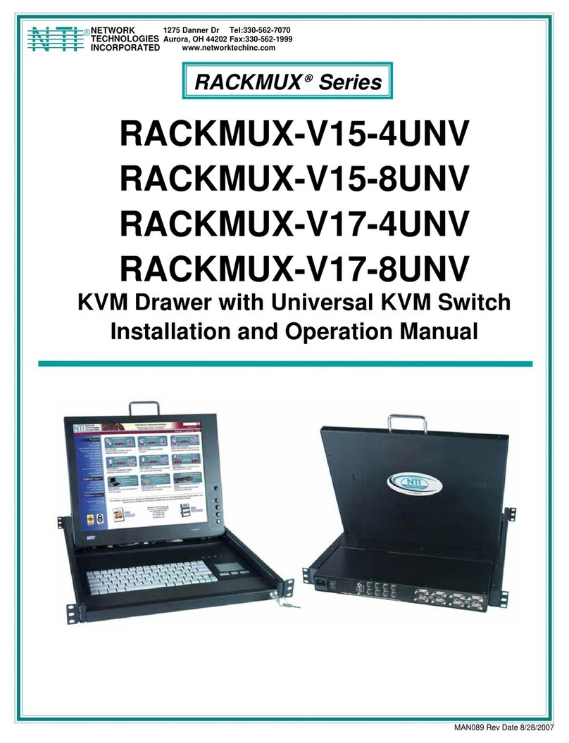
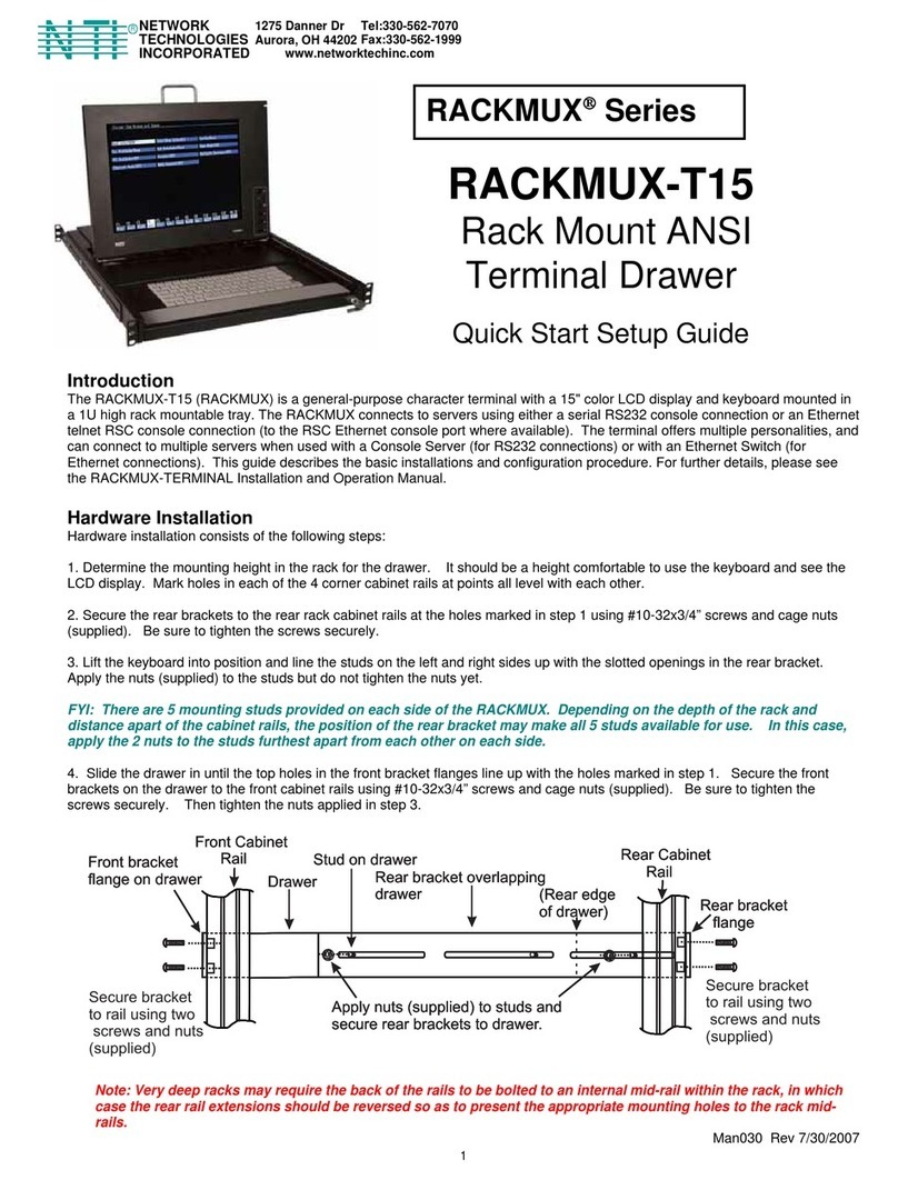
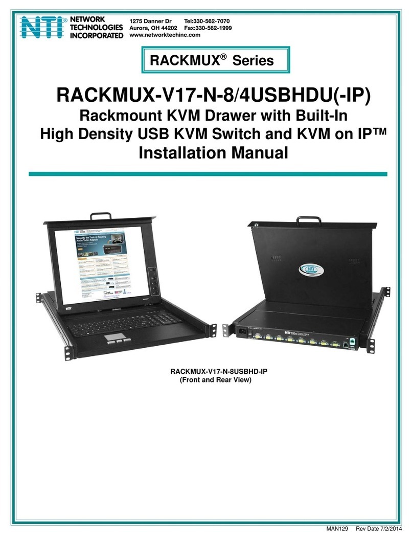
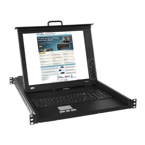
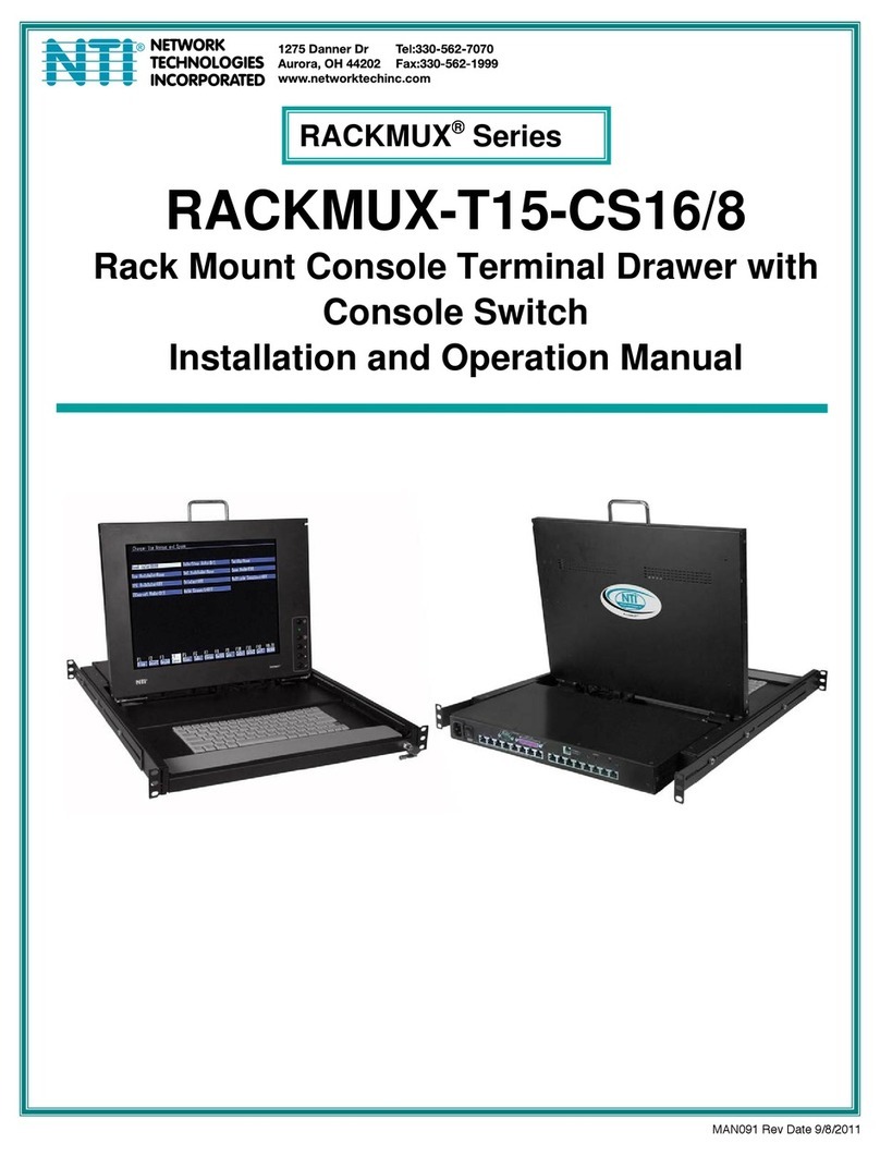
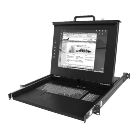
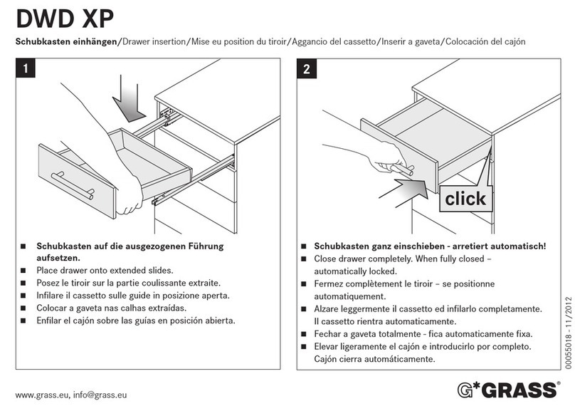
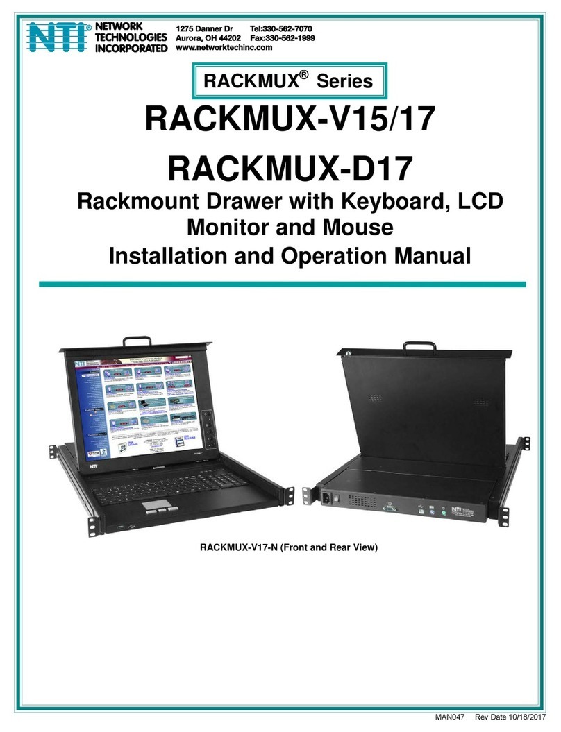
NTI RACKMUX Series User manual

RACKMUX-4K17-N-xHD4K
Rackmount KVM Drawer with Built-In
4K Video USB KVM Switch
Installation Manual
MAN324 Rev Date 12/13/2018
RACKMUX®Series
RACKMUX-4K17-
N
-16HD4K
(Front and Rear View)

i
TRADEMARK
RACKMUX is a registered trademark of Network Technologies Inc in the U.S. and other countries.
COPYRIGHT
Copyright © 2011, 2018 by Network Technologies Inc. All rights reserved. No part of this publication may be reproduced, stored
in a retrieval system, or transmitted, in any form or by any means, electronic, mechanical, photocopying, recording, or otherwise,
without the prior written consent of Network Technologies Inc, 1275 Danner Drive, Aurora, Ohio 44202.
CHANGES
The material in this guide is for information only and is subject to change without notice. Network Technologies Inc reserves the
right to make changes in the product design without reservation and without notification to its users.

ii
TABLE OF CONTENTS
Introduction......................................................................................................................................................................1
Materials Included:....................................................................................................................................................1
Material Not Supplied, but may need to be ordered................................................................................................1
RACKMUX Single-Person Installation ............................................................................................................................2
Cable Connections..........................................................................................................................................................6
Connect Video Sources...............................................................................................................................................6
Terminal Connection for RS232 ..................................................................................................................................7
Connect Extra Device..................................................................................................................................................7
Features and Functions...................................................................................................................................................8
Control Methods..............................................................................................................................................................9
Command Mode .......................................................................................................................................................9
Keyboard Control.........................................................................................................................................................9
USER ACCESS FUNCTIONS.......................................................................................................................................10
Command Mode........................................................................................................................................................10
Navigation...............................................................................................................................................................10
Settings Menu.........................................................................................................................................................11
Broadcast Mode......................................................................................................................................................12
Scan Mode..............................................................................................................................................................13
Normal Mode ..........................................................................................................................................................14
Administrator Settings.............................................................................................................................................15
Port Name List........................................................................................................................................................16
RS232 CONTROL.........................................................................................................................................................17
RS232 Connections and Configuration.....................................................................................................................17
Remote Connection................................................................................................................................................17
Baud Rate...............................................................................................................................................................17
Command Protocol.................................................................................................................................................17
NTI Switch Control Program For Windows 9X, NT, 2000, XP, Vista,7, 8 and 10 ....................................................19
SerTest- RS232 Interface Test Program...................................................................................................................19
Main Options...........................................................................................................................................................19
Firmware Update.......................................................................................................................................................21
Display Functions..........................................................................................................................................................23
Standard Controls......................................................................................................................................................23
OSD Control Menu- 17 Inch Hi-Definition 4K Monitor...............................................................................................23
OSD Main Menu .....................................................................................................................................................24
Keyboard Functions ......................................................................................................................................................29
Numeric Keypad........................................................................................................................................................29
SAFETY.........................................................................................................................................................................30
Rackmux-KVM Drawer Standard Specifications...........................................................................................................31
General Specs...........................................................................................................................................................31
LCD – 17” UHD/4K....................................................................................................................................................31
Display Controller: HDMI...........................................................................................................................................31
OSD Control Board....................................................................................................................................................31
Keyboard....................................................................................................................................................................31
Touchpad...................................................................................................................................................................32
Troubleshooting For KVM Drawer.................................................................................................................................33

Index..............................................................................................................................................................................33
Warranty Information.....................................................................................................................................................33

iii
TABLE OF FIGURES
Figure 1- Adjustable rail assemblies..................................................................................................................................................2
Figure 2- Install the cage nuts............................................................................................................................................................3
Figure 3- Install the rail assemblies ...................................................................................................................................................3
Figure 4- Check spacing of the rails ..................................................................................................................................................4
Figure 5- Rail guides..........................................................................................................................................................................4
Figure 6- Apply remaining screws to complete installation ................................................................................................................5
Figure 7- Connect each CPU and video source.................................................................................................................................6
Figure 8- RS232 Terminal Connection...............................................................................................................................................7
Figure 9- Connect a USB 1.1 device to the front (optional)................................................................................................................7
Figure 10- Port List (Main Menu) .....................................................................................................................................................10
Figure 11- Help Menu......................................................................................................................................................................11
Figure 12- Settings Menu.................................................................................................................................................................11
Figure 13- Stop USB Device Reminder warning..............................................................................................................................12
Figure 14- Settings Menu.................................................................................................................................................................12
Figure 15- Broadcast List.................................................................................................................................................................13
Figure 16- Settings Menu.................................................................................................................................................................13
Figure 17- Scan List.........................................................................................................................................................................14
Figure 18- Administrator Settings ....................................................................................................................................................15
Figure 19- Port Name List................................................................................................................................................................16
Figure 20- RS232 Communication Illustrated..................................................................................................................................18
Figure 21- OSD Controls .................................................................................................................................................................23
Figure 22- U.S. (English) keyboard with numeric keypad................................................................................................................29
Figure 23- Keyboard LED Indications..............................................................................................................................................29

NTI RACKMUX-4K17-N-16HD4K RACKMOUNT DRAWER WITH 4K VIDEO USB KVM SWITCH
1
INTRODUCTION
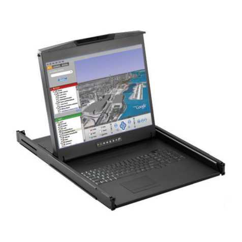
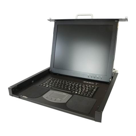
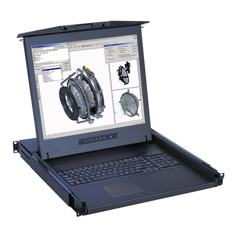
The RACKMUX®KVM Drawer with 4K Video USB KVM Switch combines a rackmount 4K LCD monitor, keyboard, and touchpad
mouse (RACKMUX) with 4K Video USB KVM switch (UNIMUX) in a space-saving 1RU industrial strength drawer. Available with
4, 8 or 16 port 4K Video USB KVM switch.
Features Include:
Available with forward-folding 17.3" Active Matrix LCD HDMI flat panel monitor.
Video Resolution 3840x2160@30Hz / 1080p@60Hz.
Integrated 4K Video USB KVM switch.
oOn screen display for controlling switch and modifying settings, uses attached mouse and keyboard.
oPasses embedded audio
oHDCP 1.3 Compliant
oSupports HDMI 1.4
Control up to 16 USB enabled computers with HDMI outputs.
Any HDMI source or display can be connected by using HD-xx-MM cable (not included).
Torque-friction hinges - monitor does not wobble, spring, or slam shut.
Compact, heavy-duty tactile keyboard with 17-key numeric keypad.
Rugged steel construction with durable powder coat finish.
LCD auto-shutoff in closed position.
Drawer locks into place when open to prevent it from sliding in and out of the rack.
Materials Included:
RACKMUX KVM Drawer with integrated UNIMUX switch
IEC Power cord- country specific
Single-Person Installation mounting kit
DB9 Female-to-RJ45 Female adapter
5 foot RJ45-to-RJ45 CAT5 patch cable
URL slip with link to PDF file of this manual
Material Not Supplied, but may need to be ordered
Cables can be purchased from Network Technologies Inc by calling 800-RGB-TECH (800-742-8324) or 330-562-7070
or by visiting our website at www.networktechinc.com.

NTI RACKMUX-4K17-N-16HD4K RACKMOUNT DRAWER WITH 4K VIDEO USB KVM SWITCH
2
RACKMUX SINGLE-PERSON INSTALLATION
Your NTI RACKMUX Drawer was designed for easy installation by one person with a minimum of tools and effort. Follow the
simple steps below to quickly install your RACKMUX Drawer.
If you would like to see a video of this installation, see the “single-person-installation”video .
1. Locate and unpack the hardware bag. Your hardware bag will include all items necessary to install the specific RACKMUX
model (see the manual that accompanied your RACKMUX drawer), including the following hardware unique to the Single-Person
hardware installation:
10- #10-32 cage nut
2- #10-32 x 1/2” flat-head machine screw
8- #10-32 x 3/4” pan-head machine screw
Toinstall the rails you will need only a tape measure and Phillips screwdriver.
2. Unpack the left and right rail assemblies. Each are labeled “Right Front” and “Left Front” to indicate their intended position and
orientation. Extend each rail assembly to the dimension required for your rack. Rail assemblies are adjustable to fit within a rack
between 24” and 40” in depth.
Rail assemblies are adjustable in length from 24” to 40”.
XXXXX
Labeled
Figure 1- Adjustable rail assemblies

NTI RACKMUX-4K17-N-16HD4K RACKMOUNT DRAWER WITH 4K VIDEO USB KVM SWITCH
3
3. Install six #10-32 cage nuts at the front of the rack in positions where the RACKMUX will be mounted (three in each side).
Install four more cage nuts at the rear of the rack in positions straight across from the upper and lower cage nuts installed in front.
Cage
Nuts
Front Rack
Support
Extender Rail
Rail Flange
Cage
Nuts
Rear Rack
Support
Extender Rail
Figure 2- Install the cage nuts
4. Install the right rail assembly. The end with the label “Right Front” mounts to the front rack support. Install only the center
screw through the rail flange to the rack support and cage nut using the #10-32 x 1/2” flat head machine screw provided. (See
image below.) Do not tighten at this time. Install the left rail assembly in the same fashion. The end with the label “Left Front”
mounts to the front rack support.
5. Install two #10-32 x 3/4” pan-head screws in the rear of each rail assembly as shown below. Do not tighten at the time.
Install two
screws in each
side at the rear
Install one flat
head screw in
the center in
each side at
the front
Rack Front
R
ack Rear
Figure 3- Install the rail assemblies

NTI RACKMUX-4K17-N-16HD4K RACKMOUNT DRAWER WITH 4K VIDEO USB KVM SWITCH
4
6. Measure the distance between the inside of the rails at the front of the rack. Adjust the distance to 17-1/4” and tighten the flat-
head screws to the rail flanges securely.
17-1/4"
Front Rack Supports
Left Rail
Right Rail
Figure 4- Check spacing of the rails
7. Lineup the rail guides on the RACKMUX drawer with the slots in the front of the left and right rails and slide the drawer into the
rack. The rail guides should be positioned such that the wide lip of the guide is on the backside of the rail. Slide the drawer in
completely.
Rail guides
View of rail guide from the front of the rack support View of rail guide from the backside of the rail
Figure 5- Rail guides
Wide lip of rail g
u
ide

NTI RACKMUX-4K17-N-16HD4K RACKMOUNT DRAWER WITH 4K VIDEO USB KVM SWITCH
5
8. Apply four more #10-32 x 3/4" pan-head machine screws (two for each) through the holes in the drawer flanges, through the
holes in the left and right rails, into the cage nuts in the rack supports. Tighten each securely.
Apply two
more screws
on each side
Figure 6- Apply remaining screws to complete installation
9. Tighten securely the four screws applied to the rear rail flanges in step 4.
10. Make your cable connections according to your RACKMUX Drawer instructions.
Your NTI RACKMUX Drawer is now installed and ready for cable connections.
There should
be a total of
six screws at
the front now.

NTI RACKMUX-4K17-N-16HD4K RACKMOUNT DRAWER WITH 4K VIDEO USB KVM SWITCH
6
CABLE CONNECTIONS
Connect Video Sources
1. Connect each of the HDMI video sources to the ports on UNIMUX marked “HDMI Inx” (x = 1-16).
2. Connect the power cord to the AC input and plug it in.
3. Press the switch to power the RACKMUX ON. In approximately 40 seconds the UNIMUX will boot up and be ready to use.
4. The RACKMUX keyboard provides keyboard control of the OSD menu of the UNIMUX. The UNIMUX supports transparent
USB device connection such that the keyboard and touchpad mouse will also control the keyboard and mouse functions on any
connected PC.
5. For each video source that is a PC, connect a USB2-AB-0-5M-5T cable (sold separately) between a USB type A female user
device port on a CPU and a USB Type B female port on the SPLITMUX.
Figure 7- Connect each CPU and video source
6. Power-ON the video sources and CPUs.
The CPUs can be powered at any time although if a CPU needs a keyboard and/or mouse at power-ON it should be
powered after connecting to and powering-ON the RACKMUX.
Note: The order in which the CPUs and switch are powered up does not matter. A power strip can be used.
7. Power-ON the RACKMUX. (The RACKMUX can be powered at any time.)

NTI RACKMUX-4K17-N-16HD4K RACKMOUNT DRAWER WITH 4K VIDEO USB KVM SWITCH
7
Terminal Connection for RS232
If control via serial connection is going to be used, serial control can be achieved by connecting a control terminal to the “RS232”
port .
To use the “RS232” port, connect one end of a CAT5 patch cable (supplied) to the port labeled “RS232” on the rear of the
UNIMUX. Plug the other end of the CAT5 cable into an RJ45-to-DB9F adapter (supplied), and connect the adapter to the RS232
port on the control terminal.
Figure 8- RS232 Terminal Connection
Connect Extra Device
On the front of the RACKMUX is an additional USB Type A port to be used, if desired, for an extra accessory. Any low or full
speed USB device may be connected to this port to be used. This port is fully compliant with USB standard 1.1.
Note: In order for the optional USB device port to be usable, the USB port on the rear of the RACKMUX must be
connected to a USB enabled CPU (a 2 meter USB cable is supplied).
Note: If a USB keyboard or mouse is connected, operation of the RACKMUX keyboard or mouse may cause
unpredictable results. Do not try to use both mice or both keyboards at the same time.
Note: If a USB 2.0 device is
connected to the optional
USB device port, it will
operate at USB 1.1 speed.
Figure 9- Connect a USB 1.1 device to the front (optional)

NTI RACKMUX-4K17-N-16HD4K RACKMOUNT DRAWER WITH 4K VIDEO USB KVM SWITCH
8
FEATURES AND FUNCTIONS
# LABEL PHYSICAL DESCRIPTION
1 Power Button press to turn only the LCD monitor ON and OFF
2 --- Green/Red LED Indicates operation status
Green = Power-ON, Video Input Signal OK
Red = Suspend / Stand-by, or no Video Input Signal
3 Menu Button press to turn ON the OSD menu
4 Down Arrow Button press to move the cursor in the OSD menu down
5 Up Arrow Button press to move the cursor in the OSD menu up
6 Select Button press to select a menu item (when OSD menu is ON) or press to auto adjust the
video quality (when OSD menu is OFF)
7 NumLock Green LED illuminates when the number lock is ON
8 CapsLock Green LED illuminates when CapsLock is ON
9 Scroll Lock Green LED illuminates when the Scroll Lock keyboard feature is ON.
10 --- 3-button mouse for controlling mouse movements on the monitor and controlling the computer
11 --- Keylock to prevent unauthorized use of the RACKMUX
12 --- Auto Shut-OFF switch automatically shuts OFF the LCD display when the monitor is folded down
13 --- Keyboard for manual data entry and computer control
14 --- USB Type A for connection of USB 2.0 device (flash drive, printer, CAC reader, etc)
15 --- LCD Display for viewing the video signal from the connected CPU
16 RS232 RJ45 female for attaching RS232 interface cable from a CPU to control the functions of one or
more switches
17 CPU INxUSB Type B
female for connection of device cables from PCs- to provide control over mouse and
keyboard functions
18 HDMI INx HDMI female for connection of video cables from video sources supplying Hi-Definition video
19 --- IEC Connector for attachment of the IEC power cord to power the RACKMUX drawer
20 --- Main Switch for powering ON and OFF the RACKMUX drawer
21 USB Devices USB Type A For connection of additional USB devices to connect to CPUs

NTI RACKMUX-4K17-N-16HD4K RACKMOUNT DRAWER WITH 4K VIDEO USB KVM SWITCH
9
CONTROL METHODS
The UNIMUX, when built into a RACKMUX, can be controlled using any of three methods;
Command Mode using the local keyboard, and touchpad mouse
Mouse clicks from within some menus of Command Mode
Using the Command Line Interface through RS232
Command Mode
Once the UNIMUX is properly connected, the UNIMUX will enable a connection to be made between the CPUs attached to its
VIDEO and CPU ports and the RACKMUX user. The RACKMUX keyboard and mouse will, by default, control the PC supplying
the active video. The keyboard and mouse can also be used for controlling Standard Mode functions as well as OSD Mode.
Keyboard Control
Keyboard control of the UNIMUX can be achieved using Command Mode - operated using the RACKMUX keyboard and mouse in
conjunction with OSD menus superimposed onto the monitor.
By pressing <Ctrl> + < ` > (accent key), the user can enter Command Mode. The NumLock, CapLock and Scroll Lock LEDs
will illuminate and stay ON while in Command Mode. Once in Command Mode, typing a series of commands will cause the
UNIMUX to connect the user to any one CPU connected to the switch. Pressing the <Esc> key will exit Command Mode.

NTI RACKMUX-4K17-N-16HD4K RACKMOUNT DRAWER WITH 4K VIDEO USB KVM SWITCH
10
USER ACCESS FUNCTIONS
Introduction
The OSD menu enables a user to name the CPUs connected to the UNIMUX and connect to them using that name from a single
keyboard and mouse. The OSD is positioned on the user's monitor, displaying 8 CPU names at a time. The screen can be used
for switching as well as editing the CPUs’ names. Through the OSD menu, the user can operate the UNIMUX to have the switch
cycle through 3 extended modes of operation: COMMAND, BROADCAST, and SCAN .
Command Mode
When entering the Command Mode from the keyboard using the <Ctrl> + <`> (accent key), the NumLock, CapLock and Scroll
Lock LEDs will illuminate and stay ON and the OSD menu will automatically appear on the monitor. This provides a visual way
to control the UNIMUX.
Navigation
Keyboard Key Action
Up/Down Arrow Select previous or Next port (while in the Port List)
Page Up/Down Advance to previous or to the next page of the Port List
Home Select the first port in the displayed port list
End Select the last port in the displayed port list
<number> Select and switch to Port Number
Enter Execute that selection
Shift-Tab Move to previous field in the menu
Tab Move to next field in the menu
Space Toggle the selection of the highlighted field
F1 Bring up the Help Menu (see Figure 11)
Esc Back up in the menu to the previous page or Exit the OSD menu
The mouse can also be used to control the UNIMUX within the Command Mode menu.
The mouse cursor can be moved to anywhere on the OSD menu. Text in blue is selectable. The user
can then single-click the left mouse button to make a selection, double-click to perform that function.
Ports listed on the screen can be selected by moving the cursor onto that port and clicking. If the USB Device
Reminder is enabled, an additional press of the <Enter> key will be needed (unless you press <Esc> and cancel the
change).
To scroll through the displayed ports on the screen simply click on the up and down arrows located to the right of the
port names displayed.
Note: The user must
exit Command Mode
to type to a CPU.
To exit Command
Mode, either mouse
click on "Exit" OR
press <ESC> on the
keyboard.
Click to sort b
y
p
ort number Click to sort al
p
habeticall
y
Click to scroll
Figure 10- Port List (Main Menu)

NTI RACKMUX-4K17-N-16HD4K RACKMOUNT DRAWER WITH 4K VIDEO USB KVM SWITCH
11
To change the way the port list is displayed, the user can click on the "#" sign to have the list displayed numerically, or click in
"Name" to have the list displayed alphabetically. If the user decides to rename the ports to something easy to remember, listing
the alphabetically may be the most desired setting.
Figure 11- Help Menu
Settings Menu
From the Settings Menu the user can quickly change the status of the major functions in the UNIMUX.
Figure 12- Settings Menu
The user can change the status of Scan Mode and Broadcast Mode between Disabled (red text) and Enabled (green text). Click
on the status indicated to toggle it.
The user can enable or disable the "Stop USB Device" Reminder notice. While enabled, any time the user attempts to change to
a different port number, a warning message will pop up forcing a decision to either proceed with or cancel the attempt. This
provides opportunity for the user to properly eject a USB flash drive or any other device that may be harmed by an abrupt loss of
connection between the user and the PC the flash drive is connected to.

NTI RACKMUX-4K17-N-16HD4K RACKMOUNT DRAWER WITH 4K VIDEO USB KVM SWITCH
12
To respond to the Stop USB Device warning, either click "Enter" or "Esc" with the mouse, or use keyboard keys.
Figure 13- Stop USB Device Reminder warning
From the Setting Menu the user can also toggle the OSD menu to either be Opaque (have solid color) when on the display, or to
be translucent (see-through). Click on the setting to toggle it.
Broadcast Mode
Broadcast Mode enables the user to select specific ports (see Figure 15) to be active in Broadcast Mode. Only the selected ports
will receive keyboard messages in Broadcast Mode.
To activate or deactivate Broadcast Mode from the Command Mode menu, from the main menu click on Settings. From the
Settings menu, click to display either Disabled (deactivate) or Enabled (activated).
Broadcast Mode enables the user to type characters to more computers simultaneously. From the Administrator Settings-
Broadcast List menu (see page 19) the user can edit the list of ports that receive data in Broadcast Mode. A port doesn’t receive
broadcast data the port is not in the Broadcast Mode list
Note: The user must type somewhat slowly when in Broadcast Mode (less than 20 wpm).
Note: While in Broadcast Mode the mouse will not work.
Figure 14- Settings Menu

NTI RACKMUX-4K17-N-16HD4K RACKMOUNT DRAWER WITH 4K VIDEO USB KVM SWITCH
13
Figure 15- Broadcast List
From the Broadcast List, click on a port number to toggle its status. Ports displayed in green are included in the broadcast, ports
in red are not. The quickly select all ports, click on "Enable All". To quickly deselect all ports, click on "Disable All".
Selections are automatically saved.
Scan Mode
Scan Mode enables the user to select specific ports (see Figure 17) to be active in Scan Mode. Only the selected ports will be
scanned in Scan Mode.
To activate or deactivate Scan Mode from the main menu click on Settings. From the Settings menu, click to display either
Disabled (deactivate) or Enabled (activated).
Figure 16- Settings Menu
When in Scan Mode the switch scans to each port selected in the Scan List. Scan Mode will connect to selected ports, whether
those ports are powered ON or not. The port with the CPU powered-ON remains active while in use until it becomes idle for the
configured dwell time (Figure 17) (default time-out period is 15 seconds) before switching to the next selected CPU port. See
Command Mode section above for configuring the scan dwell time.

NTI RACKMUX-4K17-N-16HD4K RACKMOUNT DRAWER WITH 4K VIDEO USB KVM SWITCH
14
Note: The keyboard and mouse must remain idle for the full scan dwell time before the switch selects the next active
port.
Figure 17- Scan List
From the Scan List, click on a port number to toggle its status. Ports displayed in green are included in the scanned, ports in red
are not. Toquickly select all ports, click on "Enable All". To quickly deselect all ports, click on "Disable All".
Selections are automatically saved.
Click on the number across from "Scan Dwell Time" to select the field and enter a number between 0 and 255 (default is 15) to
configure the length of time the connection will remain with a CPU before switching to the next CPU while the UNIMUX is in Scan
Mode.
Normal Mode
When the UNIMUX is not in Command, Broadcast, or Scan mode, the user is in Normal Mode, controlling the CPU to which the
user is connected through the USB KVM switch.

NTI RACKMUX-4K17-N-16HD4K RACKMOUNT DRAWER WITH 4K VIDEO USB KVM SWITCH
15
Administrator Settings
The Administrator Settings menu provides access to specific administrative functions of the UNIMUX. From the Main Menu
select Settings, then Administrator Settings.
Figure 18- Administrator Settings
Click the Port Name List to bring up a page where the names displayed for the UNIMUX and for each port can be edited.
Clicking on the Port Name List or Scan List will bring up the list of ports to be set to be affected by Broadcast and Scan modes
(pages 12 and 13)

NTI RACKMUX-4K17-N-16HD4K RACKMOUNT DRAWER WITH 4K VIDEO USB KVM SWITCH
16
Port Name List
The Port Name List is provided to enable the user to edit the names of the ports and switch. Port names and the switch name
can be up to 30 characters in length. The user can customize the UNIMUX to make switching to frequently used ports more
easily. The Port Name List is accessed from the Administrator Settings menu (page 15).
Figure 19- Port Name List
To quickly return the switch to factory settings for the switch name, port names, and all configured settings, click on "Restore
Defaults".
To Edit the Switch name and Port Names:
Using the Keyboard: Using the Mouse:
1.Press <Tab> to move between fields 1.Click on the field to select it
2.Press <Enter> to select a field to edit 2.Type the text to be used
3.Type the text to be used 3.Press <Enter> to save it
4.Press <Enter> again to save it
Editing keyboard keys for name fields include: Backspace, Delete, Right Arrow, Left Arrow, Home, End and Insert.
Other manuals for RACKMUX Series
4
This manual suits for next models
1
Table of contents
Other NTI LCD Drawer manuals

NTI
NTI RACKMUX-T15 Technical manual

NTI
NTI RACKMUX-V15 User manual

NTI
NTI RACKMUX-V15-4UNV User manual

NTI
NTI RACKMUX-V17-N User manual

NTI
NTI RACKMUX-VS17-T User manual

NTI
NTI RACKMUX-V15 User manual

NTI
NTI RACKMUX-T15-CS16/8 Owner's manual

NTI
NTI RACKMUX Series User manual

NTI
NTI RACKMUX-V17-N-8/4USBHDU-IP User manual

NTI
NTI RACKMUX Series User manual