22. 01. 18. Leaflet Number 671730 3
The EMC Directive
2014/30/EU
The Low Voltage
Directive
2014/35/EU
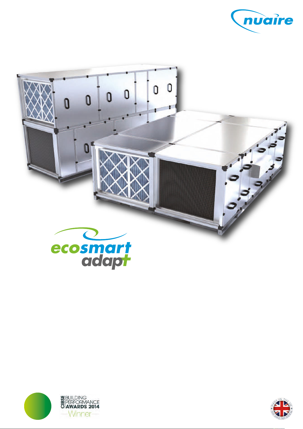
XBOXER XBC 75 & 85 (AT Models)
Supply & Extract Ventilation Unit with Heat Recovery
Installation and Maintenance
1.0 XBC 75 & 85 Horizontal Ecosmart Adapt
(Trend) (AT) Control Models
The information contained in this document provides details of
installation, operation and maintenance for installers and users of
the XBOXER XBC75 & 85 Supply and Extract Ventilation Units with
Heat Recovery.
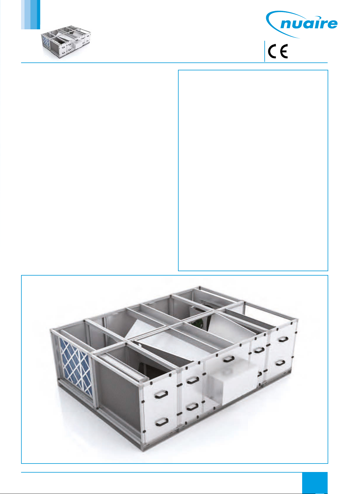
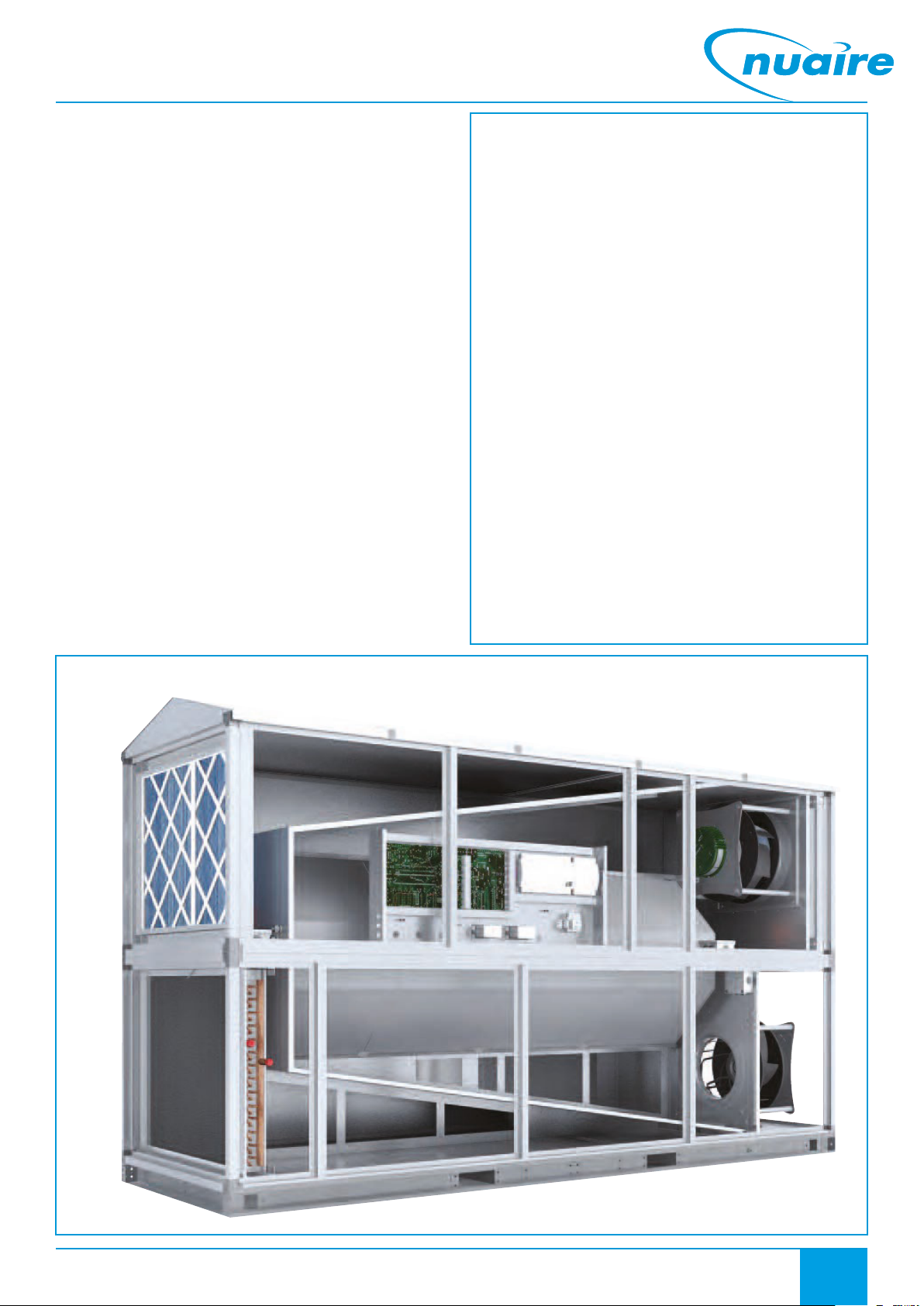
This supply and extract air handling unit range comprises an
combination of high efficiency centrifugal fans with EC motors, a
counterflow design plate heat exchanger, filters, optional heaters
(LPHW and Electric) and a casing with high mass acoustic treatment.
The one-piece ventilation unit shall be constructed with double
skinned Aluzinc panels on an aluminium Pentapost frame with integral
acoustic mineral fibre ensuring low breakout noise levels. The unit
shall incorporate a high efficiency aluminium counterflow plate heat
exchanger matrix with a thermal efficiency of up to 92%, fitted with
a segmented 100% bypass facility and actuator (patent app. for)
operating under automatic control.
A range of matched, side by side internal and external attenuators
(horizontal units) and double deck internal and external attenuators
(vertical units) with a similar construction method to that of the unit is
available.
General information regarding performance and specifications for the
equipment may be obtained from our Technical Literature, and / or
project specific documentation.
Code description: XBOXER XBC Ventilation Unit
XBC 75 - H - LAT - R - WP
| | | | | | |
1 2 3 4 5 6 7
1. XBOXER XBC Range
2. Unit size 75 & 85
3. H = Horizontal Side by Side layout
4. N = No Heater
L = LPHW Heater
E = Electric Heater
5. AT = Adapt (Trend)
6. R = Opposite arrangement
7. WP = Separate Matched Weather Roof if required
Code description: Matched Attenuator
XBC 75 - H - SIL900
| | | |
1 2 3 4
1. XBOXER XBC Range
2. Unit size 75 & 85
3. H = Horizontal Attenuator
4. SIL900 = 900mm Attenuator
SIL900WP = 900mm Attenuator with roof
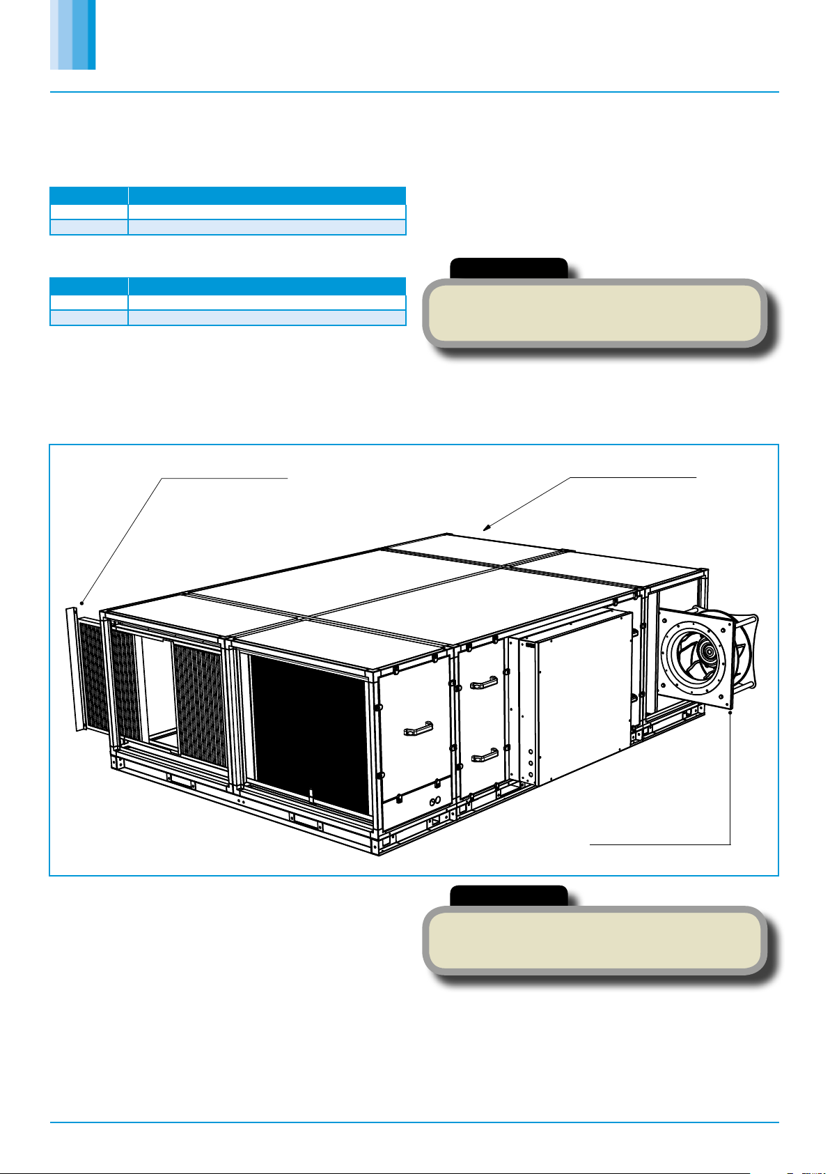
Figure 1. Layout Overview of the XBC horizontal unit, viewed from
above with lid removed.