manuals.online logo
Brands
  1. Home
  2. •
  3. Brands
  4. •
  5. NuAire
  6. •
  7. Fan
  8. •
  9. NuAire dMEV+H User manual

NuAire dMEV+H User manual

1.0 Introduction
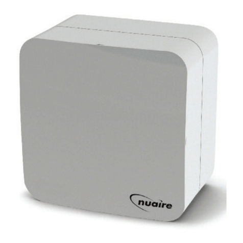
The dMEV+H is a 2 speed axial extract fan has been designed for
continuous ventilation for kitchens or wet rooms and should be
installed using 100mm dia. ducting.
Speed settings are fixed at either Low Speed and Low Boost or
High Speed and High Boost (See Section 9.0 for Details).
As a default, the fan is set to achieve low speed (6 l/s – wet rooms)
to adjust to high speed (8 l/s - kitchen) refer to section 9.0.
2.0 Handling
Always handle the the fan carefully to avoid damage and distortion.
4.0 Spacer installation (if required)
3.0 Installation
The installation must be carried out by competent personnel in
accordance with the appropriate authority and conforming to all
statutory and governing regulations i.e. IEE, CIBSE, CCHSE, HVCA etc.
The unit is for indoor use only, and is suitable for through wall and
ceiling installation. Mount on a secure, vibration free surface away
from any direct source of heat and areas where it would be subjected
to water spray.
The maximum permissible ambient temperature is 50°C.
dMEV+H Box Contents
Fan unit (Including 2 part inlet grille and 2 fixing screws), wiring
grommets (2 off), a cable clamp c/w screws and spacer.
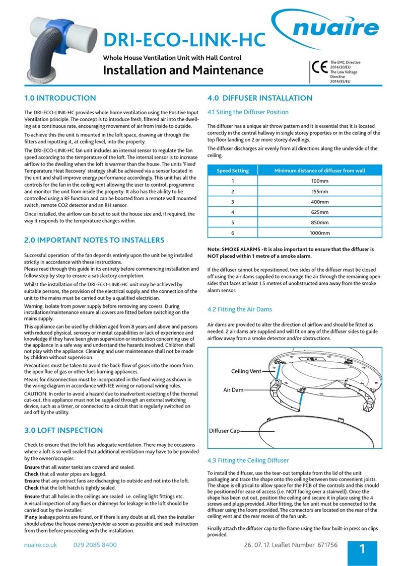
dMEV+H
Decentralised Mechanical Extract Ventilation
2 Speed Axial Extract Fan with Humidity Enabler
Installation Guide
The EMC Directive
2014/30/EU
The Low Voltage
Directive
2014/35/EU
10. 05. 17. Leaflet Number 671665
1
Figure 1.
DMEVH & DMEV+H ONLY
Snap off top lug (highlighted in grey)
(eight lugs in total, two in each corner)
Corner post once top lugs
have been removed
Fig. 1 Spacer Installation Having established the mounting position
for the unit, mark the centres of duct hole and four fixing points
using the template provided on page 5.
Core cut the centre duct hole, drill and plug mounting holes.
When using surface mounted cabling select the most appropriate
cable entry position and carefully trim out the inner and outer cable
cut-outs.
Secure spacer to the wall / ceiling (fixings supplied by others). Note:
use wood screws not countersink screws to avoid distorting the skirt.
Chased in Cable:
Feed the cable through the spacer to pass through back plate for
when installing fan.
Wire outlet
position
Nuaire: A Trading Division of Polypipe Limited Western Industrial Estate Caerphilly United Kingdom CF83 1NA
T: 029 2088 5911 F: 029 2088 7033 E: [email protected] W: www.nuaire.co.uk
5.0 Wall / Ceiling Installation
a) lacing the Fan Unit.
Having established the mounting position for your fan, you need to
cut a suitable size hole through the Wall or Ceiling to accommodate
the 100mm dia. Spigot on the fan unit. Place the fan unit into the
hole and mark up 4 fixing points (4 corners of fan unit rear section,
shown in fig 2a).
Drill marked up holes and add suitable fixing plugs (Supplied by
others).
b) repare wiring for the fan.
Wiring can be fed through either the back or the right hand side of
the fan unit rear section.
c) Fitting the Fan Unit.
Insert 100mm dia. ducting (Pre-cut the duct length to suit the
wall/ceiling that duct is going through) through the hole previously
cut, then insert the fan unit into the duct and secure using suitable
fixings (Supplied by others). Ensure that the wiring is fed through the
fan unit rear section at the chosen exit point.
d) Wiring the Fan Unit.
Please revert to section 8.0 for full wiring diagram.
Ensure supply cable is clamped inside the unit (Clamp and Screws
supplied).
e) Setting the Humidity Trigger set point.
Please revert to section 10.0 for Set point options.
f) Finishing the Install.
Once the unit has been wired and humidity trigger set point has
been selected the front facia of the fan unit can be fitted.
Once cover and rear section are slotted together, fit the 2 fixing
screws (supplied) to the bottom face, fig. 2b.
10. 05. 17. Leaflet Number 671665
2
Installation and Maintenance Decentralised Mechanical Extract Ventilation 2 Speed Axial Extract Fan
Figure 2a.
Motor Cap.
Fixing Screws.
Figure 2b.
6.0 Dimensions
7.0 Electrical
Voltage: 230V
Frequency: 50Hz
8.0 Wiring
Installation and Maintenance Decentralised Mechanical Extract Ventilation 2 Speed Axial Extract Fan
10. 05. 17. Leaflet Number 671665
3
130
98.5
4
Figure 3. dMEV+H fan unit. Figure 4. dMEV+H fan and room grille.
96
146
175
127.5 50.5
102
125
190
140
Figure 5. dMEV+H fan unit rear section. Figure 6. dMEV+H fan and room grille side section.
Unit serving bathroom or kitchen (optional boost)
Mains
230V
50Hz
U
1
2
3
SL
N
L
2/3 Pole
isolator
Fan unit
Optional
remote switch
N
L
Fuse 2A
Unit serving bathroom (via light switch)
Mains
230V
50Hz
1
2
3
SL
N
L
3 Pole
isolator
Fan unit
N
L
Fuse 2A
Lamp
Figure 7.
NOTE: In the event of voltage transients or other EMC interference on the mains
supply the fan may go into boost for 3 seconds or possibly for the run on time period.
Operation will be restored to normal after the interference stops.
If severe EMC interference causes the fan to go into permanent boost the mains
power should be reset to restore functionality.
If high levels of RF interference causes the fan to go into boost during the period of RF
interference EMC mitigation procedures may be required. Contact Nuaire service dept
for further support.
9.0 Speed Settings
The dMEV+H is pre-set to achieve 6 l/s Continuous and 13 l/s on
boost. This can however be changed to 8 l/s Continuous and 18 l/s
on boost. To change these speed setting you will need to change the
jumper position within the fan unit (fig. 8). To do this you will need
to remove the 2 fixing screws on the motor cap (shown in fig 2a).
Installation and Maintenance Decentralised Mechanical Extract Ventilation 2 Speed Axial Extract Fan
Technical or commercial considerations may, from time to time,
make it necessary to alter the design, performance and
dimensions of equipment and the right is reserved to make such
changes without prior notice.
10. 05. 17. Leaflet Number 671665
4
11.0 Maintenance
The fan unit does not require any maintenance. However, for
optimum performance, it is advisable to remove any accumulated
dust with a low power vacuum cleaner.
Note: Installation and Maintenance of the equipment must
be as directed in the instructions provided with the unit.
12.0 Warranty
The 5 year warranty starts from the day of delivery and includes
parts and labour for the first year. The remaining 4 years covers
replacement parts only.
This warranty is void if the equipment is modified without
authorisation, is incorrectly applied, misused, disassembled, or not
installed, commissioned and maintained in accordance with the
details contained in this manual and general good practice.
Telephone 02920 858 400
SL L N
Low High
Unit is fixed speed.
Select between either
Low or High speed with
the jumper position.
i.e. Bathroom installation
Low speed (Pre-set
factory position).
Speed ow ow High High
Setting: Continuous Boost Continuous Boost
Air Flow: 6 l/s 13 l/s 8 l/s 18 l/s
Figure. 8.
Figure 9a. Figure 9b.
Humidity sensor
Humidity switch
230V Live
230V Neutral
230V Switch live
1
2
3
10.0 Humidity Set oint
The dMEV+H is pre-set to boost when it senses a relative humidity
(%RH) of 80% however this can be changed to suit the installation.
To do this you will need to access the PCB within the unit.
On the PCB you will need to alter the humidity switch (fig 9a)
configuration to suit the configurations in (fig 9b).
ON ADE02
1 2
ON ADE02
1 2
ON ADE02
1 2
ON ADE02
1 2
60% RH
70% RH
80% RH
90% RH
Switch actuator
The product warranty applies to the UK mainland and in accordance
with Clause 14 of our Conditions of Sale. Customers purchasing from
outside of the UK should contact Nuaire International Sales office for
further details.
13.0 After Sales
For technical assistance or further product information, including spare
parts and replacement components, please contact the After Sales
Department.
Installation and Maintenance Decentralised Mechanical Extract Ventilation 2 Speed Axial Extract Fan
14.0 Skirt Spacer Template
A
B
Wire outlet
positions
BASE
Note, if printing document check scale.
A = 147.8mm
B = 100.7mm
10. 05. 17. Leaflet Number 671665
5
ENSURE THE “BASE” ALIGNS WITH THE
“BASE” MARKINGS ON THE MOULDING

This manual suits for next models

1

Other NuAire Fan manuals

NuAire CYFAN-C Instruction Manual

NuAire

NuAire CYFAN-C Instruction Manual

NuAire MRXBOX95ABWM2QA12338 Instruction Manual

NuAire

NuAire MRXBOX95ABWM2QA12338 Instruction Manual

NuAire DS1A-NES User manual

NuAire

NuAire DS1A-NES User manual

NuAire MRXBOX-ECO3-1Z User manual

NuAire

NuAire MRXBOX-ECO3-1Z User manual

NuAire ecosmart MEV-DC Instruction Manual

NuAire

NuAire ecosmart MEV-DC Instruction Manual

NuAire ILM Series User manual

NuAire

NuAire ILM Series User manual

NuAire MRXBOXAB-ECO4-AESC User manual

NuAire

NuAire MRXBOXAB-ECO4-AESC User manual

NuAire ecosmart MRXBOX95-WM2-AE Instruction Manual

NuAire

NuAire ecosmart MRXBOX95-WM2-AE Instruction Manual

NuAire Drimaster365 Installation guide

NuAire

NuAire Drimaster365 Installation guide

NuAire Xboxer XBC+ Ecosmart Classic E User manual
NuAire

NuAire Xboxer XBC+ Ecosmart Classic E User manual

NuAire DRI-ECO-HEAT-HCS User manual

NuAire

NuAire DRI-ECO-HEAT-HCS User manual

NuAire DRI-ECO-HEAT-HCS User manual

NuAire

NuAire DRI-ECO-HEAT-HCS User manual

NuAire MAB-204X60 User manual

NuAire

NuAire MAB-204X60 User manual

NuAire NALSC Instruction Manual

NuAire

NuAire NALSC Instruction Manual

NuAire MRXBOXAB-ECO3-1ZSW User manual

NuAire

NuAire MRXBOXAB-ECO3-1ZSW User manual

NuAire MRXBOX-AV4 Instruction Manual

NuAire

NuAire MRXBOX-AV4 Instruction Manual

NuAire TRA Series User manual

NuAire

NuAire TRA Series User manual

NuAire NOXMASTER Series Instruction Manual

NuAire

NuAire NOXMASTER Series Instruction Manual

NuAire ECOSMART XTRACTOR Manual

NuAire

NuAire ECOSMART XTRACTOR Manual

NuAire SLIMAIRE/NA Series Instruction Manual

NuAire

NuAire SLIMAIRE/NA Series Instruction Manual

NuAire MRXBOX95B-350 WC Instruction Manual

NuAire

NuAire MRXBOX95B-350 WC Instruction Manual

NuAire MRXBOX95-WH1 Instruction Manual

NuAire

NuAire MRXBOX95-WH1 Instruction Manual

NuAire ILM+ Series User manual

NuAire

NuAire ILM+ Series User manual

NuAire MRXBOX-SIL3 Instruction Manual

NuAire

NuAire MRXBOX-SIL3 Instruction Manual

Popular Fan manuals by other brands

HAEGER Tower Wind User instructions

HAEGER

HAEGER Tower Wind User instructions

Modern Forms Morpheus III installation instructions

Modern Forms

Modern Forms Morpheus III installation instructions

Brookstone STACKFAN manual

Brookstone

Brookstone STACKFAN manual

HTW CIRCLE R32 Owners and installation manual

HTW

HTW CIRCLE R32 Owners and installation manual

Makita DCF201Z instruction manual

Makita

Makita DCF201Z instruction manual

Brofer MDF25L Installation and operation manual

Brofer

Brofer MDF25L Installation and operation manual

Hurricane W Instruction guide

Hurricane

Hurricane W Instruction guide

aerauliqa AD1400A manual

aerauliqa

aerauliqa AD1400A manual

KDK W56WV Operating and installation instructions

KDK

KDK W56WV Operating and installation instructions

Vents Boost 150 user manual

Vents

Vents Boost 150 user manual

Fanimation TRIAIRE MAD8515 Series manual

Fanimation

Fanimation TRIAIRE MAD8515 Series manual

Superior RT 23I user manual

Superior

Superior RT 23I user manual

Sealey SDF12H quick start guide

Sealey

Sealey SDF12H quick start guide

Kruger CFT Series General instructions

Kruger

Kruger CFT Series General instructions

Goobay 62061 user manual

Goobay

Goobay 62061 user manual

Pifco P51001 manual

Pifco

Pifco P51001 manual

Vortice Gordon W 30/12 P Instruction booklet

Vortice

Vortice Gordon W 30/12 P Instruction booklet

S&P TTT Series manual

S&P

S&P TTT Series manual

manuals.online logo
manuals.online logoBrands
  • About & Mission
  • Contact us
  • Privacy Policy
  • Terms and Conditions

Copyright 2025 Manuals.Online. All Rights Reserved.