manuals.online logo
Brands
  1. Home
  2. •
  3. Brands
  4. •
  5. NuAire
  6. •
  7. Fan
  8. •
  9. NuAire MVHR-LP Instruction Manual

NuAire MVHR-LP Instruction Manual

1Leaflet Number 671281 March 2007
Nuaire Home Ventilation Western Industrial Estate Caerphilly nited Kingdom CF83 1NA
Telephone: 08705 002555 Facsimile: 08705 002666
Email: [email protected] www.nuaire.co.uk
Figure 1.
MVHR-LP Units
Mechanical Ventilation with Heat Recovery
Installation and Maintenance
Figure 3.
Cut through the
acoustic foam round
the circumference of
the damper
Damper can be
swivelled on the
2 body casing
hinges
Fixing screw hole.
Bracket tongues
engage with casing
slots, then unit
rotated up to align
with fixing
screw hole.
Slots in casing
either side of
unit to allow
alternative
mounting option.
Figure 4.
When spigot is in
position, damper can
be adjusted using a
screwdriver
Figure 2.
Discharge
Supply
Supply
Extract
Extract
Intake
Access cover on underside.
1 0 Introduction
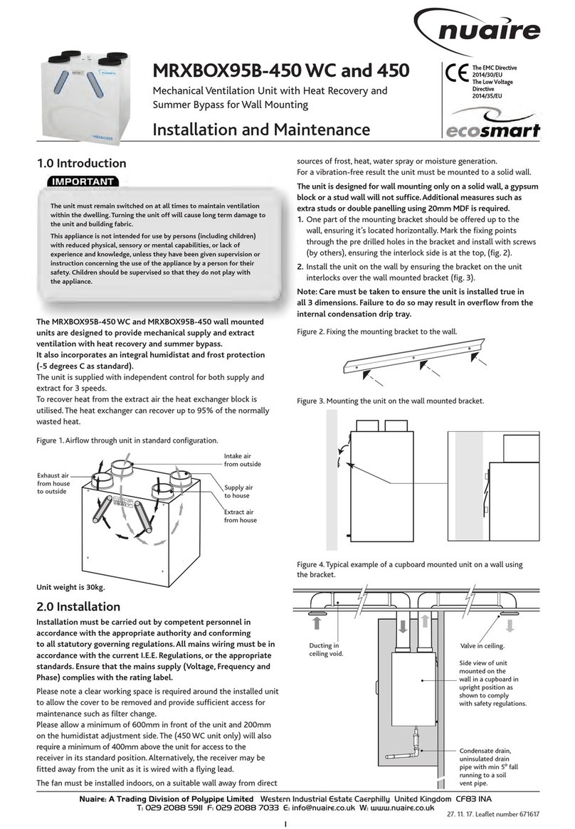
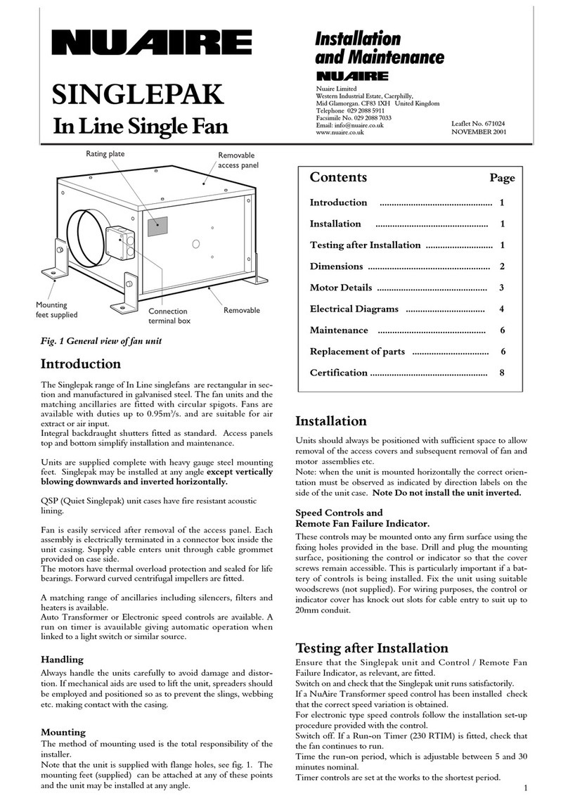
The Nuaire MVHR-LP unit is designed to provide
mechanical supply and extract ventilation with heat
recovery
The unit is fitted with two fans with ‘dial-a-duty’ control
circuit where the actual volume flow rates can be pre-set
at the commissioning stage. Once the flow rates are set
up, the fans will run at speeds necessary to produce the
desired flowrate if the system resistances are within the
operating envelope. A plate heat-exchange constructed from
recycled PVC is used to provide up to 70% heat recovery.
2 0 Installation
Installation must be carried out by competent personnel
in accordance with the appropriate authority and
conforming to all statutory and governing regulations
The fan must be fitted indoors, away from any direct
sources of heat, water spray or moisture generation.
Temperature range -5OC to 40OC.
The integral mounting bracket supplied can be offered up to
position, the fixing points marked through and the bracket
installed with 4 screws (by others).
Offer the unit into position and locate the bracket into the
slots in the case before fixing with the single bracket fixing
screw.
Various damper/inlet spigot positions can be utilised as
required to suit the system ductwork and extract grilles.
To reduce air leakage, spigots should be sealed to the unit
by silicone sealant or similar (by others).
All inlet dampers are ’closed’ as knockouts when delivered
but can be opened using a sharp knife. (See figure 3).
After the spigot has been fixed adjust the damper with a
screwdriver. (See figure 4).
See figure 5 for spigot location and sizes
Please note a clear working space is required around
the installed unit to allow the cover to be removed and
provide sufficient access for maintenance such as filter
change
The fan is designed to be wired direct to the mains supply
through a fused spur isolator (by others).
With the unit fixed in position and working from underneath
the installation bring the mains wiring through the chosen
rubber cable entry grommet at the new connection box.
Additional grommeted holes are provided to allow additional
wiring to each blower.
2Leaflet Number 671281 March 2007
Installation and Maintenance MVHR-LP Mechanical Ventilation with Heat Recovery
850
685
637
Bracket
fixing
VIEW FROM UNDERSIDE WITH COVER REMOVED
SIDE VIEW
MOUNTING BRACKET TOP VIEW
Mounting bracket
END VIEW
Single screw unit fixing
185
10
250
4 holes
7.5mm dia.
4 x spigot knockouts. 1 x 125mm dia. and 3 x 100mm dia.
for each supply and extract system
Cable entry 20mm
4 x end spigot
knockouts
100mm dia.
Mains
connection
box
125 dia. 100 dia.
extract extract
100 dia.
extract
100 dia.
extract
100 dia.
supply
100 dia.
supply
125 dia. 100 dia.
supply supply
125 dia.
Intake
125 dia.
discharge
2 0 Dimensions
Figure 5. Dimensions in mm.
Isolation - Before commencing work make sure
that the unit, switched live and Nuaire control are
electrically isolated from the mains supply
Please note this product must be earthed
N
L
SL
Do not use
To OP S-SPD
speed control
Internal
humidity adj.
To remote
fail indicator
ES-MEV-AVI
Calibration
Status
30
0
60
Run-on
(mins)
50
10
90
Max
Airflow
(l/s)
50
10
90
Min
Airflow
(l/s)
LVT NET TR
240V 1ph
supply
pre-wired
to terminal
box
Switch live
input
pre-wired
to terminal
box
(Terminal 1 for extract fan)
(Terminal 2 for supply fan)
3 0 Electrical Wiring 3 1 Additional Control Wiring Option
Other control wirings are available on each fan. Open the
cover of the unit to gain access to these connections on
each fan (see figure 7).
N
L
2
1
L
N
E
230V - 50Hz
Factory fitted links
N
L
1
2
3A fuse
Isolator by others
N
L
2
1
L
N
E
230V - 50Hz
Remove factory fitted
link from 'L' to '1'
N
L
1
2
3A fuse
Isolator and switch by others
Boost switch
N
L
2
1
L
N
E
230V - 50Hz
Remove all factory fitted links
N
L
1
2
3A fuse
Isolator and switches by others
Boost switches
Boost
signal fo
r
extract
fan
Boost
signal fo
r
supply
fan
The supply and extract fan within the unit are pre-wired to
an external wiring box for ease of connection. (see figure 6a
to 6c). All field wiring must be routed through a suitable
local isolator.
Figure 6a. Basic wiring. Both supply and extract will run at
constant speed. The fan duty is controlled via the 'Boost' setting.
Figure 6b. Trickle and Boost operation. Both supply and extract
will run at trickle and boost speed together. Closing the boost
switch will cause both fan to run at boost setting.
Figure 6c. Wiring for independent boost. The supply and extract fan
will trickle and boost independently.
Figure 7. Circuit board wiring.
WARNING - Before commencing work, electrically
isolate the fan unit from the mains supply
3Leaflet Number 671281 March 2007
Installation and Maintenance MVHR-LP Mechanical Ventilation with Heat Recovery
4 0 Setting to Work
Each fan is factory set to operate at trickle airflow when
power is applied and switch over to the boost flow rate
when a switched live signal is present. The pot marked ‘MIN
Airflow’ adjusts the trickle flow rate and the boost flow
rate by the pot marked ‘MAX Airflow’. These flow rates for
the supply and extract fan are adjusted separately. When
the switched live signal is removed, the fan will continue to
run at boost flow rate for a preset period as dictated by the
pot marked ‘R N-on’.
Work out the required flow rate for the supply and extract
fans (these are usually supplied by the design consultant)
and adjust the approprate pots. If these figures are not
available, please refer to the typical settings below.
No of Typical volume of Trickle/normal Boost
Bedrooms ventilated space flow rate l/s* flow rate l/s*
1 140m319 24
2 200m328 35
3 260m336 45
4 320m344 56
*These figures are given as a general guide They should only
be used if actual design figures are not available
5 0 Run-on Timer
The Run-on timer adjustment is from 0 - 60 mins. Run-on
is only available from the switched live (SL) signal
5 1 Start-up Routine
On power up or and after power failure the unit goes
through a 2 minute set-up period.
During this period the unit:
1 Starts at full speed
2 Ramps down to off
3 Restarts at 25% speed
4 Resumes normal operation
5 2 Status Light
Green light - Fan running
Red light - Fan failure
Flashing green light - Set-up period
Flashing red light - Electronics failure
5 3 Calibration
By pressing the calibration button the unit re-sets itself by
switching off for 30 seconds then re-starts at full speed
before ramping down to the desired duty. Whilst running at
full speed the status light flashes to indicate if the duty set
on the adjustment dials can be achieved (green for yes,
amber for no). Checks can be carried out in both the trickle
and boost modes. If the light flashes amber check the
resistance of the ducting, grilles etc. or turn down the
adjustment dial.
6 0 Maintenance
It is inevitable that even with filtered extract grilles as
recommended in BRE digest 398 some dust, fluff etc. will
pass through the filter, and which, if allowed, will build up
internally on motors and impellers, shortening the life of
the unit and, in severe cases, leading to overheating of the
motors. Consequently, it is strongly recommended that all
units are inspected and cleaned every six months.
70 Cleaning
Remove covers and carefully clean out interiors as
necessary. To clean the filter, remove from the unit and
wash in tepid water to which a little mild detergent has
been added. Shake out excess water and allow to dry
naturally. Replace when dry. Check for damage and
security of components. Refit covers.
8 0 Replacement of Parts
Should any component need replacing Nuaire keep extensive
stocks for quick delivery. Ensure that the unit is electrically
isolated, before carrying out any work.
When ordering spare parts, please quote the serial number
of the unit and the ARC number of the purchase if possible.
(This information will be available on the fan label)
9 0 Warranty
The 5 year warranty starts from the day of delivery and
includes parts and labour. This warranty is conditional on
planned maintenance being undertaken.
10 0 Service Enquiries
Nuaire can assist you in all aspects of service. Our service
department will be happy to provide any assistance required,
initially by telephone and If necessary arrange for an
engineer to call.
Customer Services Department
on 08705 002 555
4Leaflet Number 671281 March 2007
We declare that the machinery named below is intended to be
assembled with other components to constitute a system of
machinery The machinery shall not be put into service until the
system has been declared to be in conformity with the provisions of the
EC Council Low Voltage Directive
Designation of machinery: MVHR-LP
Machinery Types: Mechanical Ventilation with
Heat Recovery nit
Relevant EC Council Directives: 73/23/EEC (Low Voltage Directive)
Applied Harmonised Standards: EN60204-1, EN60335-2-80
Applied National Standards: BS848 Parts One, Two and Five
Signature of manufacture representatives:
Name: Position: Date:
1) C. Biggs Technical Director 12. 08. 04
2) W. Glover Manufacturing Director 12. 08. 04
DECLARATION OF INCORPORATION AND INFORMATION FOR SAFE INSTALLATION,
OPERATION AND MAINTENANCE
DECLARATION OF CONFORMITY
We declare that the machine named below conforms to the
requirements of EC Council Directives relating to Electromagnetic
Compatibility and Safety of Electrical Equipment
Designation of machinery: MVHR-LP
Machinery Types: Mechanical Ventilation with
Heat Recovery nit
Relevant EC Council Directives: 89/336/EEC, 92/31/EEC (EMC)
73/23/EEC, 93/68/EEC (Low Voltage
Directive)
Applied Harmonised Standards: EN55014-1, EN55014-2,
EN60204-1, EN60335-2-80
Basis of Self Attestation: Quality Assurance to BS EN ISO 9001
BSI Registered Firm
Certificate No. FM 149
Signature of manufacture representatives:
Name: Position: Date:
1) C. Biggs Technical Director 12. 08. 04
2) W. Glover Manufacturing Director 12. 08. 04
To comply with EC Council Directives 73/23/EEC Low Voltage Directive
To be read in conjunction with the relevant Product Documentation (see 2 1)
1 0 GENERAL
1.1 The equipment referred to in this Declaration of Incorporation is supplied by
Nuaire to be assembled into a ventilation system which may or may not include
additional components.
The entire system must be considered for safety purposes and it is the responsibility
of the installer to ensure that all of the equipment is installed in compliance with the
manufacturers recommendations and with due regard to current legislation and
codes of practice.
2 0 INFORMATION SUPPLIED WITH THE EQUIPMENT
2.1 Each item of equipment is supplied with a set of documentation which provides the
information required for the safe installation and maintenance of the equipment.
This may be in the form of a Data sheet and/or Installation and Maintenance
instruction.
2.2 Each unit has a rating plate attached to its outer casing. The rating plate provides
essential data relating to the equipment such as serial number, unit code and
electrical data. Any further data that may be required will be found in the
documentation. If any item is unclear or more information is required, contact
Nuaire.
2.3 Where warning labels or notices are attached to the unit the instructions given must
be adhered to.
3 0 TRANSPORTATION, HANDLING AND STORAGE
3.1 Care must be taken at all times to prevent damage to the equipment. Note that
shock to the unit may result in the balance of the impeller being affected.
3.2 When handling the equipment, care should be taken with corners and edges and that
the weight distribution within the unit is considered. Lifting gear such as slings or
ropes must be arranged so as not to bear on the casing.
3.3 Equipment stored on site prior to installation should be protected from the weather
and steps taken to prevent ingress of contaminants.
4 0 OPERATIONAL LIMITS
4.1 It is important that the specified operational limits for the equipment are adhered to
e.g. operational air temperature, air borne contaminants and unit orientation.
4.2 Where installation accessories are supplied with the specified equipment eg. wall
mounting brackets. They are to be used to support the equipment only.
Other system components must have separate provision for support.
4.3 Flanges and connection spigots are provided for the purpose of joining to ductwork
systems. They must not be used to support the ductwork.
4.4 In the event of RF interference the fan may increase in speed or make high pitched
noises. This is normal and will have no adverse effect on the fan. The speed and
noise will return to normal once the interference has subsided.
5 0 INSTALLATION REQUIREMENTS
In addition to the particular requirements given for the individual product, the
following general requirements should be noted.
5.1 Where access to any part of equipment which moves, or can become electrically live
are not prevented by the equipment panels or by fixed installation detail
(eg ducting), then guarding to the appropriate standard must be fitted.
5.2 The electrical installation of the equipment must comply with the requirements of the
relevant local electrical safety regulations.
6 0 COMMISSIONING REQUIREMENTS
6.1 General pre-commissioning checks relevant to safe operation consist of the following:
Ensure that no foreign bodies are present within the fan or casing.
Check electrical safety. e.g. Insulation and earthing.
Check guarding of system.
Check operation of Isolators/Controls.
Check fastenings for security.
6.2 Other commissioning requirements are given in the relevant product documentation.
70 OPERATIONAL REQUIREMENTS
7.1 Equipment access panels must be in place at all times during operation of the unit,
and must be secured with the original fastenings.
7.2 If failure of the equipment occurs or is suspected then it should be taken out of
service until a competent person can effect repair or examination. (Note that certain
ranges of equipment are designed to detect and compensate for fan failure).
8 0 MAINTENANCE REQUIREMENTS
8.1 Specific maintenance requirements are given in the relevant product documentation.
8.2 It is important that the correct tools are used for the various tasks required.
8.3 If the access panels are to be removed for any reason the electrical supply to the
unit must be isolated.
8.4 A minium period of two minutes should be allowed after electrical disconnection
before access panels are removed. This will allow the impeller to come to rest.
NB: Care should still be taken however since airflow generated at some other
point in the system can cause the impeller to “windmill” even when power is not
present
8.5 Care should be taken when removing and storing access panels in windy conditions.
INFORMATION FOR SAFE INSTALLATION, OPERATION AND MAINTENANCE
OF NUAIRE VENTILATION EQUIPMENT
Technical or commercial considerations may, from time to time, make it necessary to alter the design, performance and
dimensions of equipment and the right is reserved to make such changes without prior notice.

This manual suits for next models

1

Other NuAire Fan manuals

NuAire FLATMASTER Instruction Manual

NuAire

NuAire FLATMASTER Instruction Manual

NuAire DuctMaster DCB 315 Instruction Manual

NuAire

NuAire DuctMaster DCB 315 Instruction Manual

NuAire AVT Series User manual

NuAire

NuAire AVT Series User manual

NuAire ECO3B Series User manual

NuAire

NuAire ECO3B Series User manual

NuAire R Series Instruction Manual

NuAire

NuAire R Series Instruction Manual

NuAire DRI-ECO-HEAT-HC Instruction Manual

NuAire

NuAire DRI-ECO-HEAT-HC Instruction Manual

NuAire Square Single In-line Fan Series User manual

NuAire

NuAire Square Single In-line Fan Series User manual

NuAire AX Series User manual

NuAire

NuAire AX Series User manual

NuAire MRXBOX95B-350 WC Instruction Manual

NuAire

NuAire MRXBOX95B-350 WC Instruction Manual

NuAire dMEV+ User manual

NuAire

NuAire dMEV+ User manual

NuAire MRXBOXAB-ECO4-1ZSC User manual

NuAire

NuAire MRXBOXAB-ECO4-1ZSC User manual

NuAire MRXBOX-ECO2 User manual

NuAire

NuAire MRXBOX-ECO2 User manual

NuAire MRXBOXAB-ECO2B-AESW User manual

NuAire

NuAire MRXBOXAB-ECO2B-AESW User manual

NuAire ES-OPUSDC Series User manual

NuAire

NuAire ES-OPUSDC Series User manual

NuAire MRXBOX95-WH1 Instruction Manual

NuAire

NuAire MRXBOX95-WH1 Instruction Manual

NuAire ILM+ Series User manual

NuAire

NuAire ILM+ Series User manual

NuAire MEV-ECO User manual

NuAire

NuAire MEV-ECO User manual

NuAire MRXBOXAB-ECO2-1ZSW User manual

NuAire

NuAire MRXBOXAB-ECO2-1ZSW User manual

NuAire MRXBOXAB-ECO3-SW User manual

NuAire

NuAire MRXBOXAB-ECO3-SW User manual

NuAire NALMF Series Instruction Manual

NuAire

NuAire NALMF Series Instruction Manual

NuAire XBOXER Series User manual

NuAire

NuAire XBOXER Series User manual

NuAire Xboxer XBC+ Ecosmart Classic E User manual

NuAire

NuAire Xboxer XBC+ Ecosmart Classic E User manual

NuAire FAITH Series User manual

NuAire

NuAire FAITH Series User manual

NuAire SQURBO XBOX Instruction Manual

NuAire

NuAire SQURBO XBOX Instruction Manual

Popular Fan manuals by other brands

HOMCOM 824-013V70 manual

HOMCOM

HOMCOM 824-013V70 manual

Orbegozo TWM 1015 instruction manual

Orbegozo

Orbegozo TWM 1015 instruction manual

Vitek VT-1917 Manual instruction

Vitek

Vitek VT-1917 Manual instruction

LUCCI AIRLIE HUGGER 36 Installation instruction

LUCCI

LUCCI AIRLIE HUGGER 36 Installation instruction

O'Fresh MFS-26L instruction manual

O'Fresh

O'Fresh MFS-26L instruction manual

Relaxxnow VTX100 user manual

Relaxxnow

Relaxxnow VTX100 user manual

Hunter Wilder 51566 installation manual

Hunter

Hunter Wilder 51566 installation manual

Hunter Norway 20490 Owner's guide and installation manual

Hunter

Hunter Norway 20490 Owner's guide and installation manual

Global Industrial 292700 Assembly instructions

Global Industrial

Global Industrial 292700 Assembly instructions

Schuller 329583D installation guide

Schuller

Schuller 329583D installation guide

Sirocco FT-500 manual

Sirocco

Sirocco FT-500 manual

Aerovent BSBP General Installation, Operation and Maintenance Instructions

Aerovent

Aerovent BSBP General Installation, Operation and Maintenance Instructions

Vortice NORDIK INTERNATIONAL PLUS-R Instruction booklet

Vortice

Vortice NORDIK INTERNATIONAL PLUS-R Instruction booklet

Panasonic Whisper Fit-Lite FV-05VFL3 Service manual

Panasonic

Panasonic Whisper Fit-Lite FV-05VFL3 Service manual

Pinnacle Climate Technologies Master MAC-24P User's manual & operating instructions

Pinnacle Climate Technologies

Pinnacle Climate Technologies Master MAC-24P User's manual & operating instructions

Hunter M3571-01 instruction manual

Hunter

Hunter M3571-01 instruction manual

RP LIGHTING 1088 installation guide

RP LIGHTING

RP LIGHTING 1088 installation guide

Hunter 20422 Parts guide

Hunter

Hunter 20422 Parts guide

manuals.online logo
manuals.online logoBrands
  • About & Mission
  • Contact us
  • Privacy Policy
  • Terms and Conditions

Copyright 2025 Manuals.Online. All Rights Reserved.