manuals.online logo
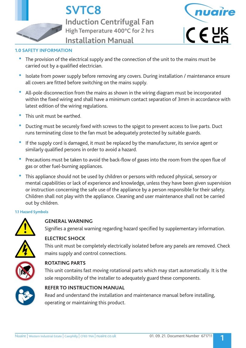
Brands
  1. Home
  2. •
  3. Brands
  4. •
  5. NuAire
  6. •
  7. Fan
  8. •
  9. NuAire DuctMaster DCB 315 Instruction Manual

NuAire DuctMaster DCB 315 Instruction Manual

NuAire Limited,
Western Industrial Estate,
Caerphilly, Mid Glamorgan,
CF83 1XH. United Kingdom.
Telephone: 02920 885911
Facsimile: 02920 887033
Email: [email protected]
Leaflet 670679
AUGUST 1999
Axial Flow Fans
DuctMaster
Circular Bifurcated
Installation
and Maintenance
Contents Page
Introduction / General Description
Dimensions
Installation
Silencer Information
Ancillaries Information
Fixing Details
Wiring Details
Spares & Service
1
.......
......................................
.......................................
..........................
.......................
...................................
...................................
................................
1
2
3
5
7
8
10
14
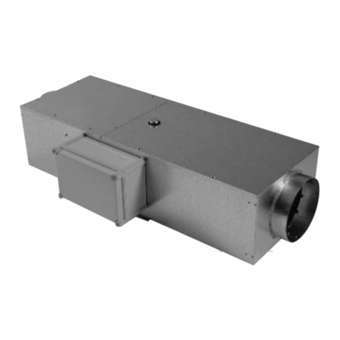
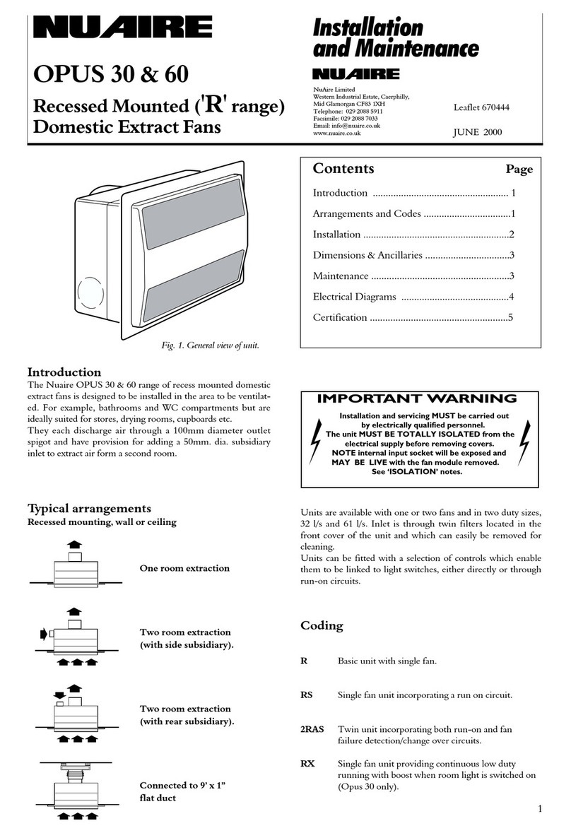
Fig. 1. General view of unit.
WARNING!
1. DO NOT REVERSE IMPELLER DIRECTION FOR OPERATION
AS THE PERFORMANCE OF THE UNIT IS DRASTICALLY
REDUCED (SEE START UP PROCEDURE).
2. DO NOT ALTER THE BLADE ANGLE OF THE IMPELLER
WITHOUT THE PERMISSION OF NUAIRE.
THE ABOVE MAY INVALIDATE YOUR WARRANTY
Introduction
The NuAire DuctMaster bifurcated range of Axial Flow
Fans are produced in seven case sizes from 315mm dia. to
630mm dia. with duties from 0.25m3/s to 5.25m3/s.
The units are available in standard or high temperature
types.
Impellers have been selected at 5 degree blade intervals
matched to various motor speeds to provide a range of
units that will suit your specific individual performance
requirements.
Blades are adjustable and can be reset to suit final system
resistances if necessary. However, we strongly recommend
that you contact NuAire before any blade angle changes
are undertaken.
NuAire will not accept responsibility for damaged units
when unauthorised personnel have altered blade angles.
Units are available for both single or three phase operation.
Some units are suitable for inverter speed control, contact
NuAire for full details.
NuAire DuctMaster Bifurcated fans have been tested to
BS 848 in our BSI approved laboratories. This ensures that
all technical data is accurate and that all units can be speci-
fied with confidence.
General Description
The DuctMaster Bifurcated range of Axial Flow Fans has
been designed specifically for ease of installation into new
or existing ductwork systems. Each fan is supplied complete
with two matching flanges, self sealing clamping collars
and four mounting feet with fixings. The fan casing
incorporates two integral, opposed, mounting pads.
Each pad has multiple fixing holes for the feet allowing
installation in any mounting plane.
Anti-vibration Mounting kits are available on request.
The case flanges mate with ductwork etc using single bolt
quickfit clamping collars.
A full range of ancillaries is available including matching
Silencers, Flexible Connectors, Wall Support Brackets and
Controls.
Many fans are fully compatible with Microsave and
conventional controls (For controls see Data Sheet Leaflet
No 670673 for full details).
Ductmaster models are also available polyester powder
painted for external use.
Dimensions (mm) Unit
Weight (kg)
Unit Code A B C D E F G 2 Pole 4Pole
DCB 315 310 360 433 369 298 265 168 22 22
DCB 350 345 395 433 427 339 265 168 25 25
DCB 400 395 445 500 442 384 218 168 31 28
DCB 450 445 475 500 514 424 319 168 38 32
DCB 500 493 545 605 555 488 326 168 49 43
DCB 560 553 605 606 633 565 278 168 - 43
(4 Pole)
DCB 560 553 605 606 633 527 418 168 55 -
(2 Pole)
DCB 630 622 674 651 729 615 428 168 - 65
(4 Pole)
DCB 630 622 674 651 751 619 468 168 84 -
(2 Pole)
Installation and Maintenance DUCTMASTERBIFURCATED
2
Fan Dimensions
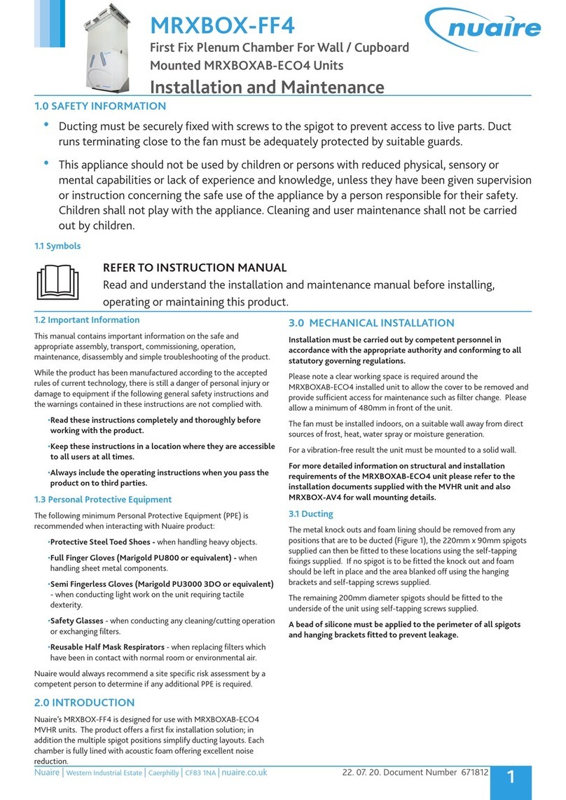
Four mounting feet are supplied with each
unit or silencer, see main fixing drawings.
M8 fixing screws are included.
Mounting Foot
65 25
50
48
90
75
F
E
D
C
A
BMatching
Flange
Clamping
Collar
Installation and Maintenance DUCTMASTERBIFURCATED
could be attached to the feet of the fan in order to determine
the ducting centreline relative to the mounting plane.
(Foot fixing centres are shown on fixing details drawing
which should allow the brackets to be pre fitted to the wall
ready to accept the fan assembly).
Consider the position of the fans electrical terminal box
when choosing an installation position.
Assuming that the position for mounting has been chosen.
and any wall brackets (if used) are already correctly located,
stand or support the unit in place and check the unit is
aligned with the ductwork in both horizontal and vertical
planes. A degree of adjustment is provided on the feet but it
may be necessary to pack up the height under the mounting
feet. See fixing details on page 9.
Mark on the floor / structure the fixing positions for the feet
or resilient mountings and if necessary drill suitable holes to
accept bolt or screw fixings (screws not supplied).
If matching silencers are to be installed, these should be
fitted to the fan with any other accessories such as flexible
connectors etc. before installation and the complete assembly
mounted in position using the same procedure.
The matching flanges if required on the installation are
fixed to the ductwork ends with rivets etc. Ensure the
clamping collars have been placed onto the ducting before
drawing the flanges together. Note: make sure the flange
faces are properly mated before fitting and tightening the
clamping collars.
Suspended horizontally or vertically
The only difference for suspension is in the positioning of
the mounting feet which are now fixed to the sides of the
mounting pads by the smaller single hole leg of the feet.
See fixing details on page 9.
If Resilient Mountings are to be included note that the
rubber mountings must remain in compression - this
involves fixing the rubber mounting upside down inside
the foot. The large metal safety washers must be fitted
under the studding nuts on each mounting. See Resilient
Mounting assembly (suspended) drawing on page 6.
General.
Motors are totally enclosed and protected to IP55 (Dust and
low pressure water jets). Motors may incorporate drain
holes to allow any condensation to escape from the motor
casing. It is essential therefore that these drain holes
are positioned at the lowest point of the fan motor
when the unit is horizontally mounted.
All bearings are pre-packed with grease and sealed for life.
3
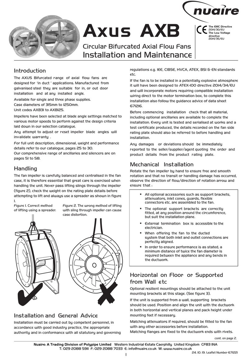
Handling
The DuctMaster fan impeller is carefully balanced prior
to despatch. Care must be taken on site when handling the
unit not to damage or distort the blades or alter the motor
position. Do not pass lifting slings etc through the impeller.
Always use the mounting pads (top or bottom) for sling
attachments.
The fan is supplied with installation accessories i.e. two
matching flanges, two clamping collars and four mounting
feet attached. These items are fitted before delivery to
ensure parts are not lost on site. If the optional flexible
connectors are specified these will be fitted for delivery to
the customer. However care must be taken when handling
the unit assembly as the flexibles can be distorted or damaged.
Installation
Application
Unit
For external use it is good practice that the unit is installed
so that the motor tunnel is horizontal. Also the unit will be
painted RAL9014 (grey) which is suitable for maximum
temperatures of 230oC.
For internal use it is good practice that the unit be installed
so that the motor tunnel is vertical for a horizontal airflow.
Prior to installation the impeller should be rotated by hand
to check for smooth rotation and that no transit damage has
occurred.
Horizontal on floor etc.
Before commencing work it will be necessary to remove the
clamping collars and loose flanges. Simply unscrew the
clamp nut using a suitable spanner.
Note: during installation, ensure that the flanges are mated
together correctly before tightening the clamps.
The position of the shakeproof washers on the foot
mountings is important as these washers are fitted to restrain
any longitudinal movement of the feet. See fixing details on
page 6 noting that you have a choice of two holes when
fitting the feet for floor mounting.
If the optional resilient mountings have been chosen these
should be attached to the unit feet at this stage. See Resilient
Mounting assembly (floor mtg) drawing on page 6.
Note that the large steel safety washers in the mounting kit
are not required for floor mounting and can be discarded.
Details of resilient mounting kit selection is shown in the
table on the same page.
If the optional wall support brackets are to be used they
Installation and Maintenance DUCTMASTERBIFURCATED
4
Accessory Installation
Flexible Connections - Care must be taken when
installing flexible connections to ensure that duct mis-
alignment is not corrected by the flexible connection.
Both duct misalignment and slack connections cause
unnecessary pressure losses in the system.
Anti-Vibration Mountings - Anti-vibration mounts
cannot be fitted to a fan unless there are flexible
connectors between the fan or fan silencer combination
casing and the ducting. On combination fan/silencer
installations only four foot mountings are used, see
fixing details on page 9.
Suspension mounts in particular should be adjusted on
the drop rods to carry an equal proportion of the total
fan weight when installed, as unevenly adjusted
mountings could carry a load greater than the design
condition.
Anti-Backdraught Dampers - Anti-Backdraught
Damper should be checked for transit damage prior to
installation. Damper blades should be open and closed
to ensure smooth operation.
Maintenance
Maintenance
NuAire recommends all products maintained in accor-
dance with the HVCA “Standard Maintenance
Specification for Mechanical Services in Buildings” -
Volume II Ventilating and Air Conditioning.
For guidance only
Due to the different periods of operation from the time
of installation and conditions of use, no rigid inspec-
tion and maintenance periods can be recommended.
We suggest,
therefore that the inspection and if necessary cleaning /
bearing check should be carried out at regular intervals
of a maximum of six months.
For a routine inspection, check the tightness of all nuts,
keys, grubscrews and endbolts etc. Remove any build
up of dirt or dust with a brush.
Connection details
Check that the voltage on the fan rating label is suitable
for your supply. Full load / starting currents are also
indicated.
The fan unit incorporates a terminal box on the motor
exterior. Units for external use require weatherproof
conduit and glands.
Motors up to and including 3kW are designed for Direct
On Line starting. Motors with outputs of 4kW and above
are suitable for Direct On Line or Star/Delta starting.
Flameproof motors are generally supplied for wiring
and connection, direct to the motor terminals, on site
by the installer (special wiring instructions must be
provided by NuAire). Connections and fittings used
must be in accordance with current BASEEFA approved
standards and requirements.
Motor overload protection should be set to the full load
current on the fan rating label. Supply fuses should be
H.R.C. type.
Start up procedure
When starting ensure that the impeller rotation follows
the label arrow indicator on the casing. Should the
direction be incorrect on three phase units, reverse any
two of the supply leads. See wiring diagrams pages 10.
(Do not reverse the impeller direction permanently).
Equipment should be run for approximately 30 minutes
to ensure correct operation. If any fault occurs, the
equipment should be switched off. Do not re-start until
the fault has been rectified.
DCS315S to DCS630S.
Short Un-podded.
DCS315L to DCS630L.
Long Un-podded.
DCSP315S to DCSP630S.
Short Podded.
DCSP315L to DCSP630L.
Long Podded.
Dimensions (mm) Weight (kg)
Unit A B C C D E F F Short Short Long Long
Code Short Long Short Long Podded No Pod Podded No Pod
DCS 315 310 410 374 684 450 355 230 230 11.0 7.0 17.0 13.0
DCS 350 345 445 409 754 510 355 230 230 14.0 10.0 24.0 17.0
DCS 400 395 495 459 854 540 405 230 230 16.0 12.0 29.0 22.0
DCS 450 445 545 509 954 600 405 230 230 23.0 19.0 37.0 30.0
DCS 500 493 643 557 1050 666 502 230 230 29.0 25.0 45.0 37.0
DCS 560 553 703 617 1170 726 565 230 230 32.0 29.0 47.0 40.0
DCS 630 622 772 686 1308 795 630 230 230 36.0 34.0 58.0 52.0
5
Installation and Maintenance DUCTMASTERBIFURCATED
Construction
NuAire DuctMaster attenuators for Bifurcated units
are manufactured with a rigidly constructed,
cylindrical galvanised steel casing. The casing is lined
internally with sound absorbent material which has
excellent acoustic properties, is non-hygroscopic and
also incombustible. The material is retained by a perfo-
rated aluminium liner.
Each silencer has two opposed mounting pads with
multiple mounting feet fixing points.
Flanges are quickfit type to match the DuctMaster
Bifurcated axial fans.
Four mounting feet, feet fixings and a clamping collar
are supplied with each silencer.
When a pod is fitted it is constructed of perforated
aluminium with an infill of the acoustic material.
Silencer Types
Two types of cylindrical silencer are available:
Unpodded : Ref = DCS
Podded : Ref = DCSP
(The introduction of the pod considerably improves
the attenuation but increases resistance to airflow).
Two standard lengths of silencers are available:
Short : Ref = S
Long : Ref = L
Examples:
a) DCSP 315 S is a short silencer with a pod.
b) DCS 315 L is a long silencer without a pod.
Silencers
Note:
Podded silencer
illustrated
B
A
C
F
E
D
Clamping
Collar
Installation and Maintenance DUCTMASTERBIFURCATED
6
DCB315
DCB350
DCB400
DCB450
DCB500
DCB560
DCB630
Shakeproof
washers.
Note: the 25mm
safety washers are
only required for
‘suspended’
applications.
Shakeproof
washers. Nuts used for
height adjustment.
DAV1 = 30
DAV2-6 =40
DAV1 = 30
DAV2-6 =40
DAV1 = 50
DAV2 - 6 =75
DAV1 = 50
DAV2-6 =75
Fixings by
installer.
Mounting pad
upon unit.
Mounting pad
upon unit.
Resilient mounting
kit c/w fixings
(four supplied).
Four mounting feet c/w fixings
(supplied with unit).
Four mounting feet c/w
fixings (supplied with unit).
Thread insert.
DAV1 = M8
DAV2-6 = M10/M12
Thread insert.
DAV1 = M8
DAV2-6 = M10/M12
25mm dia safety washer (four 25mm
washers supplied essential for safety
supplied with kit), other fixings by installer.
DAV1
DAV2
DAV2
DAV2
DAV2
DAV2
DAV2
DAV2
DAV2
DAV2
DAV2
DAV5
DAV5
DAV5
2 & 4
2 & 4
2
4
2 (10O-20O)
2 (21O-25O)
4
2
4
2
4
2 (10o)
2 (12o-15o)
4
DAV2
DAV2
DAV2
DAV2
DAV2
DAV2
DAV2
DAV5
DAV5
DAV5
DAV5
DAV5
DAV5
DAV5
DAV2
DAV2
DAV2
DAV2
DAV2
DAV2
DAV2
DAV5
DAV2
DAV5
DAV2
DAV5
DAV5
DAV5
DAV2
DAV2
DAV2
DAV2
DAV5
DAV5
DAV5
DAV5
DAV5
DAV5
DAV5
DAV5
DAV3
DAV5
DAV2
DAV2
DAV2
DAV2
DAV5
DAV5
DAV2
DAV5
DAV5
DAV5
DAV5
DAV5
DAV3
DAV5
DAV2
DAV2
DAV2
DAV2
DAV5
DAV5
DAV2
DAV5
DAV5
DAV5
DAV5
DAV5
DAV3
DAV5
DAV2
DAV2
DAV2
DAV2
DAV2
DAV2
DAV2
DAV5
DAV5
DAV5
DAV5
DAV5
DAV3
DAV5
DAV5
DAV5
DAV5
DAV5
DAV5
DAV5
DAV5
DAV5
DAV5
DAV5
DAV5
DAV3
DAV3
DAV3
DAV2
DAV2
DAV5
DAV5
DAV5
DAV5
DAV5
DAV5
DAV5
DAV5
DAV5
DAV3
DAV3
DAV5
Resilient Mounts
The above anti vibration mountings are available for the
DuctMaster Bifurcated range of axial flow fans.
See selection table opposite.
Kits are supplied for unit or unit silencer combinations
and comprise the requisite number of resilient mounts
for 'floor' or 'suspension' use (see details above).
65 25
50
48 90
75
35
33 5
M8
Fixings
supplied
Mounting Foot details
Resilient Mounting ‘Floor’ fixing Resilient Mounting ‘Suspended’ fixing
Mounting Foot Notes
Four mounting feet are supplied with each unit or
silencer, see main dimension drawings. M8 fixing screws
are included.
Note: See fixing details, page 9.
.
.
.
...
.
.
.
.
Unit
Code
Resilient mounting kit (selection)
Unit
Motor
Poles
(kw)
Unit
Only Unit Plus
One Short
Silencer
Pod No Pod
Unit Plus
Two Short
Silencers
Pod No Pod
Unit Plus
One long
Silencer
Pod No Pod
Unit Plus
Two long
Silencers
Pod No Pod
Manufactured in heavy gauge galvanised
steel with a single quickfit flange.
Standard Accessory Losses (k)
Low loss
inlet cone 0.38
Flat type
Finger guard 0.75
CODES: DCIC 315 (typical)
DCIG 315 (typical)
with wire guard
Dimensions (mm)&Weights
Dia.mm A B C Weight(Kg)
315 310 400 70 2
350 345 450 70 2
400 395 510 85 3
450 445 570 95 4
500 493 640 105 5
560 553 715 115 6
630 622 800 125 9
Gravity operated damper to prevent back-
draughts. Manufactured in heavy gauge
galvanised steel with a pair of quickfit
flanges
Standard Accessory Losses (k)
(Airstream 0.4
operated)
CODES: DCBD 315 (typical)
Dimensions (mm)&Weights
Dia.mm A B C Weight(Kg)
315 310 333 360 7.5
350 345 333 360 9.0
400 395 333 360 11.0
450 445 333 360 14.0
500 493 333 390 16.5
560 553 333 420 20.0
630 622 333 450 22.5
A set of AVs are matched to the unit or
unit /silencer combination.
The resilient mounts supplied for use
with the DuctMaster range are suitable for
use in floor mounted or hanging type
applications.
Note: A/V Kits DAV 7 and above are
combinations of the above.
CODES: DAV (typical)
Dimensions (mm)
Code A B
DAV 1 30 50
DAV 2 40 75
DAV 3 40 75
DAV 4 40 75
DAV 5 40 75
DAV 6 40 75
Circular with a single quickfit flange.
Flexibleductmaterialisflameproof
and resistant to chemicals, ozone, oil, grease
and heat up to 900C & 2300C (see codes).
Thespigotisoflight gaugegalvanisedsteel.
The connector is airtight, waterproof and
testedtoBS476Part7.
CODES: DCFX 315
(typical 900C)
DCFH 315
(typical 2300C)
Dimensions (mm)
Nom. Dia A B C
315 310 50 168
350 345 50 168
400 395 50 168
450 445 50 168
500 493 50 168
560 553 50 168
630 622 50 168
Installation and Maintenance DUCTMASTERBIFURCATED
7
Flexible Connectors
Resilient Mountings
Backdraught Dampers
Inlet Cone
(wire guard optional)
R ili M i
C
B
A
A
B
C
A
B
C
B
A
Optional
Wire Guard
Note:
Mounting feet
supplied with
fan unit
Ancillaries
Details shown are for units up to 90oC
Hot dipped galvanised for either inlet or out-
let fixing. Fitted with a single quickfit flange.
Standard Accessory Losses (k)
Flat type
Finger guard 0.75
CODES: DCGD 315 (typical)
Dimensions (mm) &Weights
Dia. mm A B Weight (Kg)
315 310 30 0.5
350 345 30 0.9
400 395 40 1.5
450 445 45 1.7
500 493 45 2.3
560 553 45 2.8
630 622 45 3.2
Wire Guards
Quickfit to Bolted
flange connector
A
B
To convert a quick fit flange to a bolted flange.
Manufactured from heavy gauge galvanised
steel.
CODES: DCQB315 (typical)
Dimensions (mm)&Weights
Dia. mm A B C Weight(Kg)
315 310 375 45 1.2
350 345 421 45 1.2
400 395 475 55 1.9
450 445 520 55 1.9
500 493 585 60 3.2
560 553 645 60 4.6
630 622 715 60 5.0
AC
B
8
Suspended horizontally from above.
Suspended vertically from above.
AB
A1 B
B1
View on ‘Y’ View on ‘Z’
End view Side view
End view Side view
F
‘Z’
‘Y’
DCB315 2 & 4
DCB350 2 & 4
DCB400 2 & 4
DCB450 2 & 4
DCB500 2 & 4
DCB560 4
DCB560 2
DCB630 4
DCB630 2
DCB630 2
298
339
384
424
484
562
530
616
596
596
348
389
434
474
534
612
580
666
646
646
265
266
218
319
294
256
256
391
391
391
188
229
274
314
374
452
420
506
486
486
656
675
708
784
830
841
841
943
943
943
811
847
905
1003
1076
1117
1117
1254
1254
1254
355
355
405
405
502
565
565
630
630
630
405
405
455
455
552
615
615
680
680
680
469
527
542
614
653
732
732
825
825
825
483
518
568
618
716
776
776
845
845
845
243
243
293
293
393
453
453
523
523
523
230
230
230
230
230
230
230
230
230
230
M8/M10
M8/M10
M10
M10
M10
M10
M10
M10
M10
M10
1041
1077
1194
1244
1362
1422
1422
1490
1490
1490
1351
1421
1588
1682
1854
1974
1974
2112
2112
2112
Unit
Code Dimensions (mm) between foot fixing hole centres
short
silencer long
silencer short
silencer long
silencer
Drop**
rods and
bolt sizes
for AV
mounts
A A1 B B1 C C D D1 E E F G H J J
short
silencer long
silencer
230
230
230
230
230
230
230
230
230
230
Dimensions of fixing centres
Supported horizontally from floor.
Fixing Details Unit only
Installation and Maintenance DUCTMASTERBIFURCATED
9
Unit + one silencer Unit + two silencers
D
C
BJ
BJD1
Side elevations
C
Side elevations
G
E
BJ
J
E
BJ
J
Part end view
(Silencer only)
Part end view
(Silencer only)
View on ‘X’
‘X’
HG
Side elevations
Silencer
Silencer
Unit
NOTE:
Outer mountings only
required on units up to 630.
Additional mounts for
heavier units shown shaded.
Call NuAire for full details.
NOTE:
4 Drop rods only required on
units up to 630. Additional rod
positions are shown shaded.
INSTALLATION NOTES:
For internal use it is good practice that the unit be
installed so that the motor ‘tunnel’ is vertical to
provide a natural vertical movement of air cooling
the motor. In this attitude, the mounting feet
would be fixed to the mounting pad ‘faces’.
For external use it is good practice that the unit be
installed with the motor ‘tunnel’ horizontal. In
this attitude, the mounting feet be would fixed to
the mounting pad sides.
Installation and Maintenance DUCTMASTERBIFURCATED
10
Electrical Information
Wiring Details
MICROSAVE Controls
DuctMaster Bifurcated is compatible with Microsave Starters
and Speed Controls:
SEE INSIDE REAR COVER For further details refer to:
Microsave/Masterclass Selection Guide Leaflet No. 670588 and
Technical Data Sheet Nos. 670578 ‘Speed Controls’ 670579 ‘Starters’.
For Microsave wiring information please refer to :
Microsave Starter controls Leaflet No. 670579
Microsave Speed controls Leaflet No. 670578
3 PHASE FOR D.O.L. STARTING
400V 3 phase 50Hz supply
Incoming
three phase
supply
U1
V1
W1
Motor
terminal
box
Incoming
single phase
supply
1 PHASE SINGLE SPEED
U1
U6
L
N
230V 1 phase 50Hz supply
Motor
terminal
box
2 SPEED TAP/ PAM WOUND MOTOR
(D.O.L. starting both speeds)
400V 3 phase 50Hz supply
1U
1V
1W
2U
2V
2W
Motor
terminal
box
NOTE:
LOW SPEED - Supply: 1U 1V 1W
HIGH SPEED - Supply: 2U 2V 2W
LINK 1U 1V 1W
3 Phase for Star / Delta starting
(4kW and above)
U1
V1
W1
W2
U2
V2
STAR
L1 - U1
L2 - V1
L3 - W1
Link W2, U2, V2
DELTA
L1 - U1 - W2
L2 - V1 - U2
L3 - W1 - V2
Installation and Maintenance DUCTMASTERBIFURCATED
Speed Controls, Starters & Isolators (see easy selection tables) Dimensions(mm)
Depth
Height
Width
Unit type or code Transformer speed controls Isolators Starters MicroSave controls
SP CON 4
SP CON 5
SP CON 6
SP CON 7
3SP CON 1
3SP CON 1A
3SP CON 2
3SP CON 4
3SP CON 7
DMISOL
(all units)
STAR
(all units)
Interface
control panel
for starters &
Speed controls
(all units).
75
140
315
105
185
315
105
185
315
110
255
190
110
253
188
110
253
188
110
253
188
135
309
262
135
309
262
90
135
95
47
148
88
37
87
147
11
We declare that the machine named below
conforms to the requirements of EC Council Directives
relating to Electromagnetic Compatibility and
Safety of Electrical Equipment.
Designation of machinery :- DUCTMASTE BIFURCATED FAN
Machinery Types :- DCB
Relevant EC Council Directives :- 89/336/EEC, 92/31/EEC (EMC)
73/23/EEC, 93/68/EEC (Low Voltage Directive)
Applied Harmonised Standards :- E50081-1, EN50082-1, EN60204-1
EN60335-2-80
Basis of Self Attestation :- Quality Assurance to BS EN ISO 9001
BSI Registered Firm Certificate No. FM 149
Signature of manufacture representatives :-
Name: Position: Date:
1) C. Biggs Technical Director 2. 4. 98
2) M. Fussell Manufacturing Director 2. 4. 98
NuAire Limited,
Western Industrial Estate,
Caerphilly, Mid Glamorgan,
CF83 1XH. United Kingdom.
Telephone: 01222 885911
Fax: 01222 887033
Email: info @ nuaire.co.uk
Leaflet
OCTOBER 1998
DECLARATION
OF CONFORMITY
12
We declare that the machinery named below is intended to be assembled with other
components to constitute a system of machinery.
The machinery shall not be put into service until the system has been declared to be
in conformity with the provisions of the EC Council Machinery Directive.
Designation of machinery :- DUCTMASTER BIFURCATED FAN
Machinery Types :- DCB
Relevant EC Council Directives :- 98/37/EC (Machinery Directive)
93/44/EEC (Amendment to the Machinery Directive)
Applied Harmonised Standards :- EN292-1, EN292-2, EN294, EN29001
Applied National Standards :- BS848 Parts One, Two and Five
Signature of manufacture representatives :-
Name: Position: Date:
1) C. Biggs Technical Director 3.1.98
2) M. Fussell Manufacturing Director 3.1.98
NuAire Limited,
Western Industrial Estate,
Caerphilly, Mid Glamorgan,
CF8 1XH. United Kingdom.
Telephone: 01222 885911
Fax: 01222 887033
Email: info @ nuaire. co. uk
0CTOBER 1998
DECLARATION OF INCORPORATION
& INFORMATION FOR SAFE
INSTALLATION, OPERATION & MAINTENANCE
13
INFORMATION FOR SAFE INSTALLATION, OPERATION
AND MAINTENANCE OF NUAIRE VENTILATION EQUIPMENT
To comply with EC Council Directives 89/392/EEC Machinery Directive
& 93/44/EEC Amendment to the Machinery Directive.
To be read in conjunction with the relevant Product Documentation (see 2.1)
1.0 GENERAL
1.1 The equipment referred to in this Declaration of Incorporation is supplied by NuAire to be assembled into a ventilation
system which may or may not include additional components.
The entire system must be considered for safety purposes and it is the responsibility of the installer to ensure that all of the
equipment is installed in compliance with the manufacturers recommendations and with due regard to current legislation and
codes of practice.
2.0 INFORMATION SUPPLIED WITH THE EQUIPMENT
2.1 Each item of equipment is supplied with a set of documentation which provides the information required for the safe installation
and maintenance of the equipment. This may be in the form of a Data sheet and/or Installation and Maintenance instruction.
2.2 Each unit has a rating plate attached to its outer casing. The rating plate provides essential data relating to the equipment such as
serial number, unit code and electrical data. Any further data that may be required will be found in the documentation. If any
item is unclear or more information is required, please contact NuAire.
2.3 Where warning labels or notices are attached to the unit the instructions given must be adhered to.
3.0 TRANSPORTATION, HANDLING AND STORAGE
3.1 Care must be taken at all times to prevent damage to the equipment. Note in particular that shock to the unit may result in the
balance of the impeller being affected.
3.2 When handling the equipment, care should be taken with corners and edges and that the weight distribution within the unit is
considered. Lifting gear such as slings or ropes must be arranged so as not to bear on the casing.
3.3 Equipment stored on site prior to installation should be protected from the weather and steps taken to prevent ingress of
contaminants.
4.0 OPERATIONAL LIMITS
4.1 It is important that the specified operational limits for the equipment are adhered to e.g. operational air temperature, air borne
contaminants and unit orientation.
4.2 Where installation accessories are supplied with the specified equipment eg. wall mounting brackets. They are to be used to
support the equipment only. Other system components must have separate provision for support.
4.3 Flanges and connection spigots are provided for the purpose of joining to ductwork systems. They must not be used to support
the ductwork.
5.0 INSTALLATION REQUIREMENTS
In addition to the particular requirements given for the individual product, the following general requirements should be noted.
5.1 Where access to any part of equipment which moves, or can become electrically live are not prevented by the equipment panels
or by fixed installation detail (eg ducting), then guarding to the appropriate standard must be fitted.
5.2 The electrical installation of the equipment must comply with the requirements of the relevant local electrical safety regulations.
6.0 COMMISSIONING REQUIREMENTS
6.1 General pre-commissioning checks relevant to safe operation consist of the following -
Ensure that no foreign bodies are present within the fan or casing
Check electrical safety. e.g. Insulation and earthing.
Check guarding of system.
Check operation of Isolators/Controls.
Check fastenings for security.
6.2 Other commissioning requirements are given in the relevant product documentation.
7.0 OPERATIONAL REQUIREMENTS
7.1 Equipment access panels must be in place at all times during operation of the unit, and must be secured with the original fastenings.
7.2 If failure of the equipment occurs or is suspected then it should be taken out of service until a competent person can effect repair
or examination. (Note that certain ranges of equipment are designed to detect and compensate for fan failure).
8.0 MAINTENANCE REQUIREMENTS
8.1 Specific maintenance requirements are given in the relevant product documentation.
8.2 It is important that the correct tools are used for the various tasks required.
8.3 If the access panels are to be removed for any reason the electrical supply to the unit must be isolated.
8.4 A minium period of two minutes should be allowed after electrical disconnection before access panels are removed. This will allow
the impeller to come to rest.
NB: Care should still be taken however since airflow generated at some other point in the system can cause the impeller to “windmill” even when
power is not present.
8.5 Care should be taken when removing and storing access panels in windy conditions.
14
Spares
In view of the fact that the product incorporates sealed
for life bearings and utilises no consumables we would
not recommend a stock holding of spares.
In the unlikely event that a failure should occur contact
our service department and quote the fan rating label
details.
Service
As a manufacturer NuAire provides you with factory
trained Service Engineers.
Our Engineers are supported by a comprehensive range
of spare parts 'off the shelf'.
If you are an industrial or commercial user, you may be
interested in details of NuAire's regular maintenance
Service Contracts. This is a worthwhile service that
helps you get the most from our products.
Our Service Department will be happy to give you
more information.
Please Telephone: 01222 858271
3 YEAR WARRANTY
The three year warranty starts from the date of delivery and
includes parts and labour for the first year.
The labour element is subject to full, free and safe access to the
equipment as recommended by the CDM regulations.
The remaining two years covers replacement parts only.
NOTE:
Installation & Maintenance of the equipment must be as
directed in the instructions provided with the unit.
Controls Application Service (CAS)
A team of Engineers and technicians is available to provide pre and
post order support.
We are on hand to provide help and advice from the most basic use
of any NuAire equipment to the more complex applications, max-
imising on the versatility of our SMART and NetLink
control products.
Telephone: 01222 858585
Facsimile: 01222 858586
WARNING!
1. DO NOT REVERSE IMPELLER DIRECTION FOR
OPERATION AS THE PERFORMANCE OF THE UNIT
IS DRASTICALLY REDUCED.
2. DO NOT ALTER THE BLADE ANGLE OF THE
IMPELLER WITHOUT THE PERMISSION OF NUAIRE.
THE ABOVE MAY INVALIDATE YOUR WARRANTY
Installation and Maintenance DUCTMASTERBIFURCATED
15
NB
If you have any comments or
queries on any of our products or
services please write to the
Marketing Services Manager at the
main address above.
Western Industrial Estate, Caerphilly,
Mid Glam CF8 1XH United Kingdom.
Telephone: 02920 885911
Facsimile: 02920 887033
Leaflet No. 670679
Technical or commercial considerations may, from time to time,
make it necessary to alter the design, performance and dimensions
of equipment and the right is reserved to make such changes
without prior notice.
Installation and Maintenance DUCTMASTERBIFURCATED
16

This manual suits for next models

7

Other NuAire Fan manuals

NuAire Ecosmart Squrbo Series Instruction Manual

NuAire

NuAire Ecosmart Squrbo Series Instruction Manual

NuAire NA-E-150 Series Instruction Manual

NuAire

NuAire NA-E-150 Series Instruction Manual

NuAire HPKF Instruction Manual

NuAire

NuAire HPKF Instruction Manual

NuAire MRXBOX-ECO Series User manual

NuAire

NuAire MRXBOX-ECO Series User manual

NuAire XS Series Instruction Manual

NuAire

NuAire XS Series Instruction Manual

NuAire lpXboxac Instruction Manual

NuAire

NuAire lpXboxac Instruction Manual

NuAire Genie-DC Series Instruction Manual

NuAire

NuAire Genie-DC Series Instruction Manual

NuAire ES-OPUSDC 40-M Instruction Manual

NuAire

NuAire ES-OPUSDC 40-M Instruction Manual

NuAire Neonaire NE20T User manual

NuAire

NuAire Neonaire NE20T User manual

NuAire Genie/tops M in-line Instruction Manual

NuAire

NuAire Genie/tops M in-line Instruction Manual

NuAire AXUS SVT Series Instruction Manual

NuAire

NuAire AXUS SVT Series Instruction Manual

NuAire XBOXER Instruction Manual

NuAire

NuAire XBOXER Instruction Manual

NuAire MRXBOX95B-WHIH Instruction Manual

NuAire

NuAire MRXBOX95B-WHIH Instruction Manual

NuAire MRXBOXAB-ECO2B-1Z User manual

NuAire

NuAire MRXBOXAB-ECO2B-1Z User manual

NuAire MRXBOX-ECO3-1Z User manual

NuAire

NuAire MRXBOX-ECO3-1Z User manual

NuAire mrXbox70 Instruction Manual

NuAire

NuAire mrXbox70 Instruction Manual

NuAire MRXBOX-ECO2-1Z User manual

NuAire

NuAire MRXBOX-ECO2-1Z User manual

NuAire ES-OPUSDC Series User manual

NuAire

NuAire ES-OPUSDC Series User manual

NuAire ecosmart MEV-DC Instruction Manual

NuAire

NuAire ecosmart MEV-DC Instruction Manual

NuAire NE25BTX User manual

NuAire

NuAire NE25BTX User manual

NuAire MRXBOX95B-LH1 User manual

NuAire

NuAire MRXBOX95B-LH1 User manual

NuAire ECOSMART TWINFANS EST-X Guide

NuAire

NuAire ECOSMART TWINFANS EST-X Guide

NuAire MRXBOX95B-WM2 Instruction Manual

NuAire

NuAire MRXBOX95B-WM2 Instruction Manual

NuAire ECOSMART AIRMOVER Instruction Manual

NuAire

NuAire ECOSMART AIRMOVER Instruction Manual

Popular Fan manuals by other brands

Bionaire BW2300 Instruction leaflet

Bionaire

Bionaire BW2300 Instruction leaflet

Craftmade American Tradition AT52ET Specifications

Craftmade

Craftmade American Tradition AT52ET Specifications

Sabiana Ventil Carisma Fly CVP-ECM manual

Sabiana

Sabiana Ventil Carisma Fly CVP-ECM manual

Korona 81010 instruction manual

Korona

Korona 81010 instruction manual

STIEBEL ELTRON LWZ 504 Operation

STIEBEL ELTRON

STIEBEL ELTRON LWZ 504 Operation

BLAUBERG Ventilatoren Wind Series Service instruction

BLAUBERG Ventilatoren

BLAUBERG Ventilatoren Wind Series Service instruction

VALBERG BITH 60 X 756C Instructions for use

VALBERG

VALBERG BITH 60 X 756C Instructions for use

Vaillant 009730 installation manual

Vaillant

Vaillant 009730 installation manual

U.S. FAN UVQL100 quick start guide

U.S. FAN

U.S. FAN UVQL100 quick start guide

Progress Lighting AirPro P2548 installation manual

Progress Lighting

Progress Lighting AirPro P2548 installation manual

emerio FN-109082 instruction manual

emerio

emerio FN-109082 instruction manual

Unold BREEZY SWING Instructions for use

Unold

Unold BREEZY SWING Instructions for use

Bionaire BASF40B instruction manual

Bionaire

Bionaire BASF40B instruction manual

Poujoulat RENOSHUNT installation instructions

Poujoulat

Poujoulat RENOSHUNT installation instructions

Bauer 1959C-B user manual

Bauer

Bauer 1959C-B user manual

Sulion 075155 manual

Sulion

Sulion 075155 manual

Hunter Dempsey Accessories guide

Hunter

Hunter Dempsey Accessories guide

Hunter Eurus Owner's guide and installation manual

Hunter

Hunter Eurus Owner's guide and installation manual

manuals.online logo
manuals.online logoBrands
  • About & Mission
  • Contact us
  • Privacy Policy
  • Terms and Conditions

Copyright 2025 Manuals.Online. All Rights Reserved.