manuals.online logo
Brands
  1. Home
  2. •
  3. Brands
  4. •
  5. NuAire
  6. •
  7. Fan
  8. •
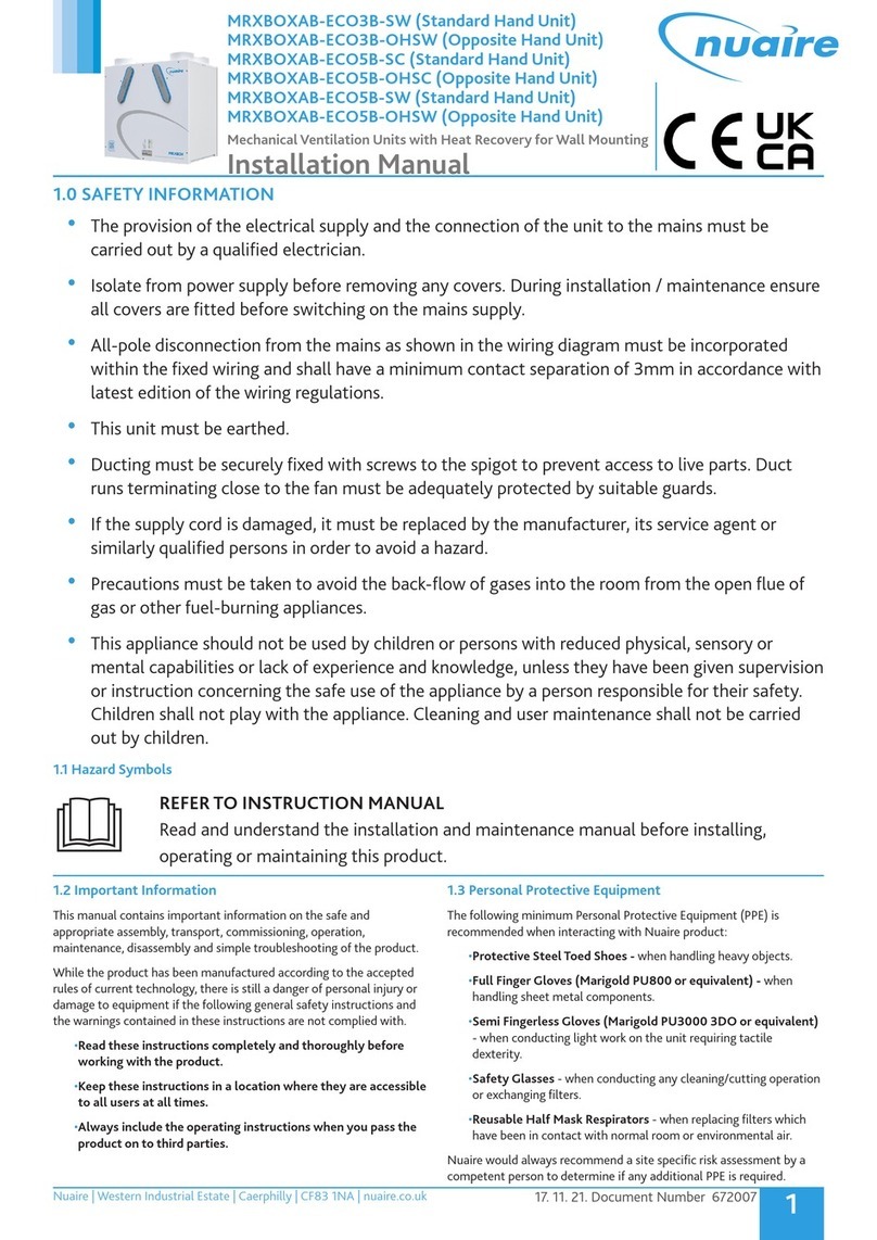
  9. NuAire mrXbox70 Instruction Manual

NuAire mrXbox70 Instruction Manual

Nuaire Limited Western Industrial Estate Caerphilly United Kingdom CF83 1NA
T: 029 2088 5911 F: 029 2088 7033 E: [email protected] W: www.nuaire.co.uk
1Leaflet Number 671365 October 2009
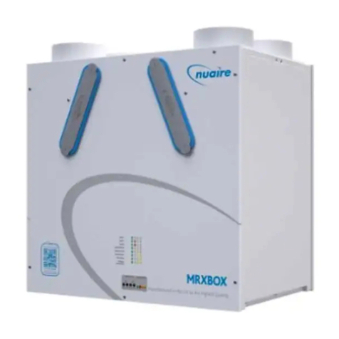
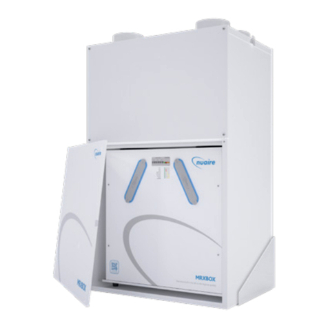
mrXbox70
Mechanical Ventilation
with Heat Recovery
Installation and Maintenance
Figure 2. Fixing the unit to the wall.
Figure 1.
Two mounting
bracket tongues
engage with slots
in top edge of unit
casing.
Align bottom of
mounting bracket
to engage with the
fixing screw holes
on the base of the
unit.
Bracket
tongues
fixing screw holes are
located in base of unit.
Figure 4.
Cut through the
acoustic foam round
the circumference of
the damper.
Damper can be
swivelled on the
2 body casing
hinges.
Figure 5.
When spigot is in
position, damper can
be adjusted using a
screwdriver.
1.0 Introduction
mrXbox70 is designed to provide mechanical supply and
extract ventilation with heat recovery.
The unit is fitted with two independent fans. Each fan has
full speed control for background and boost ventilation
rates as well as a run-on timer facility. To recover heat
from the extract air an aluminium heat exchanger block is
utilised. This heat exchanger can recover over 70% of the
normally wasted heat.
2.0 Installation
Installation must be carried out by competent personnel in
accordance with the appropriate authority and conforming
to all statutory governing regulations.
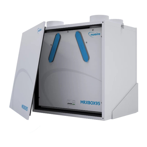
Please note a clear working space is required around the
installed unit to allow the cover to be removed and provide
sufficient access for maintenance such as filter change.
The fan must be installed indoors, away
from any direct sources of heat, water
spray or moisture generation.
Temperature range –5 to 40OC.
The unit is designed for wall mounting only.
The integral mounting bracket should be
offered up to the wall and the fixing points
marked through and the bracket installed
with 4 screws (by others). (figure 2).
To aid installation the case is split into
two halves. To split the case firstly remove
the front cover. Remove the four lower
screws and loosen the top two.
The top section can now be removed. The
rear section can be offered up to the
bracket and secured with the two screws
(see figure 3).
Note: Carry out all required electrical connections
before fitting the front section. Refer to section 4.0.
Various damper/inlet spigot positions can be utilised as
required to suit the system ductwork and extract grilles.
All inlet dampers are ’closed’ as knockouts when delivered
but can be opened using a sharp knife. (See figure 4).
After the spigot has been fixed adjust the damper with a
screwdriver. (See figure 5). Fit front section and secure
with screws previously removed/loosened.
See figures 6 and 8 for spigot location and sizes.
Figure 3.
The EMC Directive
2004/108/EC
The Low Voltage
directive
2006/95/EC
Any air intake terminal MUST be installed in accordance
with the appropriate regulation.
As a guide, the BS5440 series of British Standards
deals with this issue and currently states that an air
intake must be at a minimum distance of 300mm from a
gas boiler balanced flue. Installers are advised to be
aware of the requirements of this standard when
installing ‘through the wall’ supply air ducting.
Similarly, supply and extract air grilles should be
at least 300mm apart.
2Leaflet Number 671365 October 2009
Installation and Maintenance mrXbox70 Mechanical Ventilation with Heat Recovery
1. Mounting bracket.
2. Unit motor pod.
3. Heat exchanger pod.
Figure 6. Main unit components.
4. Heat exchanger.
Four smooth operating runners located on each
corner of the heat exchanger provide sealing and
ease of removal.
5. Access cover.
595
485
637
Bracket
fixing
VIEW FROM FRONT WITH COVER REMOVED SIDE VIEW MOUNTING BRACKET FRONT VIEW
Mounting bracket
340
250
4 holes
7.5mm dia.
3 x side spigot
knockouts
100mm dia.
6 x top spigot
knockouts
2 x 100mm dia.
4 x 125mm dia.
3 x side
spigot
knockouts
100mm dia.
VIEW FROM TOP Mounting bracket
153
26 4
78
9
Condensate Drain
Terminator
Block
Condensate Tray
3.0 Dimensions
Figure 8. Dimensions in mm.
Installation cont.
Before the unit is used
A bead of silicone is to be
applied along the edge
between the drip tray and
the heat exchanger.
This is to prevent any
water from running down
between the drip tray and
the heat exchanger. If this
seal is broken at any time in
the future then it must be
resealed with silicone. The fixing screw in the drip
tray must also be sealed with silicone.
Condensate Drain
The condensate drain tube protrudes from the
base of the unit (see figure 8). The condensate
should be disposed of via a water
trap connection to the outside of
the property or connected to
the house sewage system.
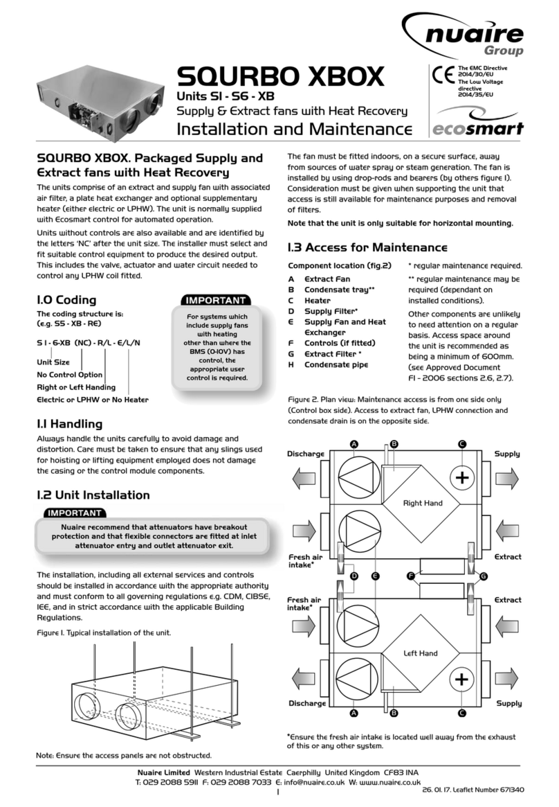
Spigot location and
airflow:
Supply air to house -
spigots 1, 5, and 7.
Extract air to outside -
spigot 3.
Fresh air from outside -
spigot 4.
Extract from kitchen/
bathroom etc -
spigots 2, 6, 8 and 9.
1 5
3
7
9
8
26
4
Figure 7.
Unit must not be switched off, product is
designed to run continuously.
For good EMC engineering practice, any sensor cables
or switched live cables should not be
placed within 50mm of other cables or on the same
metal cable tray as other cables.
Isolation - Before commencing work make sure that the unit,
switched live and Nuaire control are electrically isolated
from the mains supply. Note this product must be earthed.
Carry out all required electrical connections before fitting
the front section.
3Leaflet Number 671365 October 2009
Installation and Maintenance mrXbox70 Mechanical Ventilation with Heat Recovery
4.0 Electrical Wiring
The unit is designed to be wired directly to the mains supply
through a fused spur isolator (by others). With the rear
section only fixed in position bring the mains wiring through
the supplied cable gland (this gland can be moved to the
side position if required).
Additional grommeted holes are provided to allow additional
wiring to each blower.
The two fans are pre-wired into an internal wiring block for
ease of connection. (see figure 9 for connection details).
All incoming mains connections must be routed through a
suitable local isolator for maintenance purposes.
L
NFuse 3A max.
230V ac
signal
must be
routed
through
isolator
2
1
L
N
E
Signal to
activate
supply fan
Signal to
activate
extract fan
230V
50Hz
mains
supply
Isolator (by others)
Figure 9. Terminal Block Connections.
5.0 Setting to Work
Each fan is factory set to operate at trickle airflow when
power is applied and switch over to the boost flow rate
when a switched live signal is present. The pot marked ‘MIN
Airflow’ adjusts the trickle flow rate and the boost flow rate
by the pot marked ‘MAX Airflow’. These flow rates for the
supply and extract fan are adjusted separately. When the
switched live signal is removed, the fan will continue to run
at boost flow rate for a preset period as dictated by the pot
marked ‘RUN-on’.
6.0 Run-on Timer
The Run-on timer adjustment is from 0 - 60 mins. Run-on is
only available from the switched live (SL) signal.
7.0 Maintenance
It is inevitable that even with filtered extract grilles as
recommended in BRE digest 398 some dust, fluff etc. will
pass through the filter, and which, if allowed, will build up
internally on motors and impellers, shortening the life of
the unit and, in severe cases, leading to overheating of the
motors. Consequently, it is strongly recommended that all
units are inspected and cleaned every 18 months.
8.0 Cleaning
Remove covers and carefully clean out interiors as
necessary. To clean the filters, remove from the unit and
vacuum clean or wash in tepid water to which a little
detergent has been added. Shake out excess water and
allow to dry naturally. Replace when dry. The heat exchanger
core can be safely cleaned in a domestic dish washer.
Check for damage and security of components. Refit covers.
9.0 Replacement of Parts
Should any component need replacing Nuaire keep extensive
stocks for quick delivery. Ensure that the unit is electrically
isolated, before carrying out any work.
When ordering spare parts, please quote the serial number
of the unit and the ARC number of the purchase if possible.
(This information will be available on the fan label).
10.0 Warranty
The 5 year warranty starts from the day of delivery and
includes parts and labour for the first year and parts only
for the remaining 4 years. This warranty is conditional on
planned maintenance being undertaken.
11.0 Service Enquiries
Nuaire can assist you in all aspects of service. Our service
department will be happy to provide any assistance required,
initially by telephone and If necessary arrange for an
engineer to call.
Customer Services Department
on 08705 002 555
N
L
SL
Do not use
To OPUS-SPD
speed control
Internal
humidity adj.
To remote
fail indicator
ES-MEV-AVI
TEST
Status
30
0
60
Run-on
(mins)
25
100
Max
Airflow
(%)
25
100
Min
Airflow
(%)
LVT NET TR
240V 1ph
supply
pre-wired
to terminal
box
Switch live
input
pre-wired
to terminal
block
(Terminal 1 for extract fan)
(Terminal 2 for supply fan)
4.1 Additional Control Wiring Option
Other control wirings are available on each fan. Open the
cover of the unit to gain access to these connections on
each fan (see figure 10).
Figure 10.
4Leaflet Number 671365 October 2009
Technical or commercial considerations may, from time to time, make it necessary to alter the design, performance and
dimensions of equipment and the right is reserved to make such changes without prior notice.
DECLARATION OF INCORPORATION AND INFORMATION FOR SAFE INSTALLATION,
OPERATION AND MAINTENANCE
To comply with EC Council Directives 98/37/EC Machinery Directive and
2004/108/EC (EMC).
To be read in conjunction with the relevant Product Documentation (see 2.1)
1.0 GENERAL
1.1 The equipment referred to in this Declaration of Incorporation is supplied by
Nuaire to be assembled into a ventilation system which may or may not include
additional components.
The entire system must be considered for safety purposes and it is the
responsibility of the installer to ensure that all of the equipment is installed in
compliance with the manufacturers recommendations and with due regard to
current legislation and codes of practice.
2.0 INFORMATION SUPPLIED WITH THE EQUIPMENT
2.1 Each item of equipment is supplied with a set of documentation which provides
the information required for the safe installation and maintenance of the
equipment. This may be in the form of a Data sheet and/or Installation and
Maintenance instruction.
2.2 Each unit has a rating plate attached to its outer casing. The rating plate
provides essential data relating to the equipment such as serial number, unit
code and electrical data. Any further data that may be required will be found
in the documentation. If any item is unclear or more information is required,
contact Nuaire.
2.3 Where warning labels or notices are attached to the unit the instructions given
must be adhered to.
3.0 TRANSPORTATION, HANDLING AND STORAGE
3.1 Care must be taken at all times to prevent damage to the equipment. Note that
shock to the unit may result in the balance of the impeller being affected.
3.2 When handling the equipment, care should be taken with corners and edges and
that the weight distribution within the unit is considered. Lifting gear such as
slings or ropes must be arranged so as not to bear on the casing.
3.3 Equipment stored on site prior to installation should be protected from the
weather and steps taken to prevent ingress of contaminants.
4.0 OPERATIONAL LIMITS
4.1 It is important that the specified operational limits for the equipment are
adhered to e.g. operational air temperature, air borne contaminants and unit
orientation.
4.2 Where installation accessories are supplied with the specified equipment eg.
wall mounting brackets. They are to be used to support the equipment only.
Other system components must have separate provision for support.
4.3 Flanges and connection spigots are provided for the purpose of joining to
duct work systems. They must not be used to support the ductwork.
4.4 In the event of RF interference the fan may increase in speed or make high
pitched noises. This is normal and will have no adverse effect on the fan. The
speed and noise will return to normal once the interference has subsided.
5.0 INSTALLATION REQUIREMENTS
In addition to the particular requirements given for the individual product, the
following general requirements should be noted.
5.1 Where access to any part of equipment which moves, or can become electrically
live are not prevented by the equipment panels or by fixed installation detail
(eg ducting), then guarding to the appropriate standard must be fitted.
5.2 The electrical installation of the equipment must comply with the requirements
of the relevant local electrical safety regulations.
5.3 For EMC all control and sensor cables should not be placed within 50mm or on
the same metal cable tray as 230V switched live, lighting or power cables and
any cables not intended for use with this product.
6.0 COMMISSIONING REQUIREMENTS
6.1 General pre-commissioning checks relevant to safe operation consist of the
following:
Ensure that no foreign bodies are present within the fan or casing.
Check electrical safety. e.g. Insulation and earthing.
Check guarding of system.
Check operation of Isolators/Controls.
Check fastenings for security.
6.2 Other commissioning requirements are given in the relevant product documentation.
7.0 OPERATIONAL REQUIREMENTS
7.1 Equipment access panels must be in place at all times during operation of the
unit, and must be secured with the original fastenings.
7.2 If failure of the equipment occurs or is suspected then it should be taken out of
service until a competent person can effect repair or examination. (Note that
certain ranges of equipment are designed to detect and compensate for fan failure).
8.0 MAINTENANCE REQUIREMENTS
8.1 Specific maintenance requirements are given in the relevant product documentation.
8.2 It is important that the correct tools are used for the various tasks required.
8.3 If the access panels are to be removed for any reason the electrical supply to the
unit must be isolated.
8.4 A minium period of two minutes should be allowed after electrical disconnection
before access panels are removed. This will allow the impeller to come to rest.
NB: Care should still be taken however since airflow generated at some
other point in the system can cause the impeller to “windmill” even when
power is not present.
8.5 Care should be taken when removing and storing access panels in windy
conditions.
INFORMATION FOR SAFE INSTALLATION, OPERATION AND MAINTENANCE
OF NUAIRE VENTILATION EQUIPMENT
We declare that the machinery named below is intended to be
assembled with other components to constitute a system of
machinery. The machinery shall not be put into service until the
system has been declared to be in conformity with the provisions of the
EC Machinery Directive.
Designation of machinery: MRXBOX70
Machinery Types: Mechanical Ventilation with
Heat Recovery
Relevant EC Council Directives: 98/37/EC as amended by 98/79/EC
(Machinery Directive)
Applied Harmonised Standards: BS EN ISO 12100-1, BS EN ISO 12100-2,
EN294, EN60204-1, BS EN ISO 9001
Applied National Standards: BS848 Parts One, Two and Five
Signature of manufacture representatives:
Name: Position: Date:
1) C. Biggs Technical Director 20. 07. 07
2) W. Glover Manufacturing Director 20. 07. 07

Other NuAire Fan manuals

NuAire DRI-ECO-LINK-HC User manual

NuAire

NuAire DRI-ECO-LINK-HC User manual

NuAire DRIMASTER 2000 Instruction Manual

NuAire

NuAire DRIMASTER 2000 Instruction Manual

NuAire FAITH Series User manual

NuAire

NuAire FAITH Series User manual

NuAire MRXBOXAB-ECO2-SW User manual

NuAire

NuAire MRXBOXAB-ECO2-SW User manual

NuAire SLIMAIRE User manual

NuAire

NuAire SLIMAIRE User manual

NuAire IAQ-PURGE Instruction Manual

NuAire

NuAire IAQ-PURGE Instruction Manual

NuAire AIRMOVER DSA Series Instruction Manual

NuAire

NuAire AIRMOVER DSA Series Instruction Manual

NuAire MRXBOX-ECO3-1Z User manual

NuAire

NuAire MRXBOX-ECO3-1Z User manual

NuAire SVT28 Series User manual

NuAire

NuAire SVT28 Series User manual

NuAire MRXBOXAB-ECO3-SW User manual

NuAire

NuAire MRXBOXAB-ECO3-SW User manual

NuAire ECOSMART AIRMOVER Instruction Manual

NuAire

NuAire ECOSMART AIRMOVER Instruction Manual

NuAire MRXBOXAB-ECO5 User manual

NuAire

NuAire MRXBOXAB-ECO5 User manual

NuAire MRXBOX95B-WM2 Instruction Manual

NuAire

NuAire MRXBOX95B-WM2 Instruction Manual

NuAire Genie Plus GPE-100 Series Instruction Manual

NuAire

NuAire Genie Plus GPE-100 Series Instruction Manual

NuAire DRIMASTER 365 Installation guide

NuAire

NuAire DRIMASTER 365 Installation guide

NuAire NOXMASTER Series Instruction Manual

NuAire

NuAire NOXMASTER Series Instruction Manual

NuAire MRXBOXAB-ECO5-AE User manual

NuAire

NuAire MRXBOXAB-ECO5-AE User manual

NuAire MRXBOXAB-ECO4-1ZSC User manual

NuAire

NuAire MRXBOXAB-ECO4-1ZSC User manual

NuAire Genies Plus GP-100 Series Instruction Manual

NuAire

NuAire Genies Plus GP-100 Series Instruction Manual

NuAire MRXBOXAB-ECO3-1ZSW User manual

NuAire

NuAire MRXBOXAB-ECO3-1ZSW User manual

NuAire MVHR-LP-AC Instruction Manual

NuAire

NuAire MVHR-LP-AC Instruction Manual

NuAire Genie Instruction Manual

NuAire

NuAire Genie Instruction Manual

NuAire Ecosmart Instruction Manual

NuAire

NuAire Ecosmart Instruction Manual

NuAire ES-OPUSDC Series User manual

NuAire

NuAire ES-OPUSDC Series User manual

Popular Fan manuals by other brands

Mistral 6220-0 Installation instructions/warranty card

Mistral

Mistral 6220-0 Installation instructions/warranty card

Hunter 23781 Installation and operation manual

Hunter

Hunter 23781 Installation and operation manual

Meridian M2008ORB manual

Meridian

Meridian M2008ORB manual

Black & Decker FW1600 user manual

Black & Decker

Black & Decker FW1600 user manual

Greenheck OFSD-211 Specification sheet

Greenheck

Greenheck OFSD-211 Specification sheet

NuTone QTXE150C quick start guide

NuTone

NuTone QTXE150C quick start guide

Hunter 21425 Parts guide

Hunter

Hunter 21425 Parts guide

ZIEHL-ABEGG FB Series Assembly instructions

ZIEHL-ABEGG

ZIEHL-ABEGG FB Series Assembly instructions

Perel CFAN0460 user manual

Perel

Perel CFAN0460 user manual

Emerson CF205BS01 owner's manual

Emerson

Emerson CF205BS01 owner's manual

Black & Decker BXEFP50E Original instructions

Black & Decker

Black & Decker BXEFP50E Original instructions

Modern Forms FH-W1803-44L-BZ installation instructions

Modern Forms

Modern Forms FH-W1803-44L-BZ installation instructions

Johnson Ciclone Instructions for use

Johnson

Johnson Ciclone Instructions for use

Hunter Westover Owner's guide and installation manual

Hunter

Hunter Westover Owner's guide and installation manual

Steba VT 2 Instructions for use

Steba

Steba VT 2 Instructions for use

Boneco F100 manual

Boneco

Boneco F100 manual

Lifebreath 100 FN Operation and instruction manual

Lifebreath

Lifebreath 100 FN Operation and instruction manual

Ellington SUA62BNK5 installation guide

Ellington

Ellington SUA62BNK5 installation guide

manuals.online logo
manuals.online logoBrands
  • About & Mission
  • Contact us
  • Privacy Policy
  • Terms and Conditions

Copyright 2025 Manuals.Online. All Rights Reserved.