manuals.online logo
Brands
  1. Home
  2. •
  3. Brands
  4. •
  5. NuAire
  6. •
  7. Fan
  8. •
  9. NuAire FLATMASTER Instruction Manual

NuAire FLATMASTER Instruction Manual

Where the systems are installed in flats where regulations require
the provision of a protected entrance hall or protected enclosure
and the outlet of the systems are within that enclosure it is
necessary to ensure that the safety of the enclosure is not
compromised either in relation to its fire resistance or the entry of
smoke. Smoke detectors must be connected to the fan so that it
shuts down if smoke enters the ductwork. Ductwork must be of
steel, with the point of fire penetration stopped, or if non
fire-resistant ducting is used, it must be protected in fire-resisting
construction up to the point where it penetrates the wall of the
protected entrance hall or protected enclosure.
Where the systems are installed in flats where these regulatory
provisions do not apply, good installation practice should be
observed; for example the use of smoke detectors to control the fan,
to ensure that occupant safety levels are not reduced.
For more information please refer to the
Building Regulations, Approved Document B (Fire safety) –
Volume 1: Dwelling houses (2006 Edition)
Nuaire Limited Western Industrial Estate Caerphilly United Kingdom CF83 1NA
T: 029 2088 5911 F: 029 2088 7033 E: [email protected] W: www.nuaire.co.uk
1Leaflet Number 670833 July 2009
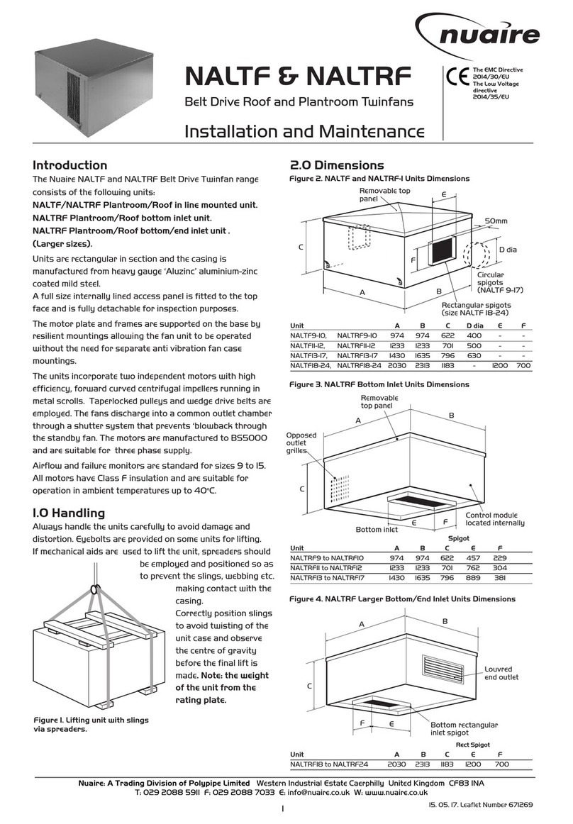
Figure 1. Typical installations show unit with top discharge.
Figure 2.
The EMC Directive
2004/108/EC
The Low Voltage
directive
2006/95/EC
FLATMASTER
Low Energy Positive Input
Ventilation Unit
Installation and Maintenance
Important notes to installers
The Nuaire Drimaster/Flatmaster range has been curing severe
condensation problems for over 20 years in some of the worst
affected properties throughout the world.
Its successful operation depends entirely upon the unit being
installed strictly in accordance with these instructions. We would,
therefore, respectfully suggest that you read through this guide in
its entirety before commencing installation and then go through
this guide step by step to ensure a satisfactory completion.
Whilst the installation of the Flatmaster unit may be achieved by a
suitable craftsman, the provision of the electrical supply and the
connection of the unit to the mains must be carried out by a qualified
electrician.
The unit has a 5 year warranty starting from the day of delivery and
includes parts and labour for the first year. The remaining 4 years
covers parts only. This warranty is conditional on the following:-
a) That the unit is installed strictly in accordance
with this guide.
b) That the unit filters are removed and cleaned or
replaced at the recommended intervals.
The unit represents a significant financial outlay on the part of the
user/specifier and the unique 5 year warranty is important to them.
We make a point of advising them that the installer is provided with
detailed instructions regarding installation/guarantee registration
and therefore has the responsibility of ensuring that the unit is
guaranteed for the user/specifier.
1.0 Installation
The unit is designed to take fresh air from outside, clean the air,
warm it (if fitted with heater) and discharge it into the central hall-
way via a system of ducting supplied by the installer. The dwelling
internal air discharge grille is usually installed at high level in a
central location within the hallway, although discharging the air
down the length of the hallway (away from the front door) should
also prove acceptable. Unit performance may be enhanced if an
existing heat source can warm the discharged air eg. by locating the
discharge grille above a radiator.
Before commencing installation decide the best position for the unit
and where the fresh air input air is to come from and be discharged to.
The unit can be installed in many different configurations and is
supplied with enough interchangeable spigots to enable it to be used
with either round (100mm) or rectangular ducting (121mm x 60mm).
The unit can be turned through 180oto any angle if required.
Fixing the unit to the wall
The unit has four mounting pads. Mark through these pads when the
unit is in the correct position. Drill and plug wall with suitable fixings.
Remove PCB cover and feed the electrical supply cable through the
grommet hole (standard 1mm three core lighting cable is recommended)
in the rear of the unit screw unit to wall.
Points to consider
1. The inlet ducting should be kept as short as possible to avoid
condensation build up on the ducting surface (see figs 5/6).
2. Can the discharge grille be located to take advantage of existing
heat sources?
3. Find the shortest, most direct route from outside of the unit and
then to the discharge grille using the least number of bends
(these bends increase the airflow resistance).
4. Note the location of any joists, pipes, electrical cables etc.
5. Allow adequate access to the front cover to allow filter cleaning?
6. Refer to the relevant Building and Electrical Regulations.
Setting up the correct airflow direction
IMPORTANT
The internal grille must not be placed within 1.5m of a smoke alarm.
Fitting the deflector plate
Fit deflector plate into scroll cover as shown below. Once fitted the
assembly can be slotted into the scroll and clipped firmly in place.
Transformation Piece
This should be on the appropriate scroll outlet. The transformation
piece should be fitted into the chosen outlet spigot insert, prior to
fitting.
Note: If the round spigot is used as an outlet, the 115 x 55mm clear
blanking plate will need to be fitted (as shown). This plate should be
prevented from movement by the use of silicone sealant.
Inlet/Outlet Grille installation
If a flyscreen is fitted it should be removed from both the internal
and external grille.
NOTE: When installing the internal grille, the louvres MUST SLANT
UPWARDS to ensure the correct air circulation and the avoidance of
unpleasant downdraughts.
The outside wall input grille louvres MUST SLANT DOWNWARDS.
Standard 100mm dia ducting or 121 x 60mm ducting is used to
connect the Flatmaster to the input and discharge grilles.
Fixing all necessary ducting
A full range of ductwork and ductwork ancillaries are available.
Please contact Nuaire for further details.
2.0 Heater Options
(order code FLAT-HEATER)
The heater kit contains a blank insert with a cut out for the switch.
This blank can be fitted into any appropriate opening. It is important
that the switch is fitted so that the terminals are at the bottom.
Heater option wiring detail for general application
(other than bathroom)
All wiring is supplied for connecting the heater to the main PCB.
The unit is supplied with cable ties and sticky pads to enable any
excess cable to be restrained. Note: If the heater is to be controlled
off a remote switch/thermostat this should be wired into the live line
between the main PCB and unit mounted switch, in accordance with
current IEE regulations.
Installation and Maintenance FLATMASTER Low Energy Positive Input Ventilation Unit
2Leaflet Number 670833 July 2009
Figure 4. Figure 7.
Figure 5. Side input installation.
Figure 6. Rear input installation (view from above).
I
I
I
I
I
I
I
I
I
I
I
I
I
I
Figure 8.
Figure 3.
Heater option wiring detail for (bathroom
application)
If units are installed in a bathroom the unit mounted heater switch
cannot be used. A remote neon indicator switch (by others)
complying and installed to the latest regulations should be used.
The power to the heater should be taken directly from the remote
switch to the heater via the terminal block, and should not use the
supply from the mains PCB.
3.0 Electrical details
Supply - 230V 1 phase 50Hz
Power Consumption
(without heater option)
Speed 1 - 5 Watts
Speed 2 - 8 Watts
Speed 3 - 13 Watts
Optional Heater - 300 Watts.
The unit should be wired in accordance with current IEE regulations.
Electrical connection
Please note the electrical connections to the unit should be carried
out by a qualified electrician.
With the PCB cover removed (see figure 2) pull the PCB forward to
gain access to earth post behind. Connect Earth cable to Earth Post
next to the grommet hole. (If the heater option is required the wiring
should be connected to the appropriate terminal on the PCB).
Slide PCB into slot and connect the mains supply L and N to the
terminal block.
4.0 Setting the Unit
The speed selector is located on the PCB (see bathroom application
figure 11) The unit has a choice of three speeds to suit the size of the
dwelling and the moisture being generated. The unit is factory set at
No 3. We recommend that the unit is operated at this speed and the
setting reduced if and when necessary in the future.
Replace PCB cover and test the unit. Check rotation of fan with
diagrams under airflow direction. If direction is incorrect, isolate the
unit, remove PCB cover and alter the rotation switch (mounted on
the PCB). Replace PCB cover and re-check direction of fan. Replace
filter and front cover.
Optional Hour Run Monitor
This simple plug in device monitors the number of hours the unit
has been in operation. It will start from the moment the monitor is
plugged in and the unit switched on (refer to figures 8 and 9).
5.0 Maintenance
The only maintenance required is the removal and cleaning of the
filter every 12 months to 2 years. (The filter can also be vacuum
cleaned).
IMPORTANT
For good EMC engineering practice, any sensor cables
or switched live cables should not be
placed within 50mm of other cables or on the same
metal cable tray as other cables.
Any air intake terminal MUST be installed in accordance with
the appropriate regulation.
As a guide, the BS5440 series of British Standards deals with
this issue and currently states that an air intake must be at a
minimum distance of 300mm from a gas boiler balanced flue.
Installers are advised to be aware of the requirements of this
standard when installing ‘through the wall’ supply air ducting.
Similarly, supply and extract air grilles should be
at least 300mm apart.
Installation and Maintenance FLATMASTER Low Energy Positive Input Ventilation Unit
3Leaflet Number 670833 July 2009
Figure 11. PCB Panel (viewed end on).
Figure 9.
3.1 Smoke alarm automatic shut down
If the unit is required to switch off in the event of smoke detection,
alarms are available with separate relay bases from companies
such as:
Dicon Safety products – www.diconsafety.co.uk
Aico Ltd – www.aico.co.uk
Figure 10. Typical wiring (refer to manufactures specific instructions)
Mains power Smoke Nc contacts
N
LFlatmaster
PCB
L N C NC NO
230V
Supply
230V
Installation and Maintenance FLATMASTER Low Energy Positive Input Ventilation Unit
Users Guide
Q. What is a Flatmaster Home Improvement Unit?
A. It is a small wall mounted, air cleaning/moving device that
continuously inputs filtered fresh air into the dwelling from
outside.
Q. What does the unit do?
A. The unit will cure and/or prevent the problems associated with
condensation in your home, providing a cleaner, healthier living
environment for all occupants. The unit will prevent mould
growth on walls, ceilings, furniture, clothes and curtains.
The unit also eradicates the musty smells evident in homes with
severe condensation problems.
Q. How does it work?
A. Simply and very efficiently. Outside air is drawn into the unit,
filtered and then ducted into a central area (typically the hallway/
stairwell) of the dwelling. However, the performance of the unit
may be enhanced if an existing heat source can be mixed with the
discharged air. For instance, the unit could be mounted to
discharge into an airing cupboard. The cupboard would then
have an outlet grille fitted in the top of its sidewall to supply
tempered air into the dwelling. As the air is supplied into the
dwelling it mixes with the warmer air that naturally accumulates
at ceiling level taking advantage of the heat from this warm air
you have paid for but are not making use of. This tempered,
fresh, clean air then continuously and gently dilutes, displaces
and replaces the air within your home. The result is a home free
from serious condensation and a more pleasant and comfortable
environment.
Q. How much does it cost to run?
A. When you consider the advantages the unit will provide for you
and the other occupants, the running costs are insignificant.
However, it should be remembered that the unit is making use of
heat at ceiling level that would otherwise be lost.
Q. How do I operate the unit?
A. You don’t have to. From the time the installer starts the unit it
will run continuously for many years of trouble free use.
Q. What maintenance is required for the unit?
A. Very little. The only maintenance required is the removal and
cleaning of the filter every 12 months to 2 years. (The filter can
also be vacuum cleaned).
Q. How will I remember to clean the filters?
A. When the filters become dirty, the unit does not input as much air
into the dwelling. Condensation and musty smells may become
evident. This will be a signal for you to check and clean or replace
the filters as necessary.
Q. How will I know if the unit is working?
A. The unit motor may be almost inaudible but you should notice a
change of atmosphere in the hallway within a day or so. ‘Within
a few weeks any mould should start to dry out and eventually
become a grey powder which can easily be cleaned. After a
month your home will be a healthier environment free from
severe condensation dampness and probably more efficient.
Q. What do I do if the unit stops working?
A. If the unit appears to have stopped operating please contact our:
Customer Services Department
on 08705 002 555
If you are a Housing Association or Local Authority tenant however,
you should contact your Local Housing Office in the first instance.
UNITS FITTED WITH HEATER
Some units are fitted with a heater to temper the incoming air.
A heater neon indicator switch (normally mounted on the side of the
unit) is provided on these models. You can choose when you wish to
use the heater.
The installation must only be examined by a qualified electrician
and must always be isolated before an inspection. Under no
circumstances must the unit be dismantled as this will invalidate
the warranty.
Useful tips
To ensure you get the maximum benefit from your Nuaire
Flatmaster Home Improvement Unit:
1. Avoid drying clothes on radiators or indoor clothes lines.
2. Avoid having tumble dryers venting into your home.
Always vent to outside.
3. Avoid using portable unflued gas heaters.
4. Avoid using paraffin heaters.
Finally, thank you for taking the time to read this short user
guide. If you are happy with your Flatmaster 5+ Home
Improvement Unit, please tell your friends and neighbours.
If you are not - Please tell us.
4
Technical or commercial considerations may, from time to time, make it necessary to alter the design, performance and
dimensions of equipment and the right is reserved to make such changes without prior notice.
Leaflet Number 670833 July 2009

Other NuAire Fan manuals

NuAire MEV-DC2 Instruction Manual

NuAire

NuAire MEV-DC2 Instruction Manual

NuAire NALMF Series Instruction Manual

NuAire

NuAire NALMF Series Instruction Manual

NuAire AVT1-R User manual

NuAire

NuAire AVT1-R User manual

NuAire XB-EFA-8L-BK User guide

NuAire

NuAire XB-EFA-8L-BK User guide

NuAire MRXBOX95B-LOFT Instruction Manual

NuAire

NuAire MRXBOX95B-LOFT Instruction Manual

NuAire MRXBOXAB-ECO3B-1Z User manual

NuAire

NuAire MRXBOXAB-ECO3B-1Z User manual

NuAire OPUSDC-SA-60 Instruction Manual

NuAire

NuAire OPUSDC-SA-60 Instruction Manual

NuAire SQF User manual

NuAire

NuAire SQF User manual

NuAire MRXBOX95ABWM2QA12338 Instruction Manual

NuAire

NuAire MRXBOX95ABWM2QA12338 Instruction Manual

NuAire Opus 100-2M Instruction Manual

NuAire

NuAire Opus 100-2M Instruction Manual

NuAire MRXBOXAB-ECO3B-AESW User manual

NuAire

NuAire MRXBOXAB-ECO3B-AESW User manual

NuAire Genie/tops 230 volt Instruction Manual

NuAire

NuAire Genie/tops 230 volt Instruction Manual

NuAire MRXBOXAB-ECO3B User manual

NuAire

NuAire MRXBOXAB-ECO3B User manual

NuAire AX User manual

NuAire

NuAire AX User manual

NuAire MRXBOXAB-ECO5-AE User manual

NuAire

NuAire MRXBOXAB-ECO5-AE User manual

NuAire DRI-ECO-LINK-HC User manual

NuAire

NuAire DRI-ECO-LINK-HC User manual

NuAire DRI-ECO-HEAT-HC Instruction Manual

NuAire

NuAire DRI-ECO-HEAT-HC Instruction Manual

NuAire DuctMaster DCB 315 Instruction Manual

NuAire

NuAire DuctMaster DCB 315 Instruction Manual

NuAire MRXBOX95B-LH1 User manual

NuAire

NuAire MRXBOX95B-LH1 User manual

NuAire AVT-R User manual

NuAire

NuAire AVT-R User manual

NuAire Opus OK Manual

NuAire

NuAire Opus OK Manual

NuAire EST19H-X User manual

NuAire

NuAire EST19H-X User manual

NuAire EST 19H-R Instruction Manual

NuAire

NuAire EST 19H-R Instruction Manual

NuAire AVT Series Instruction Manual

NuAire

NuAire AVT Series Instruction Manual

Popular Fan manuals by other brands

Brink Flair 225 Operation manual by user

Brink

Brink Flair 225 Operation manual by user

Venmar X24 HRV ECM user guide

Venmar

Venmar X24 HRV ECM user guide

BrookVent 90-0103-WDS-01 Installation, maintenance & user manual

BrookVent

BrookVent 90-0103-WDS-01 Installation, maintenance & user manual

Elicent EXT Series instruction manual

Elicent

Elicent EXT Series instruction manual

Holmes HT38 owner's guide

Holmes

Holmes HT38 owner's guide

Mistral MTF-D5070 instruction manual

Mistral

Mistral MTF-D5070 instruction manual

Kongskilde JK-30MT Operator's manual

Kongskilde

Kongskilde JK-30MT Operator's manual

NSB FAN FA701 instruction manual

NSB FAN

NSB FAN FA701 instruction manual

Create WIND PROP user manual

Create

Create WIND PROP user manual

Sealey STF30 manual

Sealey

Sealey STF30 manual

Suncourt DB100C installation instructions

Suncourt

Suncourt DB100C installation instructions

BLAUBERG Ventilatoren Moon user manual

BLAUBERG Ventilatoren

BLAUBERG Ventilatoren Moon user manual

Uberhaus FZ-18D user manual

Uberhaus

Uberhaus FZ-18D user manual

McQuay MWM-G2W Technical manual

McQuay

McQuay MWM-G2W Technical manual

VEOHAUT BL-FS7-D instruction manual

VEOHAUT

VEOHAUT BL-FS7-D instruction manual

Trisa electronics 9346.43 Instructions for use

Trisa electronics

Trisa electronics 9346.43 Instructions for use

Gorenje BVN W Series Instructions for installation and use

Gorenje

Gorenje BVN W Series Instructions for installation and use

DELTA BREEZ 80RLED-ADJ manual

DELTA BREEZ

DELTA BREEZ 80RLED-ADJ manual

manuals.online logo
manuals.online logoBrands
  • About & Mission
  • Contact us
  • Privacy Policy
  • Terms and Conditions

Copyright 2025 Manuals.Online. All Rights Reserved.