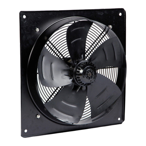
Hydor HXP EC User manual

Please take note of the following symbols used within this document:
Warning: Hazards associated with electric current and high voltages
Important: Important information
Hydor’s policy is one of continual improvement and the right to change a specication at any time
without notice is reserved. Whilst every care has been taken to ensure that the contents of this
document are correct at time of publication, Hydor shall be under no liability whatsoever in respect
of such contents.
Hydor cannot guarantee the operation of any equipment unless all documented instructions are
complied with, without variation.
Hydor is a registered trademark of EG Agri Ltd and is a member of Elta Group. All other trademarks,
trade names or company names referenced herein are the property of their respective owners.
Installation and Maintenance Instructions.
THESE INSTRUCTIONS MUST BE READ FULLY BEFORE COMMENCING INSTALLATION.
Owner / installer: The life of this apparatus and its eciency will be increased if
its use and maintenance is carried out in accordance with these instructions and
current statutory requirements. The installation and initial adjustments should
be carried out by a qualied and competent technician. Hydor Limited should be
consulted before substituting or tting parts from another manufacturer. It is the
responsibility of the installer to verify that the installation is in accordance with all
current statutory requirements and the owner is given the current User’s Manual.
Any modications to the fan or its installation, even the smallest
modication, change or elimination of security components or pieces
that inuence the eciency or loss of ventilation, will result in the CE
Certication and Hydor’s warranty being cancelled.
HXP EC
incorrect
correct, minimum height 5mm

1. General
1.1 It is important these Installation and Maintenance Instructions are fully
adhered to.
1.2 Full details of the unit supplied are shown on the product nameplate. If in
doubt about any detail contact Hydor or its agents for clarication.
1.3 All electrical installation must be carried out by suitably qualied and
competent personnel in accordance with all current statutory
requirements.
1.4 These instructions cover only the Hydor product and do not include
the supply or installation of any safety equipment that may be required
e.g. adequate guarding or protection from rotating parts and proper
electrical isolation.
1.5 Any declarations made by Hydor about product installation and safety,
are dependent on the fan equipment being used within installations which
themselves meet the requirements of the relevant Standards and
Directives of your region.
1.6 The fan is designed for use in an ambient temperature of -20°C up to a
maximum of +70°C, speed controlled operating
temperatures of -20°C and +50°C and up to 95% relative humidity. EC fans
are designed for ambient temperatures up to +60°C. The fan is not
suitable for corrosive or explosive atmospheres.
1.7 The installer should provide easy access to the fan to facilitate future
maintenance.
1.8 The installer should ensure the fan is adequately supported.
1.9 This product is not intended for use by persons (including children) with
reduced physical, sensory or mental capabilities, or lack of experience and
knowledge, unless they have been given supervision or instruction
concerning use of the product by a person responsible for their safety.
Children should be supervised to ensure that they do not play with
the product.
1.10 At end-of-life, the unit must be disposed of in an environmentally friendly
manner by suitably qualied and competent personnel in accordance with
the requirements of applicable Standards and Directives.
2. Installation
WARNING: The fan must be isolated from the power supply during
installation and maintenance. The fan must be earthed in accordance
with the local regulations.
2.1 Upon receipt, the fan equipment should be visually inspected to check for
any damage. Ensure that the impeller is free to rotate.
2.2 If there are any queries concerning the fan equipment, Hydor should be
contacted prior to the installation.
2.3 The fan must be securely mounted in the desired position to suit the

application. The fan can be mounted at any angle.
2.4 Check the details on the motor rating plate to ensure that the correct
power supply (voltage, frequency and phase) is available. An incorrect
power supply will lead to permanent damage to the fan motor.
2.5 Refer to the appropriate wiring diagram. Ensure that all earth connections
are made.
2.6 Means for electrical disconnection must be incorporated in the wiring
installation in accordance with the relevant wiring and electrical
regulations.
2.7 Precaution must be taken to locate the exhaust discharge terminal so as
to avoid the backow of gases into the room from the open ue of gas or
other fuel burning appliances.
3. Start Up
3.1 Before power is supplied to the unit, check that the wiring is correct as per
the fan connection diagram.
3.2 At initial start-up, check that impeller rotation and airow direction is
correct.
3.3 Check that the motor amperage drawn does not exceed the nameplate
rating.
3.4 Minimum interval between consecutive starts: 5 minutes.
3.5 Maximum 1 connection from power supply cycle per 5 minutes.
4. Fan Maintenance
4.1 Inspection of the fan at least once every 3 months is recommended to
ensure that the motor, fan blades, and supporting guards, are clean. Any
build-up of dust and deposits on the blades or guards should be removed
using a non-abrasive cleaner.
4.2 All fastenings including electrical should be checked for tightness. In
addition, all rotating items should be checked.
4.3 Bearings are of the ‘sealed for life’ type and will not need a detailed
inspection.
WARNING: This fan is tted with an auto-reset thermal contact which
switches the fan o in the event of a fault condition. Once the motor
cools down the fan may start unexpectedly.
Only a suitably qualied and competent person may carry out
maintenance after the electrical supply has been isolated.
5. Guarantee
Hydor will, free of charge, within a period of 3 year from the date of
dIspatch from their works, repair or at its option replace any goods
which are proved to have defects as a result of defective materials or
workmanship. The goods MUST be returned to Hydor carriage paid
for examination.

Level/Speed
Control
Voltage
(V)
10 10 (Ω)
99 (Ω)
88 (Ω)
77 (Ω)
66 (Ω)
55 (Ω)
44 (Ω)
33 (Ω)
21.5 (Ω)
1500 (Ω)
01 (Ω)
Please note: This is an estimated
adjustment guide
149-CD-POT
149-CD-POT
The 149-CD-POT is a commissiong device designed to be used with our EC range of fans.
This device will be as standard with our box fan range from May 2018.
The device will allow the for the installer to set the maximum operating speed of the fan that it is
connected to.
The installer or commissioning engineer can adjust the fan speed using the potentiometer built onto the
149-CD-POT board. This potentionmeter can either be used for single speed adjustment or to set a
maximum speed for the fan to operate at when an external control source is used.
If external speed control is required, the jumper connection next to the potentionmeter on the board
would need to be removed, the installer can then connect to ST1 (using the diagram provided).
When an external speed control is tted, the maximum speed setting available to the external control is
limited by the potentiometer setting of the commissioning device.
10/07/2018
MK-149-CD-POT Issue: Saved Date:A
The 149-CD-POT is a commissiong device designed to be used with our
EC range of fans.
The device will allow the for the installer to set the maximum operating speed
of the fan that it is connected to.
The installer or commissioning engineer can adjust the fan speed using the
potentiometer built onto the 149-CD-POT board.
This potentiometer can either be used for single speed adjustment or to set
a maximum speed for the fan to operate at when an external control source
is used.
If external speed control is required, the jumper connection next to the
potentiometer on the board would need to be removed, the installer can
then connect to ST1 (using the diagram provided).
When an external speed control is fitted, the maximum speed setting
available to the external control is limited by the potentiometer setting of
the commissioning device.
All wiring and control equipment must comply to the latest IEE regulations, in particular part 552-01-02/03.
149-CD-POT Issue A: 10.07.2018
Check the individual product accessories table for fan controller compatibility.

GND
10V
E1
MIN
MAX
E1
GND
ST1
ST2
ST2
E1
10V
GND
MAX
MIN
ST1
GND
E1
THE ABOVE DIAGRAM SHOWS "ST2".
"ST2" CONNECTIONS ARE FACTORY FITTED.
GND
= COMMON
•
10V
= 10VDC INPUT
•
E1
= 0-10VDC OUTPUT
•
YOU CAN DETERMINE THE CURRENT VDC OUTPUT BY
DISCONNECTING POWER TO THE UNIT, SETTING A
MULTIMETER TO OHMS (Ω) AND PLACING THE TEST PROBES
BETWEEN GND AND E1
PLEASE USE THE ESTIMATED ADJUSTMENT GUIDE FOR REFERENCE
THIS IS THE INTERNAL POTENTIOMETER
THIS POTENTIOMETER CAN BE ADJUSTED FOR SINGLE SPEED
SETTING OR MAX SPEED SELECTION
THIS LINK/JUMPER SHOULD BE REMOVED
WHEN USING AN EXTERNAL POTENTIOMETER
OR EXTERNAL CONTROL SIGNAL CONNECTED
TO "ST1"
THE ABOVE DIAGRAM SHOWS "ST1".
"ST1" CONNECTIONS ARE CLASSED AS
"CUSTOMER/USER CONNECTIONS".
GND
= COMMON
•
+
= VDC OUTPUT AS SET BY
•
INTERNAL POTENTIOMETER
E1
= 0-10VDC INPUT
•
149-CD-POT
10/07/2018
MK-149-CD-POT
Issue:
Saved Date:
A
All wiring and control equipment must comply to the latest IEE regulations, in particular part 552-01-02/03.
149-CD-POT Issue A: 10.07.2018
Check the individual product accessories table for fan controller compatibility.
GND
10V
E1
MIN
MAX
E1
GND
ST1
ST2
ST2
E1
10V
GND
MAX
MIN
ST1
GND
E1
THE ABOVE DIAGRAM SHOWS "ST2".
"ST2" CONNECTIONS ARE FACTORY FITTED.
GND
= COMMON
•
10V
= 10VDC INPUT
•
E1
= 0-10VDC OUTPUT
•
YOU CAN DETERMINE THE CURRENT VDC OUTPUT BY
DISCONNECTING POWER TO THE UNIT, SETTING A
MULTIMETER TO OHMS (Ω) AND PLACING THE TEST PROBES
BETWEEN GND AND E1
PLEASE USE THE ESTIMATED ADJUSTMENT GUIDE FOR REFERENCE
THIS IS THE INTERNAL POTENTIOMETER
THIS POTENTIOMETER CAN BE ADJUSTED FOR SINGLE SPEED
SETTING OR MAX SPEED SELECTION
THIS LINK/JUMPER SHOULD BE REMOVED
WHEN USING AN EXTERNAL POTENTIOMETER
OR EXTERNAL CONTROL SIGNAL CONNECTED
TO "ST1"
THE ABOVE DIAGRAM SHOWS "ST1".
"ST1" CONNECTIONS ARE CLASSED AS
"CUSTOMER/USER CONNECTIONS".
GND
= COMMON
•
+
= VDC OUTPUT AS SET BY
•
INTERNAL POTENTIOMETER
E1
= 0-10VDC INPUT
•
149-CD-POT
10/07/2018
MK-149-CD-POT
Issue:
Saved Date:
A
GND
10V
E1
MIN
MAX
E1
GND
ST1
ST2
ST2
E1
10V
GND
MAX
MIN
ST1
GND
E1
THE ABOVE DIAGRAM SHOWS "ST2".
"ST2" CONNECTIONS ARE FACTORY FITTED.
GND
= COMMON
•
10V
= 10VDC INPUT
•
E1
= 0-10VDC OUTPUT
•
YOU CAN DETERMINE THE CURRENT VDC OUTPUT BY
DISCONNECTING POWER TO THE UNIT, SETTING A
MULTIMETER TO OHMS (Ω) AND PLACING THE TEST PROBES
BETWEEN GND AND E1
PLEASE USE THE ESTIMATED ADJUSTMENT GUIDE FOR REFERENCE
THIS IS THE INTERNAL POTENTIOMETER
THIS POTENTIOMETER CAN BE ADJUSTED FOR SINGLE SPEED
SETTING OR MAX SPEED SELECTION
THIS LINK/JUMPER SHOULD BE REMOVED
WHEN USING AN EXTERNAL POTENTIOMETER
OR EXTERNAL CONTROL SIGNAL CONNECTED
TO "ST1"
THE ABOVE DIAGRAM SHOWS "ST1".
"ST1" CONNECTIONS ARE CLASSED AS
"CUSTOMER/USER CONNECTIONS".
GND
= COMMON
•
+
= VDC OUTPUT AS SET BY
•
INTERNAL POTENTIOMETER
E1
= 0-10VDC INPUT
•
149-CD-POT
10/07/2018
MK-149-CD-POT
Issue:
Saved Date:
A

NOTE: TAG REFERENCES RELATE TO MOTOR CONTROL WIRES, AND NOT 149-POT-10
0-10V DC INPUT (IF REQUIRED)
GND 0-10 VDC
6
5
BLACK
BROWN
REMOVE LINK WHEN USING
EXTERNAL POTENTIOMETER OR
EXTERNAL CONTROL SIGNAL
POTENTIOMETER FOR SINGLE
SPEED ADJUSTMENT OR MAX
SPEED SELECTION
PENL
POWER CONTROLS
RED
BLUE
WHITE
YELLOW
G/Y
BLUE
BROWN
220 - 277V 1PH 50Hz
MAINS SUPPLY
LN
SINGLE FAN
1PH EC SINGLE FAN C/W 149-CD-POT & 0-10VDC INPUT
BLUE
BROWN
GREEN/YELLOW
GND 10V E1
MIN MAX
E1GND
ST1
ST2
149-CD-POT
234
1
FOR USE WITH:
SCP250-1EC
SCP315-1EC
SCP350-1EC
SCP400-1EC
SCP450-1EC
SCP500-1EC
SCP560-1EC
SCP630-1EC
SCP710-1EC
NOTE:
*JUMPER REMOVED WHEN EXTERNAL
CONTROL SOURCE IS USED.
1 5672
149-POT-10
14
3
2
149-CD-POT
ST2
ST1
GND E1
MAX
MIN
E110VGND
GREEN/YELLOW
BROWN
BLUE
1PH EC SINGLE FAN C/W 149-CD-POT & 149-POT-10
SINGLE FAN
N
L
220 - 277V 1PH 50Hz
MAINS SUPPLY
BROWN
BLUE
G/Y
YELLOW
WHITE
BLUE
RED
CONTROLS
POWER
L N PE
MAX SPEED
TRIMMER
JUMPER
REMOVED *
BROWN
BLACK
56
FOR USE WITH:
SCP250-1EC
SCP315-1EC
SCP350-1EC
SCP400-1EC
SCP450-1EC
SCP500-1EC
SCP560-1EC
SCP630-1EC
SCP710-1EC
14
3
2
149-CD-POT
ST2
ST1
GND E1
MAX
MIN
E110VGND
GREEN/YELLOW
BROWN
BLUE
1PH EC SINGLE FAN C/W ONE WAY SWITCH
SINGLE FAN
N
L
220 - 277V 1PH 50Hz
MAINS SUPPLY
BROWN
BLUE
G/Y
YELLOW
WHITE
BLUE
RED
CONTROLS
POWER
L N PE
MAX SPEED
TRIMMER
JUMPER
REMOVED*
BROWN
BLACK
56
FOR USE WITH:
SCP250-1EC
SCP315-1EC
SCP350-1EC
SCP400-1EC
SCP450-1EC
SCP500-1EC
SCP560-1EC
SCP630-1EC
SCP710-1EC ONE WAY SWITCH
NOTE:
*JUMPER REMOVED WHEN EXTERNAL
CONTROL SOURCE IS USED.
-
Tag Purpose Description
L Live Live power supply, 220-277V
N Neutral Neutral from power supply
Permanent Earth Permanent earth from power supply
1DC Voltage [2-10V] DC control voltage input
(2 to 10VDC input)
2 DC Current [4-20mA] DC control current input
(4 to 20mA input)
3 Frequency [10-95%]
Frequency duty-cycle (PWM)
Voltage: 10 to 24Vpk
Frequency: 80Hz
(10 to 95% input)
4 Speed Reference Tacho output
5 10VDC output 10VDC source output
6 GND / Common DC Common
ALL WIRING AND CONTROLS EQUIPMENT MUST COMPLY TO THE
LATEST IET REGULATIONS, IN PARTICULAR PART 552-01-02/03
10/09/2019
MK-152-711 Issue: Saved Date:D
All wiring and control equipment must comply to the latest IEE regulations, in particular part 552-01-02/03.
MK-152-711 Issue C: 15.01.2019
Check the individual product accessories table for fan controller compatibility.

Guarantee
Hydor or its agents will, within a period of one year from the date of dispatch
from their works, at its option, repair or replace any goods, which are proven to
have defects as a result of defective materials or workmanship. The goods must
be inspected by a Hydor ocial and if necessary returned, with a Returns Note
Number, carriage paid, for further examination.
EG Agri Ltd
Hydor
Unit 8, Parkers Close, Downton Business Centre,
Downton, Salisbury, Wiltshire, SP5 3RB, UK
Tel: +44 (0) 1725 511422
Email: info@hydor.co.uk
Web: www.hydor.co.uk
idealair group
Unit 1, Building 1, Sydney Corporate Park,
85 O’Riordan Street, Alexandria NSW 2015
Tel: +61 (02) 8073 3310
Fax: +61 (02) 8073 3320
Email: info@idealairgroup.com.au
AMS
11 Ingrid Road, Montague Gardens,
7442 Cape Town, Western Cape
Tel: +27 (0) 21 552 1077
Fax: +27 (0) 21 552 2797
Inst Issue 2: 08.21
Table of contents
Other Hydor Fan manuals

Hydor
Hydor HVWC800 User manual

Hydor
Hydor HV800 User manual

Hydor
Hydor HXP45041 User manual

Hydor
Hydor HIMF100 User manual

Hydor
Hydor HV Series User manual

Hydor
Hydor HEB Technical specifications

Hydor
Hydor HPA250/2-1A Technical specifications

Hydor
Hydor HXSU450 User manual

Hydor
Hydor HV800 User manual

Hydor
Hydor HDSF500/6/1/230 User manual