MAGNUM
Page 9
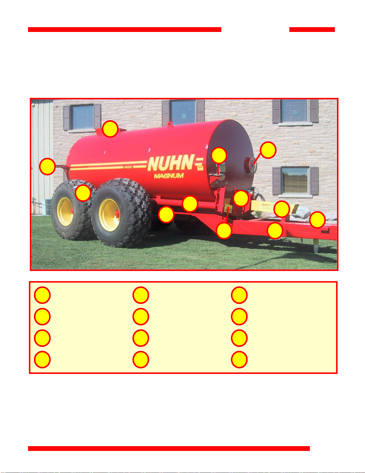
Tire Pressure and Maintenance
Follow the manufacturer’s recommendations for your particular tire.
Wheel Bolt Torque
Tighten the 3/4” bolts on the 10-bolt rim to 300 foot-pounds.
Tighten the 5/8” bolts on the 8-bolt rim to 100 foot-pounds.
If you don’t have a torque wrench:
300 foot-pounds = 100 lbs of pressure on a 3 ft. handle
100 foot-pounds = 35 lbs of pressure on a 3 ft. handle
Axle
The four grease fittings on the axle should be greased before initial use of the spreader and then
the seasonally.
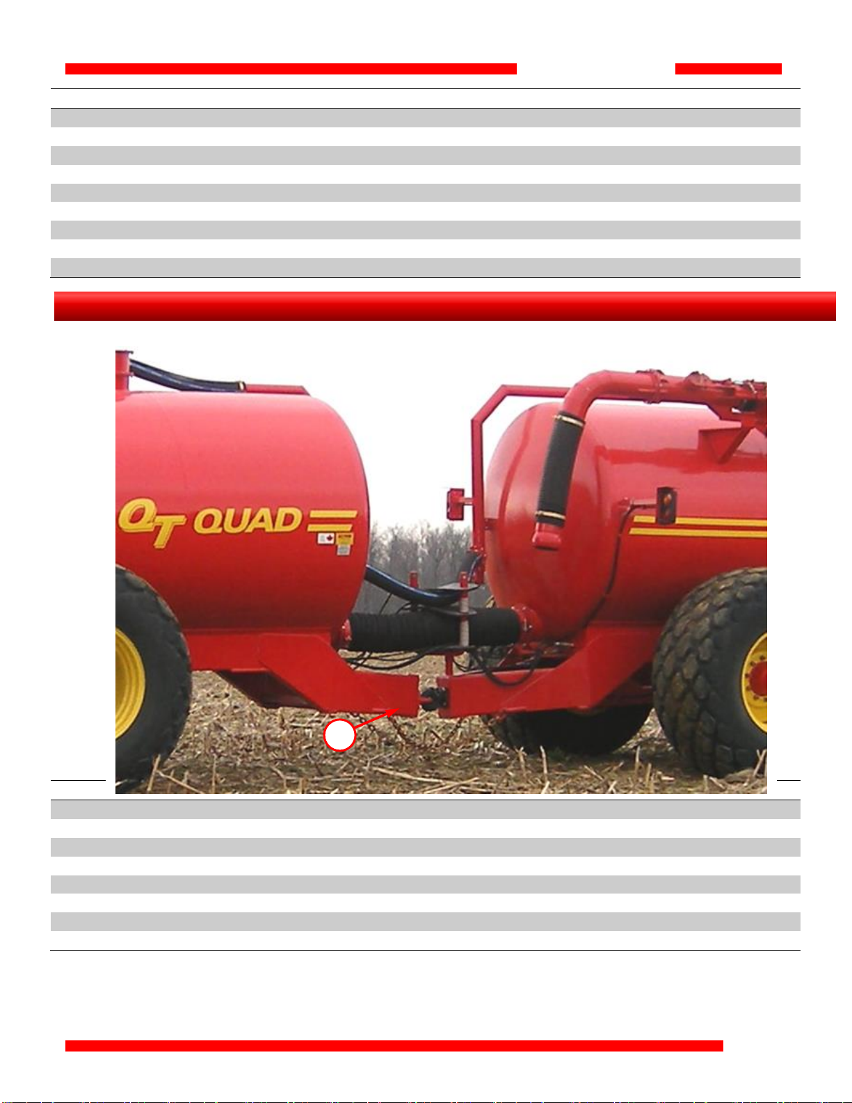
Storage Tips
1. At the end of the season, rinse out the spreader. Put at least 18” of water in the tank,
agitate, and then spread out the water.
2. Remove the clean-out doors to dry the tank’s interior.
3. Open the drain latch at the bottom of the front pump to prevent freezing.
4. The front pump lever should be left in the spread position to drain the side.
5. Secure the jack and block the tires.
6. Wheel hubs should have approximately ten shots of grease.
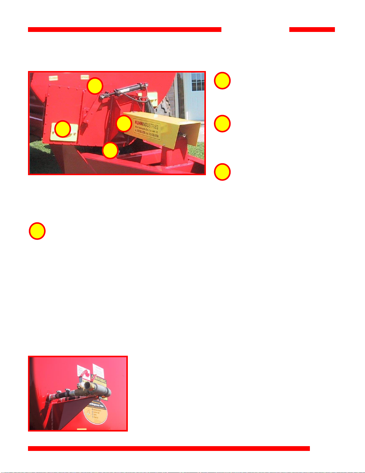
Safety
Brakes are available as an option on the manure spreader and are recommended on the 5000
model and larger.
2. Transportation problems when towing a full load.
Caution should be used when handling, controlling, and braking with the extra weight of a full
spreader behind the tractor. Speed should also be reduced.
Wheel nuts should be checked for tightness frequently the first few loads and then
periodically. The main spindle nut should be tightened and then loosened by a quarter
turn. Over tightening will result in bearing failure.