NuTone CV653 User manual

BUILT-IN CENTRAL
CLEANING SYSTEM
INSTALLATION INSTRUCTIONS FOR:
MODELS: CV653 & CV750
GENERAL INFORMATION..............2
PLANNING AND LAYOUT .............2
Examples ........................................2
Locating the Power Unit..................3
Locating the Wall Inlets...................3
Tubing.............................................3
INSTALLATION IN
NEW CONSTRUCTION....................4
Wall Inlet Rough-In .........................4
Installing the Tubing........................4
Tubing Installation...........................5
Wall Inlet Installation.......................6
Model 360 Wall Inlet ...................6
Model 330 Wall Inlet ...................6
Power Unit Installation ....................7
Dimensional Chart ........................7
Mounting .......................................7
Tubing connections.......................7
Wiring............................................7
INSTALLATION IN
EXISTING CONSTRUCTION ...........8
Planning and Layout .......................8
Locating Access Keys.....................8
Wall Inlet Installation.......................8
Model 330 Wall Inlet .....................10
FLOOR INLET INSTALLATION.....10
FINAL SYSTEM CHECK................11
Model CV750 Shown

2
GENERAL INFORMATION
PLANNING AND LAYOUT EXAMPLES
The NuTone Central Cleaning System consists of a Power Unit,
PVC Tubing, PVC Fittings, Wall Inlets, a flexible hose and
various cleaning attachments.
As an aid in planning the installation in either new or existing
construction, look at the following examples:
Here the power unit is mounted in the
garage. The intake and exhaust tubing,
the only exposed
tubing in the
installation, runs
up the garage wall
and into the attic.
The trunk line runs
horizontally through
the attic from the
power unit to the
farthest inlet location.
Branch lines spread
throughout the attic,
connecting the trunk line
to the inlet tubing. Each inlet tube is threaded
vertically through an inside wall. Located in hallways,
and in large rooms, the inlets are placed to provide maximum
access to all cleaning areas. See Figure 1.
In this installation, the power unit is mounted in the basement,
conveniently located for shop use and messy cleaning jobs. The
intake tubing runs up the basement wall and connects to the
main trunk line, which runs along the unfinished basement
ceiling. Two first-floor inlets are connected to the trunk line by
vertical inlet lines run through interior walls. In the center of the
house, a vertical branch line runs from the basement trunk line,
through stacked closets, up into the attic. A second trunk line
runs across the attic and two branch lines connect to inlet
lines which are dropped down through upstairs interior
walls. See Figure 2.
The double-trunk line system is commonly used in
two-story houses. Finding the “key” to an accessible
vertical area is the most important step in this kind
of installation.
The Power Unit is designed to be wall-mounted away from the
living area of the home and connected to the living area by
means of permanently installed in-wall tubing and fittings.
EXHAUST
TRUNK LINE
BRANCH LINE
INLETS
POWER
UNIT INTAKE
INLET LINE
VERTICAL
BRANCH
LINE
ATTIC
TRUNK
LINE
INLET
LINE
INLET
EXHAUST
INTAKE
POWER
UNIT
BASEMENT
TRUNK LINE
FIGURE 2
FIGURE 1
THE RANCH STYLE HOUSE
THE TWO-STORY HOUSE

3
FIGURE 3
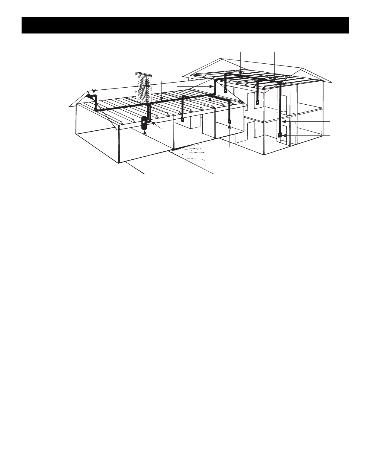
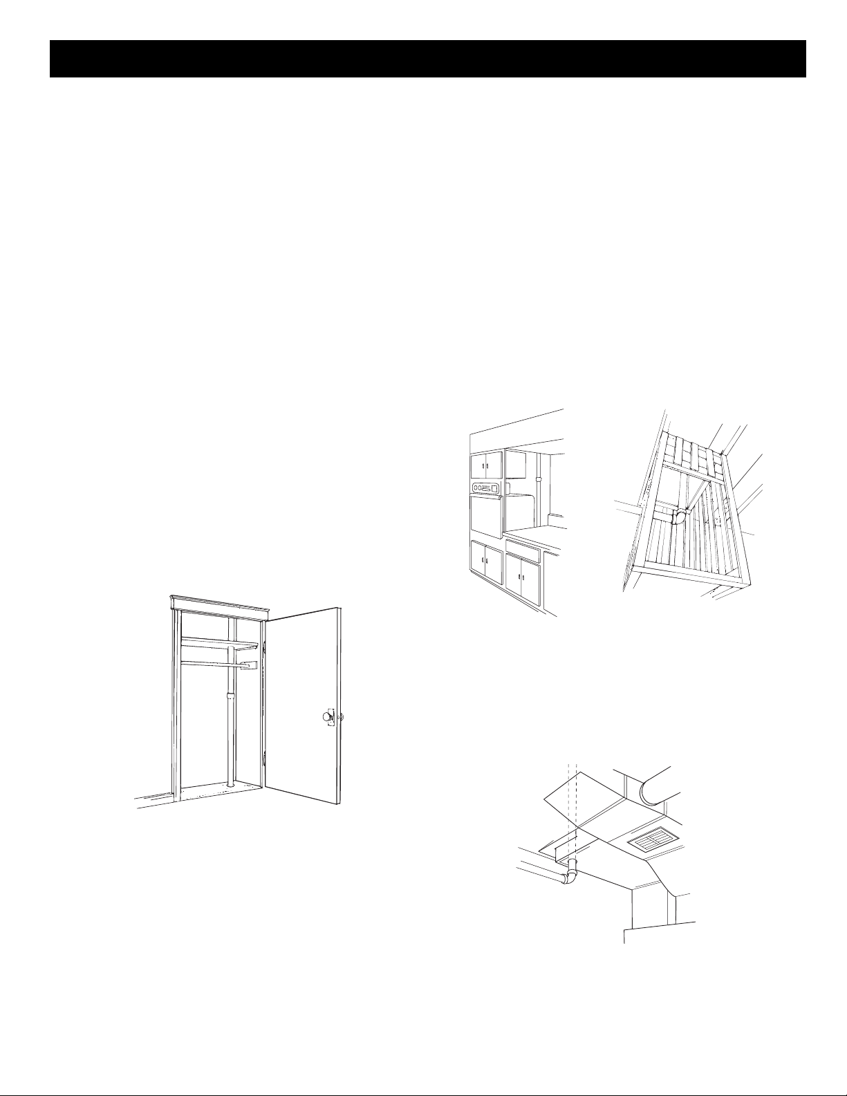
Like the two-story house, the split level installation
commonly calls for a two-level trunk line. Here, the
power unit is located in the garage. The
intake tubing runs
exposed up the
garage wall and
into the ground
level section's
attic. Two branch
lines connect this
part of the trunk
line to inlet lines
which are dropped
inside interior walls. A
vertical branch line runs
to the upstairs attic, where
the trunk line branches into
a T-shape. This trunk line connects
to two upstairs inlet lines and to one inlet
line which drops through an upstairs wall and
down into the third-level utility room to service this
entire level. See Figure 3.
EXHAUST
POWER
UNIT
INTAKE
TRUNK
LINE
VERTICAL
BRANCH
LINE
BRANCH
LINES
INLET
LINE
INLET
INLET
BRANCH
LINE
• Locate the power unit away from the general living area.
• When planning, remember the power unit is equipped with
an inlet to service a garage, basement, utility room, etc.,
wherever it is located.
• Locate the power unit in an accessible area for changing the
soil bag and periodically cleaning the secondary filter.
• Locate the power unit within six feet of a grounded electrical
outlet. The power unit requires a 120v AC power source.
• Do not locate the power unit close to a source of extreme heat
(i.e., water heater) or in an area with a high ambient
temperature (i.e., attic, furnace room).
• If the power unit is located in a closet or a small utility room,
make sure the area is well-ventilated (i.e., with door louvers).
• The power unit should be exhausted to the outside. The
exhaust should not be vented into a wall, a ceiling or a
concealed space in the house. The exhaust line should be
terminated outside the home, using Model 393 Wall Cap or a
roof vent.
WARNING: Power unit must not be mounted in a high
ambient temperature area such as attic, furnace room, etc.
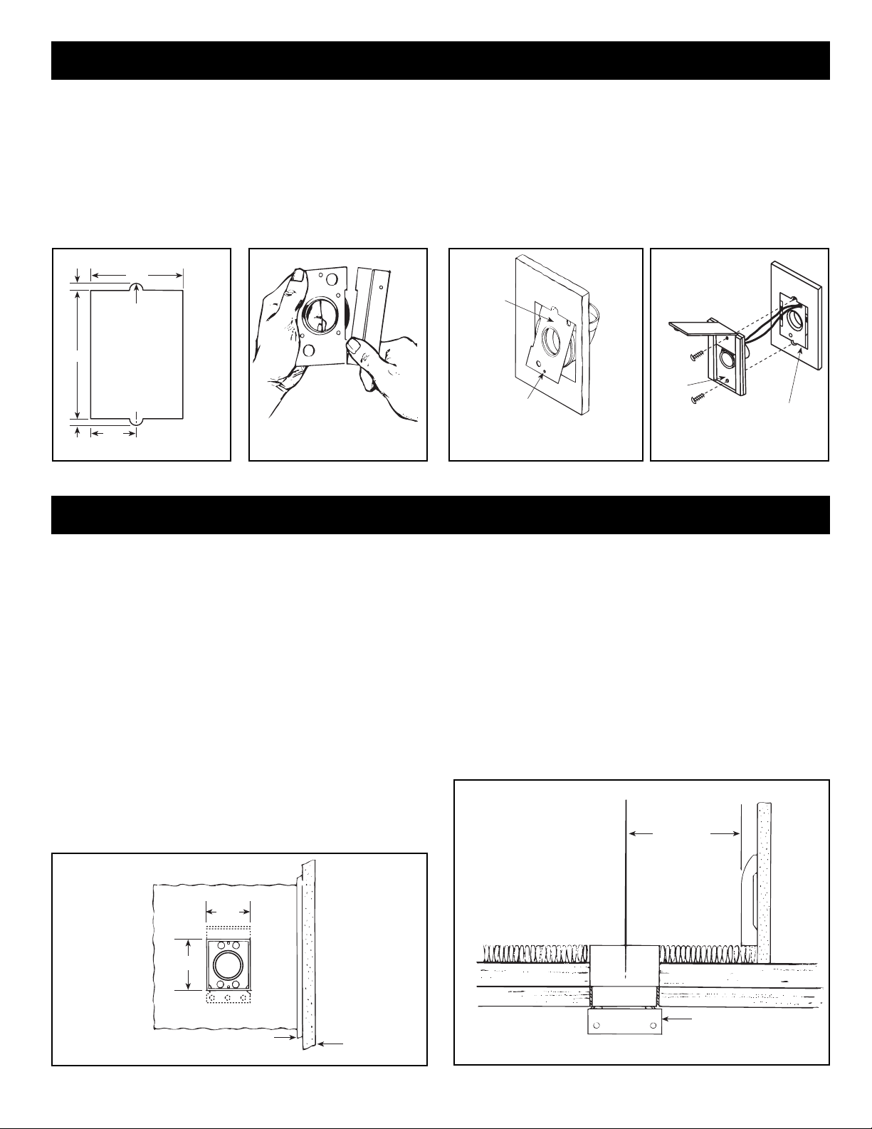
LOCATING THE WALL INLETS
• Locate inlets on interior walls.
• Choose central locations which allow several rooms to be
cleaned from a single inlet.
• Locate inlets centrally so that a maximum area can be cleaned
with the 30 foot hose.
• Locate inlet within six feet of an electrical outlet to allow use of
optional current-carrying hose.
• Be sure tubing will not obstruct electrical, plumbing or other
mechanical installation.
• Be sure inlets will not be blocked by doors or furniture.
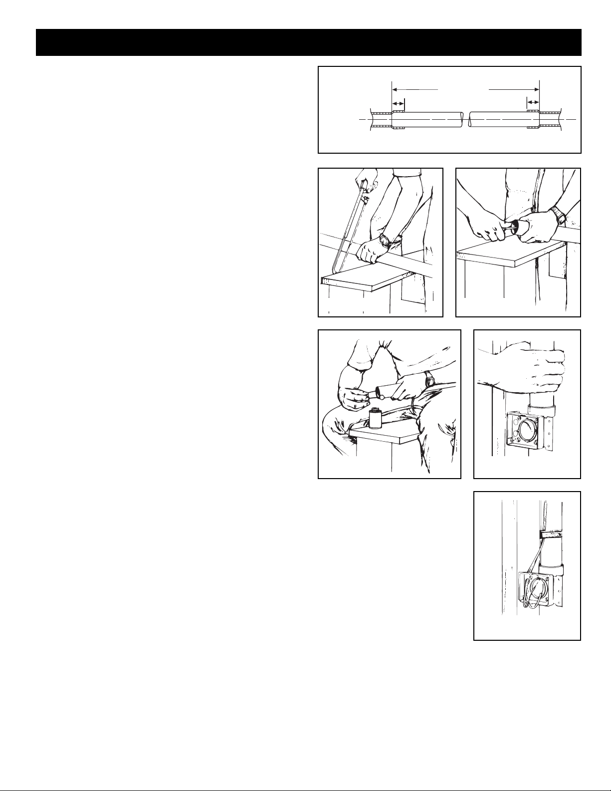
TUBING
• The installation should consist of a main trunk line running from
the farthest wall inlet to the power unit location, with branch
lines running to each additional inlet. Beginning at the area
farthest from the power unit, choose a tentative inlet location.
Measure 30 feet (for the 30-foot hose) from the proposed inlet
location to the farthest corner of the rooms to be cleaned by
that inlet to determine if inlet location is proper.
• Move tentative inlet location if necessary. Use the same
procedure to determine each additional inlet location, always
working toward the power unit.
• Generally, an installation will require 3 to 4 inlets and 16 to 20
feet of tubing per inlet. It is suggested that a floor plan be used
to more accurately determine the quantity of materials needed.
NOTE: Conventional metal or plastic strapping should
support the exhaust tubing when a muffler is used, or at
the joints of long runs of tubing where another means of
support is not available. Model CF-380 Pipe Support is
available for this purpose.
LOCATING THE POWER UNIT
THE SPLIT-LEVEL HOUSE

4
INSTALLATION IN NEW CONSTRUCTION
1. Once the locations for wall inlets have been determined,
mount all inlet brackets.
2. To locate bracket on wall stud, measure approximately 18" up
from finished floor level. (Height may vary according to
individual preference.)
MODEL 361 (FOR USE WITH 360 INLETS)
3. Refer to Figure 4. Nail bracket to side of stud so that front
edge of bracket is flush to front of stud. (The bracket may also
be nailed to the front edge of the stud. For front stud
mounting, use locating tabs on bracket for proper alignment.)
4. Refer to Figure 5. Remove cardboard from plaster guard
frame. Using four (4) provided screws, attach the appropriate
flanged fitting and inlet seal to back of inlet.
5. Replace cardboard in plaster guard frame.
MODEL 329 (FOR USE WITH 330 INLETS)
When using Model 329, glue elbow to mounting plate. Attach to
stud as shown in Figure 4A.
MODEL 329 SIDE
MOUNTING FACE
MOUNTING
MODEL 361
23/8"113/16"
FIGURE 4
21/4"31/4"
1/4"
INLET MOUNTING
BRACKET
SPACER WALL LESS THAN
1/2" THICK.
PLASTER
GUARD
HOLE
FIGURE 5
Use the following installation guidelines when installing tubing.
1. Start tubing installation at farthest inlet and work toward the
power unit.
2. Tubing run to the power unit should be as straight as
possible.
3. When assembling sections with elbows and tees, make sure
the curve in the fitting is aligned so that the air flows toward
the power unit.
4. Branch lines should always join the trunk line from above or
from the same level. Never join a branch line from an angle
below the trunk line.
5. Secure tubing to joists or studs.
6. Refer to Figure 20 on page 7. Run low voltage wiring and
secure wiring to tubing. Leave approximately 6" of wire for
connection to each inlet.
INSTALLING THE TUBING
SIDE
MOUNTING FACE
MOUNTING
MODEL 361 MOUNTING
21/2" DIA. HOLE
THROUGH SOLE PLATE
23/8"113/16"
MODEL 329 MOUNTING
2"
FACE
MOUNTING
113/16"
113/16"
21/2" DIA. HOLE
THROUGH SOLE PLATE
113/16"
FIGURE 5A
FIGURE 6
NOTE: When using the Model 361 inlet bracket on walls
thinner than 1⁄2", use a 1⁄4" spacer (not furnished) between
the wall and the inlet bracket. See Figure 5A.
Spacer may be made from plywood, Masonite™, etc. Contact
cement may be used to hold spacer in place during assembly.
Configuration of spacer may vary depending upon installation.
2" - 382S
25⁄8" - 382
FIGURE 4A
WALL INLET ROUGH-IN

5
FIGURE 7
INCLUDE FITTING
RECESS IN
MEASUREMENT
TUBING MEASUREMENT
PVC TUBING
FITTING FITTING
3/4"
3/4"
FIGURE 8 FIGURE 9
FIGURE 10 FIGURE 11
FIGURE 12
1. Cut a 21⁄2" diameter hole in sole plate, header or stud directly
in line with opening of inlet bracket fitting. Note Figures 6
and 4 for center line dimensions.
2. Refer to Figure 7. Measure length of tubing needed to
connect inlet to trunk line. Allow approximately 3⁄4" of tubing
for inserting into fittings.
3. Refer to Figure 8. Cut tubing, keeping cut square.
4. Refer to Figure 9. Remove burrs from both inside and outside
of tubing.
5. Before cementing, pre-assemble section to inlet fitting, check
for proper length.
6. Refer to Figure 10. Apply cement (Model 379) to outside of
tubing. Coat tubing approximately 1" back. Take care to keep
cement from inside of tube.
7. Refer to Figure 11. Insert tubing into fitting with a twisting
motion to evenly spread cement. Be sure tubing is firmly
seated in fitting.
8. If fittings have been attached to tubing at the end opposite the
inlet bracket, be sure alignment is proper before cement sets.
9. Refer to Figure 12. Low voltage wiring (Model 376-UL) should
be completed as tubing is installed. Tape wire to tubing to
hold in place and insert through hole in inlet bracket.
Caution: When tubing is run through the wall stud, sole
plate, headers - or anywhere that building materials will be
attached - place a nail plate (Model 378) over that area
(on both sides if necessary) to prevent nails from piercing
tubing.
TUBING INSTALLATION

6
FIGURE 15
FIGURE 16
MODEL 365
DOUBLE FLANGED
TEE WALL
INLET
MOUNTING
BRACKET
SHORTEN
WALL
FIGURE 13 FIGURE 14
MODEL 360 WALL INLET (361 Rough-in)
1. Once the walls have been finished, install the wall inlets.
2. Remove the cardboard plaster guard.
3. Refer to Figure 13. For some drywall or panel construction,
the plaster frame will extend beyond the finished wall. In this
case, remove plaster frame from mounting bracket by
removing mounting screws.
4. Refer to Figure 14. Connect 2-conductor low voltage wire to
terminal screws on back of wall inlet.
5. Guide excess wire back through hole in inlet bracket and
make sure seal is secure between mounting bracket and
flanged fitting.
6. Refer to Figure 15. Place inlet into mounting bracket and
secure.
NOTE: When wall inlets are installed in 1⁄2" thick walls or
less, the tube of the wall inlet may extend into elbow area of
the flanged fitting and cause blockage. Shorten the wall
inlet tube to prevent this condition. See Figure 16.
For extra thick walls, use Model 399 extension sleeves to
connect inlet to the flanged fitting.
MODEL 330 WALL INLET (329 Rough-in)
See Figure 17.
1. Connect 2-conductor low voltage wire to terminal screws on
back of wall inlet.
2. Align inlet mounting holes with holes in mounting plate.
3. Place inlet into mounting plate and secure with two provided
screws.
MOUNTING
PLATE
INLET
FIGURE 17
WALL INLET INSTALLATION

7
1. Using rubber couplings and hose clamps, connect intake and
exhaust tubing to the power unit.
2. Connect intake tubing to lower intake tube on power unit.
3. Connect muffler and exhaust tubing to upper exhaust tube on
the power unit.
4. Make sure all tubing connections are air tight.
5. The exhaust should not be vented into a wall, a ceiling or a
concealed space in the house. The exhaust line should be
terminated outside the home, using Model 393 Wall Cap or a
roof vent.
DIMENSIONAL CHART
MODELS
DIMENSION CV653 CV750
A32
1
⁄
4
"36
1
⁄
4
"
B7
3
⁄
4
"10
1
⁄
2
"
C6
7
⁄
8
" 12"
D13
5
⁄
8
"15
3
⁄
4
"
E6
1
⁄
8
"6
1
⁄
2
"
FIGURE 18
LOWER
SLOT
111/2"
MOUNTING
BRACKET
TOP KEYHOLE SLOT
"E"
INTAKE
FIGURE 19 FIGURE 20
POWER UNIT INSTALLATION
TUBING CONNECTIONS
MOUNTING See Figure 18.
1. Locate power unit within six feet of a grounded electrical outlet.
2. Drill 3⁄16" diameter pilot holes for the two (2) mounting screws in a
wall stud or strong support. See Figure 19.
3. Tighten mounting screws. Leave approximately 1⁄8" to 3⁄16"
clearance between head of screw and wall.
4. Hang power unit onto mounting screws. Make sure top keyhole
slot and lower slot in mounting bracket are engaged behind
mounting screws. Pull down to secure.
5. Remove dirt canister from power unit.
6. Install soil bag and securely replace dirt canister.
WIRING See Figure 20.
Grounding Instructions – This appliance must be grounded. If
it should malfunction or breakdown, grounding provides a path of
least resistance for electric current, to reduce the risk of electric
shock. This appliance is equipped with a cord having an
equipment-grounding conductor and grounding plug. The plug must
be plugged into an appropriate outlet that is properly installed and
grounded in accordance with all local codes and ordinances.
Danger – Improper connection of the equipment-grounding
conductor can result in a risk of electric shock. Check with a
qualified electrician or service person if you are in doubt as to
whether the outlet is properly grounded. Do not modify the plug
provided with the appliance – if it will not fit the outlet, have a proper
outlet installed by a qualified electrician.
This appliance is for use on a nominal 120-volt circuit and has a
grounding plug. Make sure that the appliance is connected to an
outlet having the same configuration as the plug. No adapter
should be used with this appliance.
1. Connect low voltage wire (18 gauge, 2-conductor, Model 376-UL)
to crimp connectors located on outside of the power unit.
2. The power unit is equipped with a six foot grounded cord.
Plug cord into 120 volt grounded receptacle.
MINIMUM WALL CLEARANCE DIMENSIONS
EXHAUST
INTAKE
TOP VIEW
“D”
12" 18"
12" MINIMUM TO CEILING
FRONT VIEW
INTAKE
EXHAUST
18" MINIMUM ABOVE FLOOR
“A”
OVERALL
HEIGHT
“B”
TOP OF
UNIT TO
TOP
KEYHOLE
SLOT “C”
NOTE: INLET LEADS TO BE
CONNECTED TO POWER UNIT
TERMINALS USING THE 1/4"
PUSH-ON CONNECTORS ON
POWER UNIT.
WIRING
POWER
CORD
PUSH-ON
CONNECTORS
INLET
LEADS
INLET INLET INLET
TO
OTHER
INLETS
MODEL 376-UL (18/2) WIRE
120VAC ELECTRICAL
OUTLET POWER
UNIT

8
INSTALLATION IN EXISTING CONSTRUCTION
The general planning and layout and the component locations
are the same for existing construction as for new construction.
See pages 2 and 3. Built-In Appliances. In a home where the kitchen features
built-in appliances, you'll often find a hollow space behind these
appliances. If this space lines up with an obstruction-free interior
wall above or a closet, this might be a “key” to your installation.
In a ranch-style home, this “key” would provide access to run
tubing from a basement located power unit to an attic trunk line.
You may also want to consider running exposed tubing through
cabinets or cupboards. See Figure 22A.
Laundry Chute. Pictured here is tubing run from the basement
to the attic through a laundry chute. A dumb-waiter would serve
the same purpose. See Figure 22B.
Cold-Air Return. A cold-air return often provides a straight run
from basement to other levels of the house. The ductwork is
easily cut for access. Seal around the tube when completing the
installation. See Figure 23.
FIGURE 21
FIGURE 22
FIGURE 23
AB
PLANNING AND LAYOUT
LOCATING ACCESS KEYS
Unless your home is a ranch-style house where a single trunk
line can run directly through the attic or basement, you should
first investigate your house to find the ‘key’ to running your tubing
from level to level. What you're looking for is an accessible area
that is free from obstructions and will accommodate the 2" tubing.
Let's say, for example, you have a two-story house and you
want to locate the power unit in the basement. The first floor
inlets can easily be connected to a trunk line which runs along
the basement ceiling. However, you can't find interior walls on
both the first and second floors which line up and are free from
obstacles. How do you get from the basement to the attic?
Some of the ‘keys’ you might find in your home are illustrated
here.
Stacked Closets. Many homes will have an upstairs closet
located directly above a downstairs closet. It is easy to run the
tubing from one floor level to another inside these stacked
closets. In these installations the tubing is often left exposed
inside the closets. See Figure 21.

9
Use the following procedures for installation in existing construction.
1. See Figure 24. A small ‘pilot’ or ‘locating’ hole can be drilled behind
baseboard toe strip to determine proper location of 21⁄2" diameter tubing
hole in sole plate.
2. Measure the total thickness of the wall, including baseboard. One half of
this wall thickness measured from the pilot hole (dimension ‘X’) will
determine the proper location of the 21⁄2" tubing hole in the sole plate.
3. Once desired inlet locations have been determined, cut a 21⁄2" hole in
soleplate directly in line with proposed inlet location. Check through
tubing hole to be sure no obstruction exists.
4.Be sure tubing hole is centered in sole plate and directly in line with
proposed wall inlet cutout.
BASEBOARD
TOE STRIP
PILOT HOLE
“X”
SOLE PLATE
FIGURE 24
NOTE: If 330 Wall Inlet is being used refer to Model 330 Wall Inlet
Installation on next page.
5. If area is clear, cut an inlet opening in the wall approximately 18" above the floor.
Make sure wall opening and 21⁄2" tube hole line up (Figure 25).
6. Cut a length of tubing that will extend from inlet opening to a point below floor level
(or above ceiling level in attic installation). Tape low voltage wire to tube and insert tube
through predrilled hole to a level opposite the wall opening.
7. Apply cement to tube and install flanged wall fitting. Make sure fitting is well seated
and sealed (Figure 26).
8. Remove plaster frame from mounting bracket. Pull low voltage wire through hole in
bracket and insert bracket into cutout. Secure bracket to flanged fitting with four screws
provided. Be sure seal is secure between flange fitting and mounting bracket (Figure 27).
9. Starting from farthest wall inlet location, install each inlet as described above. Working
back toward power unit, connect each branch line into main trunk line. Complete low
voltage wiring as main trunk line is continued back to power unit.
10. Attach the low voltage wires to terminal screws on back of wall inlet (Figure 28).
11. Insert wall inlet into bracket and secure with the two screws provided (Figure 29).
12. Mount power unit and complete wiring. See page 7.
21/2"
29/16"
31/16"
18"
FIGURE 25
FIGURE 27
FIGURE 28 FIGURE 29
LOW
VOLTAGE
WIRING
FLANGED
FITTING
FIGURE 26
NOTE: If the wall for mounting the Model 360 inlet is less
than 1⁄2", a spacer must be used. See Figure 5A on page 4 as
a guide.
WALL INLET INSTALLATION

10
MOUNTING
PLATE
MOUNTING
HOLE (2)
ELBOW
FIGURE 32
MOUNTING
PLATE
INLET
FIGURE 33
1. Make cutout according to dimensions in Figure 30.
2. Refer to Figure 31. Break off nail plate at scored line.
3. Refer to Figure 32. Glue elbow to mounting plate, place
assembly into cutout, and attach elbow to tubing inside
the wall.
4. Make sure mounting holes are exactly at top and bottom.
13/8"
1/4"
3/8" DIA.
3/8" DIA.
1/4"23/4"
37/8"
FIGURE 30 FIGURE 31
MODEL 330N WALL INLET INSTALLATION
5. Connect 2-conductor low voltage wire to terminal screws on
back of wall inlet.
6. Refer to Figure 33. Align inlet mounting holes with mounting
plate holes, place inlet into mounting plate, and secure with
provided screws. NOTE: If 382-S shorter radius elbow is
used, it may be necessary to use the short mounting screw to
avoid interference with elbow.
FLOOR INLET INSTALLATION
1. Refer to Figures 34 and 35. After floor inlet location has been
selected, cut a 31⁄16" x 29⁄16" square hole in floor. Center line of
inlet must be located at least 21⁄2" from wall to allow cover to
be opened when hose is inserted.
2. Determine direction of tubing and attach appropriate flanged
fitting to mounting bracket with four (4) screws supplied. Be
sure mounting bracket flange does not interfere with
tubing and seal is securely in place.
3. Refer to Figure 36. Position bracket with frame and flanged
fitting assembly into cutout from below and secure to sub
floor.
4. Refer to Figure 37. Large end of Model 399 extension sleeve
should be cut to length to allow proper seating of inlet against
floor or carpet.
INSTALLATION IN NEW AND EXISTING CONSTRUCTION
MOLDING WALL
TOP VIEW
29/16"
31/16"
FIGURE 34
21/2" MIN.
APPROX.
SIDE VIEW
MOUNTING BRACKET
FLANGE
FIGURE 35
5. Refer to Figure 38. Pull low-voltage 2-conductor wire through
mounting bracket and attach to terminal screws on back of
floor inlet. Cement extension sleeve to Model 360 inlet. Insert
extension sleeve through vinyl gasket in mounting bracket
and firmly seat into flanged fitting.
6. For convenience of operation, floor inlet should be installed to
open back toward wall.
7. Refer to Figure 36. Secure floor inlet in place with two screws.

11
FLOOR
SUB-FLOOR
29/16"31/16"
INLET
EXTENSION
FLOOR
INLET
FRAME
MOUNTING
BRACKET
SEAL
FLANGED
FITTING
FIGURE 36
CUT TO
LENGTH
EXTENSION
SLEEVE
FLANGED
FITTING
MOUNTING
BRACKET
FLANGE
FIGURE 37
WALL
INLET
EXTENSION SLEEVE
BRACKETFLANGED FITTING
TUBING
FIGURE 38
FINAL SYSTEM CHECK
Be sure all inlets are closed and soil bag is in place. Check
switch on power unit for manual on/off operation. Check that
indicator light on side of power unit is lit and is in green mode.
Check each wall inlet to be sure contacts activate power unit
when hose is inserted. If Central Cleaning hose is not available
at the time, a short piece of wire can be used to short contacts in
wall inlet to activate power unit. Check each wall inlet and tubing
connection for air leaks. Check power unit for leaks around inlet
tube and dirt receptacle.
Make sure a bag is properly installed in the power unit
according to directions printed on the bag or in homeowner’s
manual. Remove the extra bag and owner's manual from the
power unit dirt receptacle. It may be convenient to store them
with the cleaning tools and accessories.

Product specifications subject to change without notice.
Printed in U.S.A., Rev. 3/01, Part No. 88104
Two Year Limited Warranty
WARRANTY OWNER: NuTone warrants to the original consumer purchaser of its products that such products will be free from defects in materials or workmanship for a period
of two (2) years from the date of original purchase. THERE ARE NO OTHER WARRANTIES, EXPRESS OR IMPLIED, INCLUDING, BUT NOT LIMITED TO, IMPLIED
WARRANTIES OF MERCHANTABILITY OR FITNESS FOR A PARTICULAR PURPOSE.
During this two year period, NuTone will, at its option, repair or replace, without charge, any product or part which is found to be defective under normal use and service.
THIS WARRANTY DOES NOT EXTEND TO FLUORESCENT LAMP STARTERS OR TUBES, FILTERS, DUCT, ROOF CAPS, WALL CAPS AND OTHER ACCESSORIES
FOR DUCTING. This warranty does not cover (a) normal maintenance and service or (b) any products or parts which have been subject to misuse, negligence, accident,
improper maintenance or repair (other than by NuTone), faulty installation or installation contrary to recommended installation instructions.
The duration of any implied warranty is limited to the one year period as specified for the express warranty. Some states do not allow limitation on how long an implied warranty
lasts, so the above limitation may not apply to you.
NUTONE’S OBLIGATION TO REPAIR OR REPLACE, AT NUTONE’S OPTION, SHALL BE THE PURCHASER’S SOLE AND EXCLUSIVE REMEDY UNDER THIS
WARRANTY. NUTONE SHALL NOT BE LIABLE FOR INCIDENTAL, CONSEQUENTIAL OR SPECIAL DAMAGES ARISING OUT OF OR IN CONNECTION WITH
PRODUCT USE OR PERFORMANCE. Some states do not allow the exclusion or limitation of incidental or consequential damages, so the above limitation or exclusion may
not apply to you. This warranty gives you specific legal rights, and you may also have other rights, which vary from state to state. This warranty supersedes all prior warranties.
WARRANTY SERVICE: To qualify for warranty service, you must (a) notify NuTone at the address stated below or telephone 1/800-543-8687, (b) give the model
number and part identification and (c) describe the nature of any defect in the product or part. At the time of requesting warranty service, you must present
evidence of the original purchase date.
Date of Installation Builder or Installer
Model No. and Product Description
IF YOU NEED ASSISTANCE OR SERVICE:
For the location of your nearest NuTone Independent Authorized Service Center:
Residents of the contiguous United States Dial Free 1-800-543-8687
Please be prepared to provide:
Product model number • Date and Proof of purchase • The nature of the difficulty
Residents of Alaska or Hawaii should write to: NuTone Inc. Attn: Department of National Field Service, 4820 Red Bank Road, Cincinnati Ohio 45227-1599.
Residents of Canada should write to: Broan-NuTone Canada, 1140 Tristar Drive, Mississauga, Ontario, Canada L5T 1H9.
Rev. 03/2001

SYSTÈME INTÉGRÉ
D’ASPIRATEUR CENTRAL
DIRECTIVES POUR LES
MODÈLES: CV653 & CV750
RENSEIGNEMENTS GÉNÉRAUX...............2
PLANIFICATION ET DIAGRAMMES ..........2
Exemples ....................................................2
Emplacement de l’aspirateur ......................3
Emplacement des prises murales...............3
Mise en place des tuyaux ...........................3
INSTALLATION DANS UNE
NOUVELLE RÉSIDENCE ............................4
Encastrement de prises murales ................4
Installation des tuyaux ................................4
Installation des tuyaux ................................5
Installation des prises murales ...................6
Prise murale de modèle 360...................6
Prise murale de modèle 330...................6
Installation de l’aspirateur ...........................7
Tableau des dimensions...........................7
Montage....................................................7
Raccordement des tuyaux ........................7
Câblage ....................................................7
INSTALLATION DANS UNE RÉSIDENCE
EXISTANTE..................................................8
Planification et diagrammes........................8
Localisation des points d’accès ..................8
Installation des prises murales ...................8
Prise murale de modèle 330.....................10
INSTALLATION DES PRISES
DE PLANCHER..........................................10
VÉRIFICATION FINALE DU SYSTÈME ....11
Modèle illustre CV750

2
RENSEIGNEMENTS GÉNÉRAL
PLANIFICATION ET DIAGRAMMES
Le système d’aspirateur central NuTone comprend un
aspirateur, des tuyaux en PVC, des raccords en PVC, des
prises murales, un boyau souple et différents accessoires.
Pour faciliter l’installation dans une nouvelle résidence ou
dans une résidence existante, consultez les exemples
suivants:
Dans cet exemple, l’aspirateur est
placé dans le garage. Les tuyaux
d’aspiration et
d’échappement
constituent les seuls
tuyaux à l’air libre de
l’installation; ils sont
installés le long du
mur du garage, puis
passent dans le grenier.
Le tuyau principal est
installé à l’horizontale
dans le grenier entre
l’aspirateur et
l’embranchement de
la prise murale la plus éloignée. Des embranchements
s’étendent dans le grenier pour raccorder le tuyau principal
aux tuyaux des prises murales. Ces derniers sont installés
à la verticale dans les murs internes. Les prises murales
sont situées dans les couloirs ou dans les grandes pièces
pour assurer un accès maximum aux zones à nettoyer. Voir
la figure 1.
Dans cet exemple, l’aspirateur est installé au sous-sol,
à un endroit permettant de l’utiliser pour le nettoyage
de l’atelier et des éventuels dégâts. Le tuyau d’aspiration
remonte le long d’un mur du sous-sol et se raccorde au
tuyau principal installé au plafond du sous-sol. Les
deux prises du rez-de-chaussée sont raccordées au
tuyau principal par des embranchements verticaux
installés dans les murs internes. Au centre de la
maison, un embranchement vertical relie le tuyau
principal du sous-sol, en passant par les garde-robes,
à un tuyau de raccordement dans le grenier. Ce dernier
est raccordé dans le grenier à deux embranchements,
eux-mêmes raccordés à des tuyaux verticaux installés
dans les murs du second étage. Consultez la figure 2.
Le système à deux tuyaux principaux est habituellement
utilisé dans les résidences à deux étages. L’étape la plus
importante dans ce type d’installation consiste à trouver
les points d’accès au second étage.
L’aspirateur est conáu pour àtre installé au mur, à l’écart
des principales pièces de la maison; il est relié à ces pièces
au moyen de tuyaux installés en permanence dans les
murs et de prises murales.
EXHAUST
TRUNK LINE
BRANCH LINE
INLETS
POWER
UNIT INTAKE
INLET LINE
VERTICAL
BRANCH
LINE
ATTIC
TRUNK
LINE
INLET
LINE
INLET
EXHAUST
INTAKE
POWER
UNIT
BASEMENT
TRUNK LINE
FIGURE 2
FIGURE 1
RÉSIDENCE À UN ÉTAGE
RÉSIDENCE À DEUX ÉTAGES
TUYAU
D’ASPIRATION
EMBRANCHEMENT
PRISES
ASPIRATEUR
ÉCHAPPEMENT
ASPIRATION
TUYAU
PRINCIPAL
DU GRENIER
EMBRANCHEMENT
VERTICAL
TUYAU PRINCIPAL
DU SOUS-SOL
ASPIRATEUR
ASPIRATION
ÉCHAPPEMENT
PRISE
EMBRANCHMENT
DE
PRISE
EMBRANCHMENT
DE
PRISE

FIGURE 3
Comme c’était le cas avec la résidence à deux étages,
l’installation dans une résidence à plusieurs niveaux fait
habituellement appel à plusieurs tuyaux
principaux. Dans
l’exemple, l’aspirateur
est situé dans le
garage. Le tuyau
d’aspiration est
installé le long du
mur du garage pour
ensuite passer dans
le grenier de la
section rez-de-
chaussée de la
résidence. Deux
embranchements raccordent
cette partie du système au tuyau
qui descend dans les murs internes.
Un tuyau vertical passe ensuite dans le
grenier du premier étage où il adopte la forme d’un T. Ce dernier se raccorde à deux
embranchements connectés à des prises murales du premier étage tandis qu’un autre
embranchement descend, dans les murs, jusqu’au niveau inférieur de la résidence où il est
raccordé à une prise qui permet de nettoyer l’étage au complet. Voir la figure 3.
EXHAUST
POWER
UNIT
INTAKE
TRUNK
LINE
VERTICAL
BRANCH
LINE
BRANCH
LINES
INLET
LINE
INLET
INLET
BRANCH
LINE
RÉSIDENCE À PLUSIEURS NIVEAUX
ÉCHAPPEMENT
ASPIRATEUR
ASPIRATION
EMBRANCHEMENT
PRISE
PRISE
TUYAU
D’ASPIRATION
EMBRANCHEMENT
TUYAU
PRINCIPAL
EMBRANCHEMENT
VERTICAL
EMPLACEMENT DE L’ASPIRATEUR
• Installez l’aspirateur à l’écart des principales pièces de la
maison.
• Lorsque vous planifiez l’installation, rappelez-vous que
l’aspirateur est doté d’une prise pour desservir le garage, le
sous-sol, la salle de rangement, etc.
• Installez l’aspirateur dans un endroit accessible vous
permettant de remplacer le sac et, périodiquement, de
nettoyer le filtre secondaire.
• Installez l’aspirateur à moins de 1,5 mètre d’une prise
électrique mise à la terre. L’aspirateur exige une source de
courant 120 V c.a..
• Évitez de placer l’aspirateur près d’une source de chaleur
intense (par exemple un chauffe-eau) ou dans un endroit où
la température est élevée (par exemple le grenier, la salle de
chauffage).
• Lorsque l’aspirateur est situé dans un garde-robe ou dans
une petite pièce, assurez-vous que l’endroit est suffisamment
aéré (par exemple au moyen de persiennes).
• L’aspirateur doit être relié à l’extérieur par un échappement.
Ce dernier ne doit pas être installé dans un mur, un plafond
ou un espace confiné de la maison. Le tuyau d’échappement
doit être acheminé à l’extérieur au moyen d’un évent mural
modèle 393 ou d’un évent de toit.
MISE EN GARDE : L’aspirateur ne doit pas être installé
dans une pièce où la température est élevée, notamment
le grenier, la salle des fournaises, etc.
INSTALLATION DES PRISES MURALES
• Installez les prises sur les murs internes.
• Sélectionnez un emplacement central qui permet de nettoyer
plusieurs pièces à partir d’une seule prise.
• Installez les prises au centre de la résidence, de façon à
pouvoir nettoyer la plus grande zone possible au moyen du
boyau de 9,14 mètres.
• Installez la prise à moins de 1,5 mètre d’une prise électrique
pour être en mesure d’utiliser le boyau avec alimentation
intégrée optionnel, au besoin.
• Assurez-vous que les tutaux ne nuiront pas aux installations
électriques, de plomberie ou autre..
• Assurez-vous que les prises ne seront pas cachées par une
porte ou un meuble
MISE EN PLACE DES TUYAUX
• L’installation doit comprendre un tuyau central installé entre
l’aspirateur et la prise murale la plus éloignée du système,
avec des embranchements desservant les prises
additionnelles. En commenáant par la zone la plus éloignée
de l’aspirateur, sélectionnez un emplacement potentiel pour
la prise. Au moyen d’une corde de 9,14 mètres (représentant
le boyau), partez de l’emplacement prévu de la prise pour
vérifier si tous les points de la pièce peuvent àtre nettoyés.
N’oubliez pas que vous aurez à faire le tour des meubles ou
encore à nettoyer des endroits élevés comme le plafond ou
les rideaux.
• Au besoin, déplacez l’emplacement prévu de la prise. Suivez
la màme procédure pour déterminer l’emplacement de
chaque prise additionnelle, en vous rapprochant
graduellement de l’aspirateur.
• En général, l’installation typique comprend de 3 à 4 prises
exigeant chacune de 5 à 6 mètres de tuyau. On recommande
d’utiliser un plan pour déterminer avec plus de précision la
quantité de matériau nécessaire.
NOTE : On recommande d’utiliser des bandes métalliques
ou de plastique pour soutenir le tuyau d’échappement
lorsqu’il est relié à un silencieux ou encore près des
raccordements des longues sections lorsqu’aucun autre
moyen de soutien n’est accessible. À cette fin, NuTone
offre le support de tuyau modèle CF-380.
3

4
INSTALLATION DANS UNE NOUVELLE RÉSIDENCE
ENCASTREMENT DE PRISE MURALE
1. Une fois l’emplacement des prises murales déterminé, mettez en place les encastrements.
2. Installez l’encastrement sur un montant, à environ 45,7 cm du plancher. (La hauteur peut varier selon les goûts.)
MODÉLE 361 (CONVIENT AUX PRISES 360)
3. Consultez la figure 4. Clouez l’encastrement au montant, de façon que l’avant de l’encastrement soit à égalité avec l’avant du
montant. (L’encastrement peut aussi être fixé sur le devant du montant; pour ce faire, utilisez les onglets à l’arrière de
l’encastrement pour bien disposer l’encastrement.)
4. Consultez la figure 5. Retirez le carton du cadre protecteur.
Au moyen des quatre (4) vis fournies, fixez le raccord
approprié ainsi que la garniture à l’arrière de l’encastrement.
5. Replacez le carton dans le cadre protecteur.
MODÉLE 329 (CONVIENT AUX PRISES 330)
Lorsque vous utilisez le modèle 329, collez un coude à la
plaque de montage. Fixez au montant comme indiqué à la
figure 4A.
NOTE : Si vous utilisez l’encastrement de prise modèle
361 avec des murs de moins de 12,7 mm d’épaisseur,
utilisez une plaque d’espacement de 6,35 mm (non fournie)
placée entre le mur et l’encastrement. Consultez la figure 5A.
La plaque d’espacement peut àtre constituée de contreplaqué,
de MasoniteMC, etc. Vous pouvez utiliser de la colle instantanée
pour maintenir la plaque d’espacement en place pendant
l’assemblage. Le type de plaque d’espacement peut varier
selon l’installation.
MODEL 329 SIDE
MOUNTING FACE
MOUNTING
MODEL 361
23/8"113/16"
FIGURE 4
21/4"31/4"
1/4"
INLET MOUNTING
BRACKET
SPACER WALL LESS THAN
1/2" THICK.
PLASTER
GUARD
HOLE
FIGURE 5
SIDE
MOUNTING FACE
MOUNTING
MODEL 361 MOUNTING
21/2" DIA. HOLE
THROUGH SOLE PLATE
23/8"113/16"
MODEL 329 MOUNTING
2"
FACE
MOUNTING
113/16"
113/16"
21/2" DIA. HOLE
THROUGH SOLE PLATE
113/16"
FIGURE 5A
FIGURE 6
5,08 CM - 382S
6,65 CM - 382
FIGURE 4A
INSTALLATION DES TUYAUX
Servez-vous des directives d’installation ci-après lors de
l’installation des tuyaux.
1. Débutez l’installation des tuyaux à la prise la plus éloignée
de l’aspirateur, en vous dirigeant vers ce dernier.
2. Les tuyaux reliant les prises à l’aspirateur doivent être le
plus droits possible.
3. Lors de l’assemblage de sections au moyen de coudes et
de T, assurez-vous que la courbe du raccord est bien
alignée avec le tuyau, de façon que l’air soit dirigé
directement vers l’aspirateur.
4. Les embranchements doivent toujours être raccordés au
tuyau principal en provenance du haut ou du màme niveau.
Vous ne devez jamais raccorder un embranchement à angle
inférieur.
5. Fixez le tuyau aux solives ou aux montants.
6. Consultez la figure 20 à la page 7. Installez le fil basse
tension et fixez-le au tuyau. Prévoir environ 15,2 cm de fil
supplémentaire pour le raccordement de chaque prise.
INSTALLATION
LATÉRAL INSTALLATION À
L’AVANT
ENCASTREMENT
DE PRISE
ORIFICE DU
CADRE
PROTECTEUR
MUR DE MOINS DE
12,7 MM
PLAQUE D’ESPACEMENT
INSTALLATION À
L’AVANT
INSTALLATION
LATÉRAL
INSTALLATION DU MODÉLE 361
ORIFICE DE 6,35 CM DE DIAMÈTRE À TRAVERS LA
SABLIÈRE
INSTALLATION DU MODÉLE 329
INSTALLATION À
L’AVANT
ORIFICE DE 6,35 CM DE DIAMÈTRE
À TRAVERS LA SABLIÈRE
6,03 CM 4,6 CM
.64 CM
5,72 CM
5,72 CM
6,03 CM 4,6 CM
4,6 CM
4,6 CM
5,08
CM

5
FIGURE 7
INCLUDE FITTING
RECESS IN
MEASUREMENT
TUBING MEASUREMENT
PVC TUBING
FITTING FITTING
3/4"
3/4"
FIGURE 8 FIGURE 9
FIGURE 10 FIGURE 11
FIGURE 12
INSTALLATION DES TUYAUX
1. Percez un orifice de 6,35 cm de diamètre dans la sablière,
dans l’enchevàtrement ou dans le montant, en ligne directe
avec l’orifice de l’encastrement. Consultez les figures 6 et 4
pour les dimensions au centre.
2. Voir la figure 7. Mesurez la longueur de tuyau nécessaire
pour raccorder la prise au tuyau principal. Prévoyez environ
1,90 cm de tuyau pour l’insertion dans les raccords.
3. Voir la figure 8. Coupez le tuyau, en vous assurant qu’il est
bien de niveau.
4. Voir la figure 9. Enlevez les bavures et les autres morceaux
à l’intérieur et à l’extérieur du tuyau.
5. Avant de coller le tuyau au raccord, insérez le tuyau dans
le raccord pour vérifier qu’il est bien de la longueur
appropriée.
6. Voir la figure 10. Appliquez de la colle (modèle 379) à
l’extérieur du tuyau, sur une distance d’environ 2,54 cm.
Assurez-vous que la colle ne pénètre pas à l’intérieur du
tuyau.
7. Voir la figure 11. Insérez le tuyau dans le raccord en le
faisant tourner pour étendre uniformément la colle. Assurez-
vous que le tuyau est bien inséré dans le raccord.
8. Si un raccord a déjà été installé à l’autre extrémité du tuyau,
assurez-vous qu’il est bien aligné avant que la colle ne
sèche.
9. Voir la figure 12. Le fil basse tension (modèle 376-UL) doit
être raccordé au moment de l’installation du tuyau. Fixez le
fil au tuyau au moyen de ruban adhésif, puis faites passer le
fil dans l’orifice prévu à cet effet de l’encastrement.
Attention: Lorsqu’un tuyau passe à travers un montant, la
sablière, l’enchevàtrement ou à tout autre endroit où vous
pourriez fixer des matériaux - installez une plaque
protectrice (modèle 378) à cet endroit (des deux cìtés au
besoin) pour empàcher les clous de percer le tuyau.
Tenir compte des raccords
dans les mesures
Mesure du tuyau
Raccord Raccord
Tuyau de PVC
1,905
CM

6
FIGURE 15
FIGURE 16
MODEL 365
DOUBLE FLANGED
TEE WALL
INLET
MOUNTING
BRACKET
SHORTEN
WALL
FIGURE 13 FIGURE 14
INSTALLATION DES PRISES MURALES
PRISE MURALE MODÉLE 360 (encastrement 361)
1. Une fois les murs terminés, installez les prises murales.
2. Retirez le carton protecteur.
3. Consultez la figure 13. Avec des murs en panneaux de
gypse ou d’aggloméré, le cadre de la plaque ressort du mur.
Dans un tel cas, retirez le cadre de l’encastrement en
enlevant les vis d’installation.
4. Consultez la figure 14. Raccordez les deux fils basse
tension aux vis du bornier à l’arrière de la prise murale.
5. Repoussez tout excès de fil dans l’orifice de l’encastrement,
puis assurez-vous que la garniture est bien fixée entre
l’encastrement et le raccord.
6. Consultez la figure 15. Insérez la prise dans l’encastrement,
puis fixez-la en place.
NOTE : Lorsque les prises sont installées sur des murs de
moins de 1,27 cm d’épaisseur, le tube de la prise murale
peut venir en contact avec le coude du raccord, causant un
blocage. Dans un tel cas, raccourcissez le tube de la prise
murale pour éviter tout blocage. Consultez la figure 16.
Pour des murs plus épais, utilisez les manchons d’expansion
modèle 399 pour connecter la prise au raccord.
PRISE MURALE MODÉLE 330 (encastrement 329)
Consultez la figure 17.
1. Raccordez les deux fils basse tension aux vis du bornier à
l’arrière de la prise murale.
2. Alignez les orifices des vis de montage avec les orifices de
la plaque de montage
3. Insérez la prise dans la plaque de montage, puis fixez-la en
place au moyen des deux vis fournies.
MOUNTING
PLATE
INLET
FIGURE 17
MODEL 365
T À DOUBLE BRIDE
PRISE
MURALE
PLAQUE DE
MONTAGE
MUR PARTIE ENLEVÉE
PLAQUE DE
MONTAGE
PRISE

7
INSTALLATION DE L’ASPIRATEUR
MONTAGE - Consultez la figure 18
1. Placez l’aspirateur à moins de 1,5 m d’une prise électrique mise à
la terre.
2. Percez deux orifices de .49 cm de diamètre pour les deux (2) vis
de montage dans un montant mural ou dans une pièce de bois de
soutien. Consultez la figure 19.
3. Insérez les vis de montage. Laissez entre 3,2 et 4,7 mm entre la
tàte de la vis et le montant.
4. Suspendez l’aspirateur sur les vis de montage. Assurez-vous que
la partie allongée des orifices supérieur et inférieur en forme de
trou de serrure est bien engagée derrière la tàte de la vis.
Appuyez sur l’aspirateur pour vous en assurer.
5. Enlevez le réservoir de l’aspirateur.
6. Installez un sac, puis replacez le réservoir.
RACCORDEMENT DES TUYAUX
1. Au moyen de raccords de caoutchouc et de brides pour tuyau,
raccordez les tuyaux d’aspiration et d’échappement à l’aspirateur.
2. Raccordez le tuyau d’aspiration à l’accès inférieur de l’aspirateur.
3. Raccordez le silencieux et le tuyau d’échappement à la prise
supérieure d’échappement de l’aspirateur.
4. Assurez-vous que toutes les connexions sont bien étanches.
5. L’échappement ne doit pas àtre dirigé dans un mur, un plafond ou
un endroit confiné de la maison. Il doit àtre raccordé à l’extérieur
au moyen d’un évent mural modèle 393 ou d’un évent de toit.
CÂBLAGE - Consultez la figure 20.
Directives de mise à la terre - Cet appareil doit être mis à la terre. En
cas de défaillance ou de bris, la mise à la terre constitue une voie de
moindre résistance pour le courant électrique, ce qui rvéduit les
risques de choc électrique. Cet appareil est doté d’un cordon
comprenant une fiche avec broche de mise à la terre. La fiche doit àtre
branchée dans une prise électrique correctement installée et mise à la
terre, conformément aux codes et aux règlements en vigueur.
Danger - Le fait de ne pas raccorder correctement le fil de mise à la
terre de l’équipement pourrait constituer des risques de choc
électrique. Consultez un électricien si vous ne savez pas si la prise
électrique est bien mise à la terre. Ne modifiez pas la fiche dont est
doté l’appareil - si vous n’arrivez pas l’insérer dans la prise électrique,
demandez à un électricien d’installer une prise appropriée.
Cet appareil doit àtre raccordé à un circuit de 120 V nominal et est
doté d’une broche de mise à la terre. Assurez-vous que l’appareil est
branché dans une prise dont la configuration est identique à cette de la
fiche. Vous ne devez utiliser aucun adaptateur avec cet appareil.
1. Raccordez le fil basse tension (calibre 18, deux conducteurs,
modèle 376-UL) aux deux fils basse tension situés sur le boåtier de
l’aspirateur.
2. L’aspirateur est doté d’un cordon électrique mis à la terre de 1,5 m.
Branchez ce cordon dans une prise électrique 120 V, mise à la terre.
DIMENSION CV653 CV750
A 81,9 92,08
B 19,7 26,67
C 17,46 30,5
D 34,61 40,01
E 15,56 16,51
FIGURE 18
LOWER
SLOT
111/2"
MOUNTING
BRACKET
TOP KEYHOLE SLOT
"E"
INTAKE
FIGURE 19 FIGURE 20
ESPACE AU MUR MINIMUM
ÉCHAPPEMENT
ASPIRATION
VUE DU DESSUS
“D”
12" 18"
30 CM AU MOINS AU PLAFOND
VUE AVANT
ASPIRATION
ÉCHAPPEMENT
45,72 CM MINIMUM AU DESSUS DU PLANCHER
“A”
HAUTER
GLOBALE
“B” ENTRE LE
DESSUS DE
L’APPAREIL ET
L’ORIFICE
D’INSTALLATION
SUPÉRIEUR
“C”
NOTA: LES FILS DE LA PRISE
DOIVENT ÊTRE RACCORDÉS
AUX BORNES DE L’APPAREIL
AU MOYEN DES
CONNECTEURS PAR CLIP DE
1/4 PO DE CE DERNIER
CÂBLAGE
CORDON
ÉLECTRIQUE
CONNECTEURS
PAR CLIP
FILS DE
PRISE
PRISE PRISE PRISE
VERS LES
AUTRES
PRISES
FIL DE MODÉLE 376-UL (18/2)
PRISE ÉLECTRIQUE
120 Vc.a.
ASPIRA-
TEUR
ORIFICE D’INSTALLATION SUPÉRIEUR
ASPIRATION
BRIDE DE
MONTAGE ORIFICE
INFÉRIEUR
30
CM 45,72
CM
29,2 CM
TABLEAU DES DIMENSIONS
MODÉLES

8
INSTALLATION DANS UNE RÉSIDENCE EXISTANTE
Appareils ménagers intégrés. Dans une résidence où la cuisine
comprend des appareils ménagers intégrés, il arrive souvent que
l’arrière de ces appareils soit libre. Lorsque cet endroit correspond à un
espace sans obstacle au second étage ou à un garde-robe, cela peut
constituer un point d’accès pour le second étage. Dans une résidence
à un seul étage, ce point d’accès peut permettre de faire passer le
tuyau entre l’aspirateur installé au sous-sol et le tuyau principal installé
au grenier. Vous pouvez également envisager de faire passer des
tuyaux dans les armoires ou les comptoirs. Consultez la figure 22A.
Chute à linge. La figure 22B décrit le passage d’un tuyau du sous-sol
au grenier dans une chute à linge. L’espace réservé à un monte-
charge pourrait servir à la màme fin.
Retour d’air froid. Les conduits de retour d’air froid permettent
souvent de passer directement du sous-sol aux autres étages
de la maison. Il est facile de découper les conduits pour y faire
passer les tuyaux. Il suffit de sceller l’extérieur du tuyau une fois
son installation terminée. Consultez la figure 23.
FIGURE 21
FIGURE 22
FIGURE 23
AB
PLANIFICATION ET DIAGRAMMES
La planification générale, la disposition des éléments et le
remplacement sont identiques pour les résidences existantes à ce
qu’ils étaient pour les nouvelles résidences. Consultez les pages 2 et 3.
LOCALISATION DES POINTS D’ACCÈS
À moins que votre résidence soit sur un seul étage, auquel cas un
seul tuyau principal peut àtre installé directement dans le sous-sol ou le
grenier, vous devez d’abord inspecter votre résidence pour déceler les
points d’accès d’un étage à l’autre pour les tuyaux. Vous devez
rechercher une zone libre de tout obstacle oú vous pourrez faire passer
un tuyau de 5,68 cm.
Prenons, par exemple, une résidence à deux étages dans laquelle
vous désirez installer l’aspirateur au sous-sol. Les prises du premier
étage peuvent facilement être raccordées à un tuyau principal installé
au plafond du sous-sol. Toutefois, vous ne pouvez trouver de murs
intérieurs exactement en ligne au premier et au second étage, libres de
tout obstacle. Comment faire alors pour passer du sous-sol au grenier?
Voici certains points d’accès que vous pourriez utiliser dans votre
maison.
Garde-robes. Dans certaines résidences, un garde-robe à l’étage est
situé directement au-dessus d’un garde-robe du rez-de-chaussée. Il est
alors facile de faire passer le tuyau d’un étage à l’autre en passant par
ces garde-robes. Dans de tels cas, le tuyau passe souvent directement
dans le garde-robe, sans être intégré au mur. Consultez la figure 21.
This manual suits for next models
1
Table of contents
Languages: