Belanger QuickFire User manual

WRAP AROUND
1MANUL825
REV 0
7
Belanger, Inc.
P.O. Box 5470
Northville, MI 48167-5470
Customer Service Phone (248) 374-4700
Fax (248) 380-9681
www.belangerinc.com
Mix & Match
®


Belanger Equipment Owners Manual
QuickFire® Wrap Around Mix and Match
Copyright 2010
Belanger, Inc®
This manual and the accompanying equipment are protected by United States and International copyright and patent laws.
You may make one copy of this manual. Do not make additional copies of this manual or electronically transmit it in any form
whatsoever, in whole or in part, without the prior written permission of Belanger, Inc.®


QUICKFIRE® WRAP AROUND
1MANUL000 Belanger, Inc. * 1001 Doheny Ct. * Northville, MI 48167 * Ph (248) 349-7010 * Fax (248) 380-9681 1
Table of Contents
Belanger Incorporated Limited Warranty........................................................ 4
Operational Warning......................................................................................... 5
Important Safety Information ........................................................................... 6
Safety Symbols and Signal Words...............................................................................................................................6
IMPORTANT Safety Information – MUST READ ........................................................................................................7
Safety Warnings...........................................................................................................................................................7
Introduction....................................................................................................... 8
Before You Get Started................................................................................................................................................9
Specifications.................................................................................................. 10
Requirements.............................................................................................................................................................10
Output........................................................................................................................................................................10
Dimensions................................................................................................................................................................11
Installation....................................................................................................... 12
Tunnel Placement Overview......................................................................................................................................12
Positioning the Stands (Legs)....................................................................................................................................16
Installing the Booms...................................................................................................................................................18
Installing Boom Components.....................................................................................................................................20
Securing the Head Assembly to the Boom: Hydraulic...............................................................................................24
Securing the Head Assembly to the Boom: Electric...................................................................................................27
Installing Side Wheel Hubs........................................................................................................................................30
Lower Hub Installation Overview................................................................................................................................................30
Lower Hub Installation................................................................................................................................................................30
Upper Hub Installation................................................................................................................................................................31
Installing Cleaning Material........................................................................................................................................31
Cleaning Material Orientation.....................................................................................................................................................31
Lower Hub Fill (all Neo-Tex fill)...................................................................................................................................................33
Lower Hub Fill (Neo-Tex and Nylon Brush fill)............................................................................................................................35
Upper Hub: Neo-Tex®................................................................................................................................................................36
Adjusting the Positive Stops....................................................................................................................................... 39
Pneumatic (Air) Connections Air Panel ......................................................................................................................................42
Utility Connections for Side Wheels: Hydraulic..........................................................................................................43
Water Connections.....................................................................................................................................................................43
Understanding Hydraulic Wheel Rotation...................................................................................................................................44
Rotation Direction:......................................................................................................................................................................44
Hydraulic Connections and Wheel Rotation...............................................................................................................................45
Confirming Wheel Rotation.........................................................................................................................................................45

QUICKFIRE® WRAP AROUND
2Belanger, Inc. * 1001 Doheny Ct. * Northville, MI 48167 * Ph (248) 349-7010 * Fax (248) 380-9681 1MANUL825
Table of Contents
Utility Connections for Side Wheels: Electric..............................................................................................................46
Water Connections......................................................................................................................................................................46
Electrical Connections.................................................................................................................................................................47
Water Manifolds..........................................................................................................................................................................48
Water Feeds................................................................................................................................................................................50
Initial Startup....................................................................................................54
Wheel Speed..............................................................................................................................................................54
Air Settings..................................................................................................................................................................54
Operational Performance and Controls.........................................................55
Understanding Air-Over-Oil ........................................................................................................................................55
Understanding Regulator Adjustments.......................................................................................................................55
Sizer Adjustment Steps...............................................................................................................................................59
Adjustment Affects / Options.......................................................................................................................................60
Symptoms and Required Adjustments........................................................................................................................62

QUICKFIRE® WRAP AROUND
1MANUL825 Belanger, Inc. * 1001 Doheny Ct. * Northville, MI 48167 * Ph (248) 349-7010 * Fax (248) 380-9681 3
Table of Contents
Maintenance .................................................................................................... 63
Trouble Shooting........................................................................................................................................................63
Routine Procedures...................................................................................................................................................64
Hydraulic Hose Replacement.....................................................................................................................................................66
Head Assembly Bearing Adjustment..........................................................................................................................................67
Torque Plate and Electric Motor Replacement..........................................................................................................68
Remove Motor Gearbox assembly.............................................................................................................................................68
Replacing Torque Plate Fasteners.............................................................................................................................................70
Reinstall Motor Gearbox assembly.............................................................................................................................................70
Replacement Parts.....................................................................................................................................................72
Stand Assembly..........................................................................................................................................................................72
QuickFire® Filler Strips...............................................................................................................................................................73
Boom Components.....................................................................................................................................................................74
Head Assembly: Electric.............................................................................................................................................................75
Lower Head Assembly: Electric..................................................................................................................................................77
Boom Clamps Assembly: Electric...............................................................................................................................................78
Boom Hose Manifold Assembly: Electric....................................................................................................................................79
Boom Hoses: Electric .................................................................................................................................................................79
QuickFire® Signature Series Boom Utility Mount.......................................................................................................................80
Boom Hoses: Electrical Enclosure Assembly.............................................................................................................................80
Head Assembly: Hydraulic..........................................................................................................................................................81
Boom Clamps Assembly: Hydraulic............................................................................................................................................83
Boom Hose Manifold Assembly: Hydraulic.................................................................................................................................84
Boom Hoses: Hydraulic..............................................................................................................................................................85
Secondary Water Manifold: Hydraulic ........................................................................................................................................86
Posi-Stop....................................................................................................................................................................................87
Air-Over-Oil Components ...........................................................................................................................................................87
Air-Over-Oil Cylinder and Mount.................................................................................................................................................88
108026: Driver Side Sizer Plate Assembly.................................................................................................................................89
108027: Passenger Side Sizer Plate Assembly .........................................................................................................................89
108021: Sizer / Actuator Pneumatic Assembly...........................................................................................................................90
108029: Adjustable Sizer Stop Assembly...................................................................................................................................90
Air Panel.....................................................................................................................................................................................91
Neo-Tex® Fill Replacement.......................................................................................................................................92
Neo-Tex® with Nylon Brush Fill Replacement...........................................................................................................93

QUICKFIRE® WRAP AROUND
4Belanger, Inc. * 1001 Doheny Ct. * Northville, MI 48167 * Ph (248) 349-7010 * Fax (248) 380-9681 1MANUL825
Belanger Incorporated Limited Warranty
LIMITED WARRANTY: Equipment: Seller warrants to the original purchaser that the goods sold hereunder, which are fabricated by
Seller, shall be free from defects in workmanship and material under normal use and service for a period of 1 year plus 30 days from
the date of invoice - CAT®Pumps will be warranted for 2 years from the date of invoice. All warranties, express,
implied, or statutory, pertaining to Seller’s machinery, parts, and equipment are fully set forth herein. This
limited warranty applies to the original purchaser only and is not transferable. No addition to or modification
of any of the provisions of this stated Limited Warranty shall be binding upon the Seller, unless made in
writing and signed by a duly authorized employee of Seller. This warranty is subject to the following
limitations: (1) This warranty shall be void if the factory specifications for operation and maintenance, found
in original equipment manuals, and component manuals, are not followed, or if other than factory authorized
erection, alterations or modifications are made to any parts or equipment; (2) Defective parts are warranted to
the Purchaser for repair or replacement through an authorized distributor or value added reseller (VAR) of
Seller, or direct with Seller for a period of 13 months from the date of invoice. Parts warranty excludes all
claims for failure resulting from normal wear and tear to the depreciable parts, improper installation, omission
of factory specified preventative maintenance, misuse, abuse, negligence, third party damages, or acts of
God. Purchaser agrees to submit to and assist Seller or its authorized distributor or value added reseller
(VAR) in conducting in-warranty inspections of the machinery and equipment including inspection of any part
claimed to be defective by the Purchaser; (3) Labor to repair or replace parts is warranted to Purchaser during
normal business hours through an authorized distributor or value added reseller (VAR) of Seller, or direct
with Seller, for 120 days from date of invoice. Labor warranty excludes all claims for failure resulting from
normal wear and tear to the depreciable parts, improper installation, and omission of factory specified
preventative maintenance, misuse, abuse, negligence, third party damages, or acts of God. Seller reserves
the sole right to make determinations on the above stated limitation. All labor and service provided beyond
the labor warranty period shall be subject to labor charges at the rates established by the local authorized
distributor or value added reseller (VAR) or direct with Seller; (4) This warranty shall be void for all equipment
failures and premature component wear caused by the use of corrosive chemicals in the wash process. The
following list includes some, but not all, of the particularly corrosive chemicals that if used in conjunction
with Belanger equipment will void the warranty: Hydrofluoric Acid, Ammonium Bi-flouride, Bromic Acid,
Muriatic Acid, Sulfonic Acid, Phosphoric Acid, Hydrogen Cyanide, Hydrochloric Acid, Sodium Hydroxide and
Chlorinated Solvents. (5) Seller makes no warranty, express or implied, with respect to the design or
operation of any entire system, in which Seller’s goods sold hereunder are mere components. (6) In no event
shall Seller be liable for any incidental, special, consequential or exemplary damages resulting from the
furnishing, performance or use of any goods or services sold pursuant hereto, whether due to a breach of
contract, breach of warranty, the negligence of Seller or to otherwise; not for loss of business;
inconvenience, or property damage of any kind; not for any damages of whatever nature resulting in any way
from the purchaser’s selection and use of any chemicals not manufactured exclusively by seller but used with
the purchased goods; or for any service not expressly provided herein related to or arising from the
equipment or goods sold. This limitation of liability extends to purchaser’s use of any engineering
recommendations, sales representations, technical assistance, advice or data supplied by seller to purchaser
in connection with the goods or services supplied, other than that information contained in Belanger
manuals.
Parts: Seller warrants to the original purchaser that the Replacement Parts sold hereunder, shall be free from defects in workmanship
and material under normal use and service for a period of 30 days from the date of invoice. This limited warranty applies to the
original purchaser only and is not transferable. (1) This warranty shall be void if the factory specifications for operation and
maintenance are not followed; (2) Parts warranty excludes all claims for failure resulting from normal wear and tear to the depreciable
parts, improper installation, omission of factory specified preventative maintenance, misuse, abuse, negligence, third party damages,
or acts of God. (3) This warranty shall be void for all replacements parts failures and premature component wear caused by the use
of corrosive chemicals in the wash process. The following list includes some, but not all, of the particularly corrosive chemicals that
if used in conjunction with Belanger replacement parts will void the warranty: Hydrofluoric Acid, Ammonium Bi-flouride, Bromic Acid,
Muriatic Acid, Sulfonic Acid, Phosphoric Acid, Hydrogen Cyanide, Hydrochloric Acid, Sodium Hydroxide and Chlorinated Solvents.
THIS LIMITED WARRANTY FOR EQUIPMENT AND REPLACEMENT PARTS IS EXPRESSLY IN LIEU OF ALL
OTHER WARRANTIES, EXPRESS OR IMPLIED, WHETHER STATUTORY OR OTHERWISE, INCLUDING ANY
IMPLIED WARRANTY OF MERCHANTABILITY OR FITNESS FOR A PARTICULAR PURPOSE.
Copyright © 2000 by Belanger, Inc. All rights reserved. No part of this work may be reproduced or transmitted in any form
or by any means, electronic or mechanical, including photocopying and recording, or by any information storage or
retrieval system, except as may be expressly permitted by the 1976 Copyright Act. Revised as of 8-15-01. Belanger
reserves the right to change or modify the Belanger Inc. Limited Warranty without notice.

QUICKFIRE® WRAP AROUND
1MANUL825 Belanger, Inc. * 1001 Doheny Ct. * Northville, MI 48167 * Ph (248) 349-7010 * Fax (248) 380-9681 5
Operational Warning
Formulations containing the chemicals listed below are particularly dangerous and should not
be used even at low concentrations:
•Hydrofluoric Acid
•Ammonium Bi-flouride
•Bromic Acid
•Muriatic Acid
•Sulfonic Acid
•Phosphoric Acid
•Hydrogen Cyanide
•Hydrochloric Acid
•Chlorinated Solvents
Belanger, Inc., does not endorse or condone the use of chemicals that are potentially dangerous to human health,
the environment or property. Belanger recognizes that it is the right and sole decision of the end user operators of
our equipment as to the type and dilution ratio of the chemicals used in their facilities. We strongly recommend that
the end user does not select products containing any of the chemicals listed above as an ingredient in the wash
solutions. The chemicals listed above are potentially dangerous to human health, and have a detrimental,
deteriorating effect on the equipment and the facility. Be advised that a portion of, or all of your warranty will be
voided if you determine to use any of the chemicals listed above as an ingredient in the wash solutions in conjunction
with your Belanger automatic car wash equipment:
Limitation (4), of Paragraph (8), Limited Warranty, of the Belanger Terms and Conditions of Sales describes the
potential limitation of warranty due to your chemical selection:
(4) This warranty shall be void for all equipment failures and premature component wear caused by the use of
corrosive chemicals in the wash process. The following list includes some, but not all, of the particularly
corrosive chemicals that if used in conjunction with Belanger equipment will void the warranty: Hydrofluoric Acid,
Ammonium Bi-flouride, Bromic Acid, Muriatic Acid, Sulfonic Acid, Phosphoric Acid, Hydrogen Cyanide,
Hydrochloric Acid, and Chlorinated Solvents. The Purchaser also agrees to accept the responsibility and liability
for the selection and use of any chemicals listed above;
However, should the end user decide to use formulations containing any of the above ingredients, the end user
should institute a comprehensive training program and implement detailed operational parameters within their
organization for the proper handling and treatment of such products to minimize the potential dangers involved.
Consult your chemical supplier for assistance in establishing operational guidelines in the use of their products.
MSDS (Material Safety Data Sheet) should be obtained from the chemical supplier before using any chemical
formulation.
CAUTION
During the installation process the installer is responsible for re-tightening ALL
lugs, set screws and terminals located in the electrical panels. Components may
vibrate loose during shipping.
QUICKFIRE® WRAP AROUND
6Belanger, Inc. * 1001 Doheny Ct. * Northville, MI 48167 * Ph (248) 349-7010 * Fax (248) 380-9681 1MANUL825
Important Safety Information
This section introduces the hazard and safety precautions associated with installing, maintaining or
servicing this product. Before performing any task on this product, read this safety information and
the applicable sections in this manual, where additional hazards and safety precautions for your task
may be found. Electrical shock could occur and cause death or serious injury if these safe service
procedures are not followed.
Safety Symbols and Signal Words
Alert Symbol
This safety alert symbol is used in this manual and on warning labels to alert you to
precautions, which must be followed to prevent potential personal safety hazards.
Obey safety directives that follow this symbol to avoid possible injury or death.
Signal Words
The signal words used in this manual and on warning labels tell you the seriousness of
particular safety hazards. The precautions that follow must be followed to prevent death, injury
or damage to the equipment.
DANGER
This signal word is used to alert you to a hazard or unsafe practice which WILL RESULT IN
DEATH OR SERIOUS INJURY
This alerts you to a hazard or unsafe practice which COULD RESULT IN DEATH OR
SERIOUS INJURY
CAUTION
This signal word designates a hazard or unsafe practice, which MAY RESULT IN MINOR
INJURY
CAUTION
When used by it self, CAUTION designates a hazard or unsafe practice which MAY RESULT
IN PROPERTY OR EQUIPMENT DAMAGE
Before You Begin
Only trained or authorized individuals knowledgeable in the related procedures should install,
inspect, maintain or service this equipment.
Read the Manual
Read, understand and follow this manual and any other labels or related materials supplied with
this equipment. If you do not understand the procedure, call a Belanger, Inc. representative at
248-349-7010. It is imperative to your safety and the safety of others to understand the
procedures before beginning work.
QUICKFIRE® WRAP AROUND
1MANUL825 Belanger, Inc. * 1001 Doheny Ct. * Northville, MI 48167 * Ph (248) 349-7010 * Fax (248) 380-9681 7
Important Safety Information
IMPORTANT Safety Information – MUST READ
Safety Warnings
DANGER
DISCONNECT MAIN POWER SUPPLY PRIOR TO
SERVICING OR MAINTAINING EQUIPMENT
Belanger recommends that all workers observe the OSHA (U.S. Department of Labor
Occupational Safety & Health Administration) Lockout / Tagout procedure prior to performing
service or maintenance on machinery and equipment. Doing so will prevent unexpected
energization, startup, or release of hazardous energy while maintenance and servicing
activities are being performed.
BE SURE TO OBSERVE OPERATING ENVELOPE.
EQUIPMENT MAY START UNEXPECTICALLY. OVERHEAD,
ROTATING AND/OR MOVING COMPONENTS COULD
RESULT IN SERIOUS INJURY OR DEATH.
BE AWARE OF FOREIGN OBJECTS IN THE AREA
SURROUNDING A ROTATING PIECE OF EQUIPMENT.
OBJECTS MAY BECOME TANGLED WITH EQUIPMENT AND
COULD RESULT IN SERIOUS INJURY OR DEATH.
CAUTION
BE AWARE OF HAZARDS ASSOCIATED WITH
EQUIPMENT INSTALLED ON THE FLOOR
THAT MAY BE A TRIP HAZARD.
It is imperative to your safety and the safety of others to always follow safe work procedures.

QUICKFIRE® WRAP AROUND
8Belanger, Inc. * 1001 Doheny Ct. * Northville, MI 48167 * Ph (248) 349-7010 * Fax (248) 380-9681 1MANUL825
Introduction
Congratulations on your purchase of the QuickFire® Wrap. During the design and concept stages
engineering took into consideration some of the maintenance and adjustment difficulties of our
previous Wave Wrap™. Noted changes addressed included: difficulty of maintaining adjustments,
replacement of the head roller and bearing assembly is costly, deterioration of the cable on pulley
system – which is time consuming when replacement is required. Therefore, the main focus when
designing the QuickFire® Wrap was to create a new (tall wheel) wrap around that can accommodate
high-line speeds, maximize length of time on vehicle surface, and requires minimal maintenance.
Engineering feels confident that we have exceeded design expectations, as the QuickFire® Wrap
truly is a component in which FORM meets FUNCTION.
The QuickFire® Wrap is the first Belanger component utilizing a newly engineered oval aluminum
structure, providing a sleek signature appearance to the frame. The head assembly design is based
on the technology of the Gyro Head™, consisting of a unique socket joint that is maintenance free.
Providing a full 360-degree fluid motion. The Quick Fire™ head glides down polished stainless steel
rails of the boom using engineered “maintenance free” Caterpillar bearings. The design of new linear
Caterpillar Bearings eliminates costly maintenance issues accrued on the previous Wave Wrap™.
The head is controlled in both directions of travel, using an exhaust flow control on the retract of the
cylinder. Controlling the speed of the head and maximizing time on the surface of a vehicle. The
pivot point of the QuickFire® Wrap has been adjusted to align with the side (sheet metal) of a
vehicle. Combined with the patent pending DynaTrigger the Quick Fire™ provides simultaneous
pivot and linear movement. The operation of the DynaTrigger mechanism accurately senses
different vehicle widths for maximum rear coverage and precise surface contact. To increase the
benefits of this feature we have taken a new approach in the manual, to define adjustments and
thoroughly explain how each adjustment effects operation performance.

QUICKFIRE® WRAP AROUND
1MANUL825 Belanger, Inc. * 1001 Doheny Ct. * Northville, MI 48167 * Ph (248) 349-7010 * Fax (248) 380-9681 9
Introduction
Before You Get Started
Tools needed for installation:
Forklift Clamps
Hammer drill with 5/8” (15.8 mm) bit Tin snips
Tape measure (25 foot [8 meter] or greater) Safety glasses
Miscellaneous hand tools Work gloves
Level 50 foot extension cord
Equipment included: Qty
QuickFire® Wrap stand assemblies 2
QuickFire® Wrap boom assemblies 2
QuickFire® Wrap head assemblies 2
QuickFire® Wrap air-over oil assemblies 2
QuickFire® Wrap sizer assemblies 2
QuickFire® Wrap boom utility mount assemblies 2
Accessory box 1
QuickFire® Wrap boom rails (96-1/2”) 4
QuickFire® Wrap shafts (94”) 2
Lower Hub assemblies (28-1/4” x 12” ) 2
Upper Hub assemblies (42-1/4” x 6” ) 2
Note: Uncrate and inspect shipment for damage, and to verify that all pieces are there. If there
is any damaged equipment, file a claim with the trucking company immediately. Receiving
party is responsible for filing claim with trucking company. Notify your local distributor
or Belanger, Inc. immediately If shipment is determined damaged or incomplete.
QUICKFIRE® WRAP AROUND
10 Belanger, Inc. * 1001 Doheny Ct. * Northville, MI 48167 * Ph (248) 349-7010 * Fax (248) 380-9681 1MANUL825
Specifications
Requirements
Physical Working Envelope
Vehicle Clearance Height 90”
Vehicle Clearance Width 105”
Tunnel Space Required 222-1/2”
Unit Height 121”
Unit Width 153”
Utility
Electrical Two Outputs from Controller @110VAC
Hydraulic Oil 6 GPM @ 900 PSI
Pneumatic 1 CFM (clean, dry air) @ 90 PSI minimum 120 PSI maximum
Water Two 3/4” Pipe @ 8 GPM @ 40 PSI
Output
Physical
Vehicle clearance, height 90”
Utility
Pneumatic .3 CFM @ 90 PSI minimum 120 PSI maximum
DISCONNECT AND LOCKOUT ELECTRICAL POWER BEFORE SERVICING ANY
EQUIPMENT!
CAUTION
Always wear safety glasses when performing maintenance on any equipment
CAUTION
It is recommended that a licensed electrician is contracted to perform all electrical installations.
Note: YOUR HYDRAULIC SYSTEM MUST BE CAPABLE OF ADJUSTMENT TO 76 RPM
AT 900 PSI WHILE LOADED AGAINST VEHICLE. PLEASE VERIFY YOUR
SYSTEMS CAPABILITY TO MEET THESE SETTING WHILE RUNNING A
VEHICLE PRIOR TO INSTALLING PIECE OF EQUIPMENT!
CAUTION
A compressed Air System should be set correctly to support 90 PSI necessary to operate
equipment, but should never be set to deliver more than 120 PSI air pressure to the Belanger
specified equipment.

QUICKFIRE® WRAP AROUND
1MANUL825 Belanger, Inc. * 1001 Doheny Ct. * Northville, MI 48167 * Ph (248) 349-7010 * Fax (248) 380-9681 11
Specifications
Dimensions
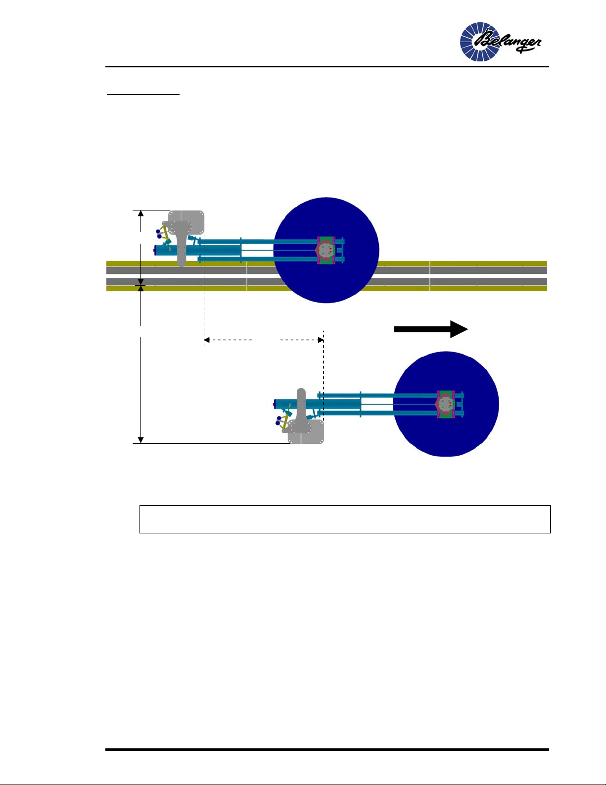
Tunnel Placement Overview
The placement images shown in this document are all laid out with the passenger side Stand closer to
the entrance of the tunnel. However, the most important factor is that the two Stands are off-set 78-1/2”
as far as tunnel depth. This means if your site is better suited with the driver side Stand closest to the
tunnel entrance, be sure to adhere to the stated off-set as shown in the diagrams.
Side View
121"
Entrance View
153"
204”
Operating Envelope
Direction of Travel
78-1/2" 190”
Minimum

QUICKFIRE® WRAP AROUND
12 Belanger, Inc. * 1001 Doheny Ct. * Northville, MI 48167 * Ph (248) 349-7010 * Fax (248) 380-9681 1MANUL825
Installation
Tunnel Placement Overview
When placing a piece of equipment, tunnel depth will vary from site to site. Be sure to allow an adequate operating envelope.
The “Posi-Stops can be adjusted to decrease the rotation distance if your site has limited space.
That will be covered later in this document.
1) Locate the two stand assemblies (legs) and determine which is the driver side and the
passenger side. See image above to assist in determination.
There are three traditional installation configurations for the QuickFire® Wrap Around.
•Standard, stand alone
•Staggered with a set of Wave Low Side Washers™
•Staggered with a set of Wave Full Side Washers™
The three traditional configurations are shown on the following pages.
2) Using a forklift, position the QuickFire® Wrap Around ™ stand assembles (legs) into their
appropriatetunnel location as shown on the following pages.
CAUTION
Be sure to clamp equipment securely to the forks of the forklift.
Do not stand under load while fork lift is in operation.
12°
33°
33°
12°
QUICKFIRE® WRAP AROUND
1MANUL825 Belanger, Inc. * 1001 Doheny Ct. * Northville, MI 48167 * Ph (248) 349-7010 * Fax (248) 380-9681 13
Installation
Tunnel Placement Overview
Standard, Standalone Configuration
Equipment around the Wrap should give ample room for the wheels to swing within the working
envelop
49-12” and the 103-1/2: dimensions are taken from the outside of base to the driver side edge of the inside guide rail
Heavy dotted lines show proper operating envelope
Note: Above image shown with booms and wash material installed to indicate operating
envelope required to function properly.
103-1/2" Direction of Travel
49-1/2"
78-1/2"
Minimum

QUICKFIRE® WRAP AROUND
14 Belanger, Inc. * 1001 Doheny Ct. * Northville, MI 48167 * Ph (248) 349-7010 * Fax (248) 380-9681 1MANUL825
Installation
Tunnel Placement Overview
Staggered with a set of Wave Low Side Washers™
Equipment around the Wrap should give ample room for the wheels to swing within the working
envelope.
For more information and details on installation of the Low Side Washer, Refer
to the Low Side Washer manual.
Note: Above image shown with booms and wash material installed to indicate operating
envelope required to function properly.
150" minimum
78-1/2” minimum
Direction of Travel
103-1/2"
49-1/2"
78-1/2"
Minimum
LSW
LSW

QUICKFIRE® WRAP AROUND
1MANUL825 Belanger, Inc. * 1001 Doheny Ct. * Northville, MI 48167 * Ph (248) 349-7010 * Fax (248) 380-9681 15
Installation
Tunnel Placement Overview
Staggered with a set of Wave Full Side Washers™
Equipment around the Wrap should give ample room for the wheels to swing within the working
envelope.
For more information and details on installation of the Full Side Washer, Refer
to the Full Side Washer manual.
Note: Above image shown with booms and wash material installed to indicate operating
envelope required to function properly.
103” minimum
24" 150" minimum
Direction of Travel
103-1/2"
49-1/2"
78-1/2"
Minimum
FSW
FSW

QUICKFIRE® WRAP AROUND
16 Belanger, Inc. * 1001 Doheny Ct. * Northville, MI 48167 * Ph (248) 349-7010 * Fax (248) 380-9681 1MANUL825
Installation
Positioning the Stands (Legs)
Note: When determining equipment placement, be sure to measure the distance from the next piece of
equipment leaving room for the boom to pivot.. Before positioning the leg assemblies, insert the leveling
bolts and tighten until flush with the bottom surface of the base plates. This will prevent cement dust from
getting in the treads.
1) Position the Passenger side Stand Assembly at the desired tunnel depth on the floor and
measure from the inside of the inside guide rail to the back of the passenger side base
plate. It is to be placed at a distance of 103-1/2” as shown below.
2) Position the driver side Stand Assembly at the desired tunnel depth on the floor and
measure from the inside of the inside guide rail to the back of the driver side base plate. It is
to be placed at a distance of 49-1/2” as shown below.
3) The two Stand Assemblies are to be offset 78-1/2” as shown below.
103-1/2"
49-1/2"
103
-
1/2
"
49-1/2"
Passen
g
er SideDriver Side
78-1/2"
Passen
g
er Side
Driver Side
Vehicle
Travel
Table of contents
Other Belanger Cleaning Equipment manuals

Belanger
Belanger FreeStyler User manual

Belanger
Belanger Quad Wave Mitter User manual

Belanger
Belanger FreeStyler User manual

Belanger
Belanger H2AIR ARCH User manual

Belanger
Belanger QuickFire Plus User manual

Belanger
Belanger Signature Series User manual

Belanger
Belanger DURAJET ARCH User manual

Belanger
Belanger HYDRO-HYBRID User manual

Belanger
Belanger Full Side Washer User manual

Belanger
Belanger SUDZAMELEON ARCH User manual


