Getinge FD1800 User manual

Always with you
GETINGE FD1800
TECHNICAL MANUAL
503712400
Service code 9817
Service code 9817

<Doc_TEC><Doc_503712400><Rel_B><Lang_EN>
Page 2 av 64

Page 3 av 64
<Doc_TEC><Doc_503712400><Rel_B><Lang_EN>
Contents
PREFACE_______________________________________________4
SAFETY REGULATIONS _________________________________5
General safety regulations ___________________________________ 5
In an emergency ___________________________________________ 5
Product liability ____________________________________________ 5
Isolator switch _____________________________________________ 5
INTRODUCTION ________________________________________6
Intended use of the machine_________________________________ 6
Attention symbols __________________________________________ 6
RCD ______________________________________________________ 6
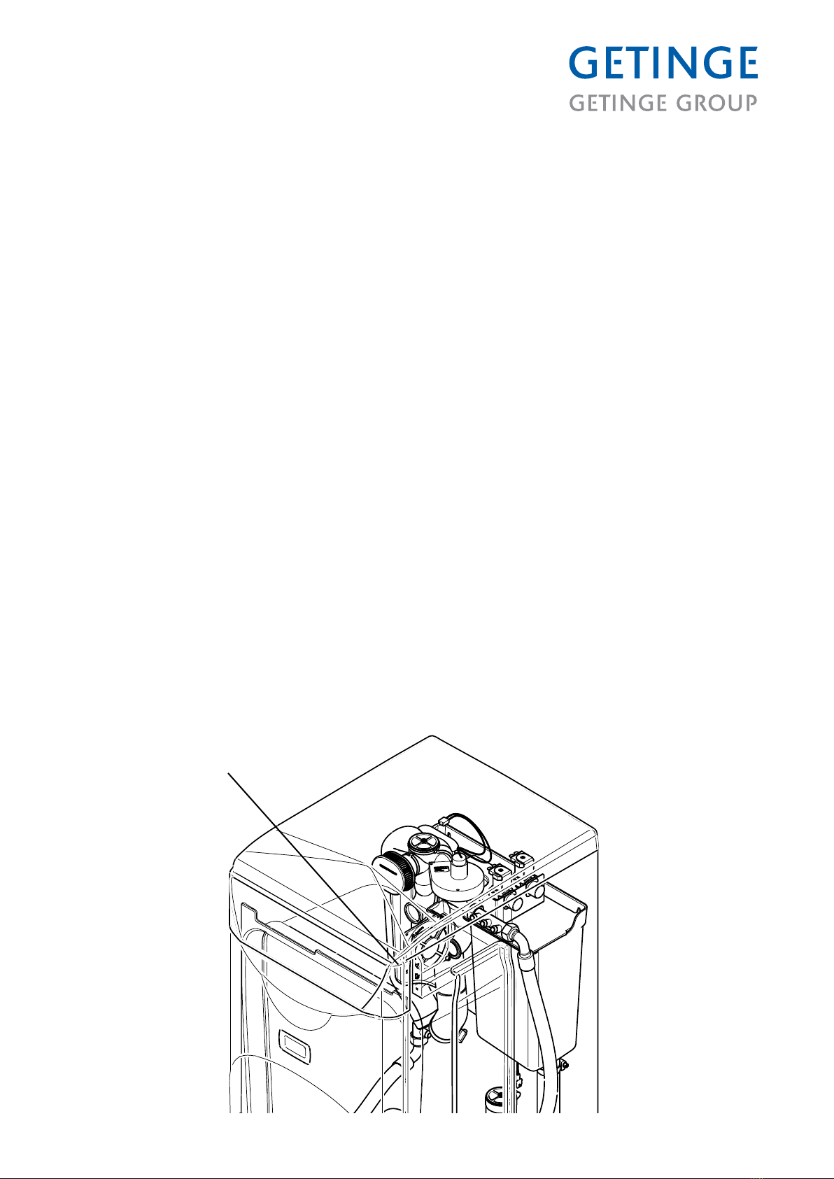
Description _____________________________________________7
General ___________________________________________________ 7
Function __________________________________________________ 7
P&I diagram _______________________________________________ 8
Cooling ___________________________________________________ 9
Inspection hole ____________________________________________ 9
Service program ________________________________________11
Function __________________________________________________ 11
Table of line numbers and line information _____________________ 13
The service program________________________________________ 19
Machine-independent variables, lines 00-09 ___________________ 22
Interval disinfection, line 31 __________________________________ 28
Inspection request, line 32___________________________________ 29
Dosage, line 33 ____________________________________________ 30
Empty container alarm, line 34 _______________________________ 30
Disinfection, lines 35 - 49____________________________________ 30
Tank and water, lines 50 - 55_________________________________ 32
Fault statistics, lines 60 - 63 _________________________________ 34
Program statistics, lines 70 - 74 ______________________________ 35
Function test, lines 80 - 83 __________________________________ 36
Fault indications ________________________________________42
Fault message _____________________________________________ 42
Acknowledging a fault message______________________________ 43
Resetting the machine ______________________________________ 43
Table of faults and possible actions___________________________ 44
PREVENTIVE MAINTENANCE ____________________________45
Periodic maintenance_______________________________________ 45
Function check ____________________________________________ 47
Draining the machine _______________________________________ 60
Opening the door in the event of a power failure________________ 61
Component list ____________________________________________ 62

<Doc_TEC><Doc_503712400><Rel_B><Lang_EN>
Page 4 av 64
PREFACE
This technical manual is intended for maintenance and service personnel working with
the Tornado/FD1800 usher disinfector.
The service manual is divided into the following sections:
• Safety regulations
• Technical data
• Description of the design and operation of the machine
• Software description and menu tree
• Preventive maintenance
• Fault indications and troubleshooting
• Repair and adjustments
• Electrical diagram
The purpose of the technical manual is to provide information for the maintenance and
service personnel whose job it is to ensure safe operation with optimum efciency.
Before starting work on the machine, the maintenance and service personnel must have
read the safety instructions in this manual and familiarized themselves with the operation
of the machine and its safety instructions.
Read the safety instructions in the technical manual before starting work on
the machine.
The information in this manual describes the machine as dispatched from Getinge.
There may be differences due to customization.
The machine is accompanied by the following documentation:
• User manual
• Installation manual
• Technical manual (this manual)
• Spare parts list
Getinge reserves the right to change the specication and design without prior notice.
The information in this manual was up to date on the date of issue of the manual.
© Copyright
The content of this manual must not be copied, in whole or in part,
without the written consent of Getinge.

Page 5 av 64
<Doc_TEC><Doc_503712400><Rel_B><Lang_EN>
SAFETY REGULATIONS
This machine has been designed with a number of built-in safety devices. To avoid
injury, it is highly important not to bypass or disable these safety devices.
General safety regulations
• Take care when handling the chemical agent used in the machine.
Read the details on the container or contact the manufacturer:
- if the agent comes into contact with the operator’s eyes or skin or if the vapors
are breathed in, etc.
- about storing the agent and disposing of empty containers.
• The machine must be connected in accordance with the installation instructions.
• Read the instructions thoroughly before use.
• The machine may only be operated by adults.
• Installation and service work must be done by personnel trained for this machine.
• The door locks of the machine must never be bypassed.
• Leakage in the system, due to a worn door seal for example, must be repaired
without delay.
• Before repair or service work is done, the personnel concerned must study the
relevant documentation and service manuals.
• Before welding begins on or close to the machine, all wiring connected by plugs
and sockets must be disconnected from all circuit boards of the control system.
• The machine must not be hosed down with water.
• Take care when using corrosive detergents.
• Precautions must be taken with hot water and steam.
• Run a program before starting servicing work. If this is not possible, disinfect the
machine with disinfectant before starting servicing work.
In an emergency
• Switch off the main switch.
• Close shutoff valves in the water and (where present) steam supply lines.
Product liability
Any modication or incorrect use of the equipment without the approval of Getinge
Disinfection AB invalidates Getinge Disinfection AB’s product liability.
This product was manufactured by:
GETINGE DISINFECTION AB
Ljungadalsgatan 11, Box 1505
SE-351 15 Växjö, Sweden
Isolator switch
The machine must be tted with a separate isolating device in the electric power supply.
The isolating device must be easily accessible on a wall close to the machine.

<Doc_TEC><Doc_503712400><Rel_B><Lang_EN>
Page 6 av 64
INTRODUCTION
Intended use of the machine
Flusher disinfector for emptying, cleaning and disinfecting bowls, urine bottles and
buckets.
To meet the requirements of EN ISO 15883, the items must be placed in the proper
holder, recommended by Getinge Disinfection AB.
The customer is responsible for ensuring that an Installation Qualication and a
Performance Qualication according to ISO 15883 are carried out before the product is
put into use.
Attention symbols
Some of the warnings, instructions and advice in this manual are so important that we
use the following special symbols to draw attention to them. The symbols and designs
used are:
This symbol indicates a warning in the technical manual. It warns of a hazard
that may lead to more or less severe injury and in certain cases mortal
danger.
It also highlights warnings of possible damage to the machine.
This symbol highlights a warning in the text of the service manual dealing
with the handling of components sensitive to ESD. The hazard that it warns
about may result in damage to hardware and/or circuit boards.
If the machine has not been used for 72 hours, the steam generators and
circulation pump must be drained. This must only be done by authorized
service personnel.
Warning, hot surfaces. When the processor is finished, the surfaces can be
very hot. Be careful when touching surfaces.
Warning: electrically live parts
Contamination risk
Service personnel can be infected by parts in the machine.
RCD
We recommend using a residual current device (RCD) with the machine.

Page 7 av 64
<Doc_TEC><Doc_503712400><Rel_B><Lang_EN>
Description
General
The usher disinfector is designed for cleaning and disinfecting circulation items such
as bedpans and urine bottles. In this context, disinfection means killing all vegetative
bacteria, fungal spores and viruses, but not bacterial spores. A description of the
mechanical design and general functions of the machine is given the instruction manual.
This section contains a general description of the control system and schematic diagrams
of the machine. For detailed information about the software and its settings, see the
chapter entitled “Software description and settings”.
Function
The items are cleaned by ushing with cold and hot water through xed and rotating
nozzles. The water is drawn by a pump from the machine tank and fed to the ushing
housing. The waste outlet of the machine is connected to the normal waste pipe system.
The items are disinfected with steam and then cooled by ushing with water (the cooling
phase can be eliminated by programming the machine accordingly).

<Doc_TEC><Doc_503712400><Rel_B><Lang_EN>
Page 8 av 64
P&I diagram
M01
M
TS
B20
LA
B02
M04
M
LA
B04
M
M03
LSA
B01A
LSA
B01B
LSA
B01C
LA
B05
M
GS
S03
GS
S05
M18 TIA/TIR
B07
Instrument funktioner enl. ISO 3511.
Komponent märkning enl. IEC 750.
Instrument functions acc. to. ISO 3511.
Component marking acc. to IEC 750.
=OPTIONS
G 1/2"
G 1/2"
Ø110 or 90mm.
M
GS
S05
GS
S03
M16
LA
B06
M
M07
ZXX
LA
B03
M02
M
Replace E01 and B20.

Page 9 av 64
<Doc_TEC><Doc_503712400><Rel_B><Lang_EN>
Safe and simple
Disinfection is fully automatic
• safety and reliability can be kept high by continuous monitoring of the process.
• the dosing of descaler, the temperature and the disinfection time can all be altered
with great precision to suit different conditions.
• the built-in service program makes troubleshooting and servicing far easier.
Operation is simple and the control buttons are few and clearly marked.
Simple service and installation
Valves and the electrical equipment are easily accessible for inspection and service from
the front and from above.
Cooling
Cooling with ventilator (optional)
The items can be cooled by the ventilator fan sucking the warm air out from the chamber.
Internal cooling (optional)
Internal cooling takes water from the tank and the standard water supply.
This method is not recommended according to EN ISO 15883.
Inspection hole
The inspection hole is located in the front left corner of the chamber.
In order to access the inspection hole, remove the front plate.
Inspection hole

<Doc_TEC><Doc_503712400><Rel_B><Lang_EN>
Page 10 av 64
The programs
Programs, standard set:
P1 Economy program for lightly soiled items.
P2 Normal program for normally soiled items.
P3 Intensive program for heavily soiled goods.
The following programs can also be selected:
P4 Normal program with detergent dosing (option).
P5 Intensive program with detergent dosing (option).
P6 Normal program with detergent dosing in tank and/or spray dosing in the chamber
(option).
P7 Intensive program with detergent dosing and/or spray dosing in the chamber (option).
P8 Rim ushing program.
P10 Extra intensive program to meet the requirements of HTM 2030 (option).
P11 Extra intensive program with detergent dosing in tank, to meet the requirements of
HTM 2030 (option).
P12 Extra intensive program with detergent dosing in tank and/or spray dosing in the
chamber, to meet the requirements of HTM 2030 (option).
P14 Extra Extra intensive program to meet the requirements of Koller W and HTM 2030.
P15 Extra Extra intensive program with detergent dosing in tank or pump, to meet the
requirements of Koller W and HTM 2030 (option).
P16 Extra Extra intensive program with detergent dosing in tank and/or spray dosing in
the chamber, to meet the requirements of Koller W and HTM 2030 (option).
P18 Cooling phase with combined rinse-aid and descaler dosing in tank (option).
P19 Cooling phase with rinse-aid dosing in pump (option).
P20 Cooling phase with rinse-aid dosing in tank.
The process starts when the desired program is chosen (the yellow button by LL lights
up). (The normal program takes about ve minutes.)
When the process is complete, the green lamp at M M lights up and the door can be
opened (manual door).
Machine with automatic door opens when the IR diode, , is activated for at least
1 second.
The items may be hot at the end of the program. If the temperature of the
items is above 60 °C, the display shows U7.

Page 11 av 64
<Doc_TEC><Doc_503712400><Rel_B><Lang_EN>
Service program
Function
In the service program, maintenance and service personnel can set parameters which
control the operation of the machine. These parameters are divided into the following
groups:
• Machine-independent settings
• Conguration
• Program selection
• Interval disinfection
• Inspection request
• Dose size
• Empty container alarm
• Disinfection
• Tank and water
• Fault statistics
• Program statistics
• Function test
• Activation of inputs and outputs
• Switching of inputs and outputs
The facility for changing line information is protected by authorization codes, so as not
to put the operation of the machine at risk. There are four passwords with different levels
of authorization:
• LevelA for users; display only (code 0000)
• LevelB for users; change (code 2000)
• LevelC for service personnel, change
• LevelD for service personnel, critical settings.
You can always view all higher-level program lines without the authorization code for
those levels. The code only protects against changes.
The operator communicates with the service program via the pushbuttons on the front
panel and via the display.
The information in the memory of the machine is structured as a number of lines,
where every line has a two-digit line number (00 - 99). On every line there is either line
information or a control for a certain function, e.g.:
On program line 11 you can switch child safety on or off.
Line Parameter Basic setting Setting range Authorization
11 Child safety 0 0=No, 1=Yes BCD
A line can also contain several sub-line numbers. Each sub-line has a particular function,
e.g.:
On program line 30, you can choose, with the aid of the sub-lines, which program (of up
to 25) will start when a button or a combination of buttons is pressed.

<Doc_TEC><Doc_503712400><Rel_B><Lang_EN>
Page 12 av 64
Line Sub-line Parameter Basic setting Setting range Authorization
30 11 Program selection, button 1 1 00-25 CD
30 21 Program selection, button 2 2 00-25 CD
30 31 Program selection, buttons 2+5 4 00-25 CD
30 41 Program selection, button 3 3 00-25 CD
30 51 Program selection, buttons 3+5 5 00-25 CD
30 61 Program selection, button 4 8 00-25 CD
The table on the pages that follow lists all the line and sub-line numbers of the machine.
This section also describes how to work with the service program. This is followed by a
detailed description of each line number and its information.

Page 13 av 64
<Doc_TEC><Doc_503712400><Rel_B><Lang_EN>
Table of line numbers and line information
Line Sub-
line
Parameter Basic
setting
Setting range
Authorization
Lines 00-09: Machine-independent variables
0 - Authorization code 0000-9999 ABCD
1 - Checking and retrieving settings 1=Basic, 2=Factory, 3=Work CD
2 - Machine type FD1800, etc. -
3 01 Program version (main version) 00.=00-99 -
3 02 Program version (sub-version) .00=00-99 -
3 03 Program version (test version) 00-99 -
3 04 Program protocol 109 - -
4 - Serial number 0-999999 -
5 - Language 1 1=DE, 2=SE, 3=EN, 4=FR, 5=IT,
7=DK, 8=HU, 9=ES, 10=CZ,
11=PL
CD
6 01 Date, year 97 00-99 BCD
6 02 Date, month 01 01-12 BCD
6 03 Date, day 01 1-31 BCD
7 01 Time, hours 00 00-24 BCD
7 02 Time, minutes 00 00-59 BCD
8 - Demo 0 0 = Not active, 1 = Active CD
9 01 Address, interface 1 0=None, 1=RS-232, 2=RS-485 CD
9 02 Address, network address 1 0-9999 CD
Lines 10-29: Configuration
10 - Start-up code 0 0 = Not active, 1 = Active CD
11 - Child safety 0 0 = Not active, 1 = Active BCD
12 - Disinfection configuration 1 1=Normal, 2=Spare BCD
13 01 Dosing (button 2-3) 1 1=Manual, 2=Automatic BCD
14 01 Sound on door closing 1 0=None, 1=50 ms, 100 ms CD
14 02 Door type 1 1=Manual, 2=Automatic CD
14 03 IR sensor interval 1.0 1-9.9 sec DE
15 01 Acoustic alarm 0 0 = Not active, 1 = Active CD
16 01 Feedback activation 0 0 = Not active, 1 = Active DE
16 02 Feedback interval 0 0-255 DE
17 - Temperature scale 1 1=Celsius, 2=Fahrenheit CD
19 - Mains frequency 1 1=50 Hz, 2=60 Hz CD
20 - Pump starting time 0.0 0-5.0 seconds CD
21 - Temperature indication (Red LED) 1 1=Temperature error, 2=Heating CD
22 - Temperature, condensate cooling 60 0-99 °C CD
23 - Time to crack open 2.0 0-9.9 seconds CD
24 - Waiting time cracked open 0 0-1800 seconds CD
28 - Run flushing program 0 0-20 CD
29 - Set flushing program 1 1-3 CDE

<Doc_TEC><Doc_503712400><Rel_B><Lang_EN>
Page 14 av 64
Line Sub-
line
Parameter Basic
setting
Setting range
Authorization
Line 30: Program selection
30 11 Program selection button 1 1
00=No program, 01-20 Program no.
CD
30 12 Program name button 1 Economy program CD
30 21 Program selection button 2 2
00=No program, 01-20 Program no.
CD
30 22 Program name button 2 Normal program CD
30 31 Program selection buttons 2+5 4
00=No program, 01-20 Program no.
CD
30 32 Program name button 2 Normal+Detergent CD
30 41 Program selection button 3 3
00=No program, 01-20 Program no.
CD
30 42 Program name button 3 Intensive program CD
30 51 Program selection buttons 3+5 5
00=No program, 01-20 Program no.
CD
30 52 Program name button 3+5 Intensive program+Detergent CD
30 61 Program selection button 4 8
00=No program, 01-20 Program no.
CD
30 62 Program name button 4 Rim flushing CD
30 71 Set pedal 2 0-25 CDE
30 72 Name pedal 2 0-10 CDE
30 81 Set pedal + button 5 0 0-25 CDE
30 82 Name pedal + button 5 3 0-10 CDE
30 91 Program selection IR 2 CD
30 92 Program name IR 2 CD
30 101 Program name IR + button 5 0 CD
30 102 Program IR + button 5 3 CD
30 150 IR function 0 0=No IR, 1=Open/close door,
3=Start program
CD
Line 31: Interval disinfection
31 01 Interval disinfection 0 0 = Not active, 1 = Active CD
31 02 Interval disinfection programs 1 00=No program 01-20=Program
no.
CD
31 03 Limit for interval disinfection 9999 0-9999 program CD
31 04 Processes remaining to interval
disinfection
- 0-9999 program CD
31 05 Reset interval disinfection - 0=Zero BCD
Line no. 32: Inspection request
32 01 Processing of inspection requests 1 0=None, 1=Warning, 2=Stop CD
32 02 Acknowledgement of inspection
requests
- 0=Acknowledged CD
32 03 Counter type for inspection requests 1 1=Connection hours,
2=Number of programs
CD
32 04 Limit for inspection requests 9999 0-9999 CD
32 05 Counter for inspection request - 0-9999 -
Line 33: Dose size
33 01 Dosing time, descaling 6 0-99 seconds BCD
33 02 Dosing time rinse-aid 4 0-99 seconds BCD
33 03 Dosing time, process agent 30 0-99 seconds BCD
33 04 Dosing time spray agent 0.7 0-99 seconds BCD

Page 15 av 64
<Doc_TEC><Doc_503712400><Rel_B><Lang_EN>
Line Sub-
line
Parameter Basic
setting
Setting range Authorization
Line 34: Empty container alarm
34 01 Alarm descaling agent 0125 00=no alarm, 01.99=warning,
no. of programs after low level,
02=stop
CD
34 01.01 Alarm descaling agent
processes remaining
25 0-99 CDE
34 02 Alarm chemical agent 0200 00=no alarm, 01.99=warning,
no. of programs after low level,
02=stop
CD
34 02.01 Alarm chemical agent processes
remaining
00-99 DE
34 03 Alarm rinse-aid 0125 00=no alarm, 01.99=warning,
no. of programs after low level,
02=stop
CD
34 03.01 Alarm rinse-aid processes remaining 25 0-99 CDE
34 04 Alarm, process agent 0110 00=no alarm, 01.99=warning,
no. of programs after low level,
02=stop
CD
34 04.01 Alarm process agent processes
remaining
10 0-99 CDE
34 05 Alarm spray agent 0110 00=no alarm, 01.99=warning,
no. of programs after low level,
02=stop
CD
34 05.01 Alarm spray agent processes remaining 10 0-99 CDE
Lines 35-49: Disinfection
35 - Normal disinfection method 1 1=D-T, 2=C-T, 3=D-C-D,
4=C-K-D
CD
36 - Reserve disinfection method 1 1=D-T, 2=C-T, 3=D-C-D,
4=C-K-D
CD
38 - Lower disinfection temperature 91 80-95 ˚C CD
39 - Upper disinfection temperature 93 80-97 ˚C CD
40 - Disinfection temperature 85 80-95˚C CD
41 - Disinfection time 60 0-1800 seconds CD
42 - Max preheat time, steam generator 50 0-99 seconds CD
43 - Power sharing, steam generator 1 0=Not active, 1=Active CD
44 1 Cooling method 1 0=None, 1=Internal, 2=External,
3=Extended
CDE
44 2 Global external cooling time 120 1-180 sec CDE
44 3 Global extended cooling (after process) 120 0-180 sec CDE
45 1 Handling auto-disinfection 0 0=None, 1=Warning, 2=Warning
+ autostart
CDE
45 2 Auto-disinfection starts from 8 Time 0-23 CDE
45 3 Auto-disinfection permitted until 20 Time 0-23
46 - Disinfection to A0 0 0, 60, 600 CDE
48 - Dosage, chemical agent 70 0-99 seconds CD
49 - Chemical action time 0 0-600 seconds CD

<Doc_TEC><Doc_503712400><Rel_B><Lang_EN>
Page 16 av 64
Line Sub-
line
Parameter Basic
setting
Setting range
Authorization
Lines no 50-57: Tank and water
50 - Tank level at rest 2 1=Empty tank, 2=Level B,
3= Level C
CD
51 - Water type, filling at rest 1 1 = cold, 2 = hot, 3 = cold and hot CD
52 - Mix ratio 50 0-100 % cold water CD
53 01 Type of rim flushing 1 0=None, 1=Internal CD
54 - Addition of softened water 0 0=none, 1=internal CD
55 - Time for soft water 5 0-99 seconds CD
56 - Flushing time cooling 0 0.0-99.9 seconds
replaces line 45 in Eprom ver. 1.21
CD
57 01 Flushing time in the instruction
“Pulsed flushing to level”
1.5 0.0-99.9 seconds CD
57 02 Pause time in indication
“Pulsed flushing to level”
1.0 0.0-99.9 seconds CD
57 03 Pulses in the instruction
“Pulsed flushing to level”
5 0.0-99.9 seconds CD
Lines 60-63: Fault statistics
60 - Time of fault 0-9999 seconds -
61 - Instruction for last fault 0=not in flushing program,
1-999=program line
-
62 - Counter, total number of faults 0-9999 -
63 01 Counter for fault code F1 0-99 faults CD
63 nn Counter for fault codes Fnn 0-99 faults CD
Lines 70-74: Program statistics
70 - Max disinfection temperature 80-99 ˚C -
71 - Program time, last process 0-9999 seconds -
72 - Program time, total 0-99999 seconds -
73 - Counter for number of processes 0-99999 -
74 01 Counter, program 1 0-9999 CD
74 nn Counter, program nn 0-9999 CD
Line 80: Function test
80 - Display test 1=activate LEDs and display CD
81 01 Read input 1 (max 12) 0=off, 1=on -
81 nn Read input nn 0=off, 1=on -
82 01 Control, outputs 1 (max. 16) 0 = off, 1 = on CD
82 nn Modulation output. nn 0=off, 1=on CD
83 01 Read temperature C/F 0-250 ˚C/32-302 ˚F -
83 02 Reading temperature C/F independent 0-250 ˚C/32-302 ˚F -
85 - Save config. in flash
86 - Load config. from flash
87 - Calibrate AD
88 - Calibrate independent AD

Page 17 av 64
<Doc_TEC><Doc_503712400><Rel_B><Lang_EN>
Line Sub-
line
Parameter Basic
setting
Setting range
Authorization
Row 96: Activation inputs
96 01 Activation, level A 1
0=input not active, 1=input active
CD
96 02 Activation, level B 1
0=input not active, 1=input active
CD
96 03 Activation, level C 1
0=input not active, 1=input active
CD
96 04 Activation, descaler, low level 1
0=input not active, 1=input active
CD
96 05 Activation descaler empty 0
0=input not active, 1=input active
CD
96 06 Activation chemical agent low level 0
0=input not active, 1=input active
CD
96 07 Activation chemical agent empty 0
0=input not active, 1=input active
CD
96 08 Activation rinse-aid low level 0
0=input not active, 1=input active
CD
96 09 Activation rinse-aid empty 0
0=input not active, 1=input active
CD
96 10 Activation, process agent, low level 0
0=input not active, 1=input active
CD
96 11 Activation, process agent, empty 0
0=input not active, 1=input active
CD
96 12 Activation spray agent low level 0
0=input not active, 1=input active
CD
96 13 Activation spray agent empty 0
0=input not active, 1=input active
CD
96 14 Activation, leakage sensor 1
0=input not active, 1=input active
CD
96 15 Activation, door closed 1
0=input not active, 1=input active
CD
96 16 Activation, door closed 1
0=input not active, 1=input active
CD
96 17 Door open (FD1810) 1
0=input not active, 1=input active
CDE
96 20 Safety switch door closing (FD1810) 1
0=input not active, 1=input active
CDE
96 21 Pedal (FD1810) 0
0=input not active, 1=input active
CDE
Line 97: Activation outputs
97 01 Activation, pressure pump 1
0=input not active, 1=input active
CD
97 02 Activation, steam generator 1 0=input not active, 1=input active CD
97 03 Activation, cold water 1 0=input not active, 1=input active CD
97 04 Activation, hot water 1 0=input not active, 1=input active CD
97 05 Activation, soft water 0 0=input not active, 1=input active CD
97 06 PE system (rotary nozzle) 0 0=input not active, 1=input active CDE
97 07 SP system (spray nozzle) 0 0=input not active, 1=input active CDE
97 08 Extra nozzle 0 0=input not active, 1=input active CDE
97 10 Activation, pump, descaling 1 0=input not active, 1=input active CD
97 11 Activation pump chemical agent 0 0=input not active, 1=input active CD
97 12 Activation pump rinse-aid 0 0=input not active, 1=input active CD
97 13 Activation, pump, process agent 0 0=input not active, 1=input active CD
97 14 Activation pump spray agent 0
0=input not active, 1=input active
CD
97 15 Activation, extra element, steam
generator
1
0=input not active, 1=input active
CD
97 16 Activation, condensate cooler 0
0=input not active, 1=input active
CD
97 17 Activation, external cooling. 0
0=input not active, 1=input active
CD
97 23 Activation relay corresp. to yellow LED 0
0=input not active, 1=input active
CD
97 24 Activation relay corresp. to red LED 0
0=input not active, 1=input active
CD
97 25 Rim flushing 0
0=input not active, 1=input active
CDE

<Doc_TEC><Doc_503712400><Rel_B><Lang_EN>
Page 18 av 64
Line Sub-
line
Parameter Basic
setting
Setting range Authoriza-
tion
Line 98: Input connections
98 01 Connection, level A 1 1-99 DE
98 02 Connection, level B 2 1-99 DE
98 03 Connection, level C 3 1-99 DE
98 04 Conn., descaler, low level 5 1-99 DE
98 05 Conn., descaler, empty 15 1-99 DE
98 06 Connection chemical agent low level 5 1-99 DE
98 07 Connection chemical agent empty 16 1-99 DE
98 08 Connection rinse-aid low level 6 1-99 DE
98 09 Connection rinse-aid empty 16 1-99 DE
98 10 Conn., process agent, low level 7 1-99 DE
98 11 Connection process agent empty 16 1-99 DE
98 12 Conn., spray agent, low level 8 1-99 DE
98 13 Connection spray agent empty 16 1-99 DE
98 14 Conn., leakage sensor 4 1-99 DE
98 16 Conn., door closed 11 1-99 DE
98 17 Connection, door open 12 1-99 DE
98 20 Safety switch door closing (FD1810) 13 1-99 DE
98 21 Pedal (FD1810) 14 1-99 DE
Line 99: Output connections
99 01 Conn., pressure pump 6 1-99 DE
99 02 Conn., steam generator 7 1-99 DE
99 03 Conn., cold water 1 1-99 DE
99 04 Conn., hot water 2 1-99 DE
99 05 Connection soft water 8 1-99 DE
99 06 PE system (rotary nozzle) 14 1-99 DE
99 07 SP system (spray nozzle) 13 1-99 DE
99 08 Extra nozzle 15 1-99 DE
99 10 Connection pump, descaler 8 1-99 DE
99 11 Connection pump chemical agent 7 1-99 DE
99 12 Connection pump rinse-aid 5 1-99 DE
99 13 Connection pump, process agent 10 1-99 DE
99 14 Connection pump spray agent 9 1-99 DE
99 15 Connection, extra element, steam
generator
12 1-99 DE
99 16 Connection, condensate cooler 3 1-99 DE
99 17 Connection, external cooling 4 1-99 DE
99 23 Connection relay corresp. to yellow LED 3 1-99 DE
99 24 Connection relay corresp. to red LED 4 1-99 DE

Page 19 av 64
<Doc_TEC><Doc_503712400><Rel_B><Lang_EN>
The service program
NOTE:
You must enter your authorization code before you can change anything in the
programming; see under Authorization code.
If the reading is flashing it can be changed. If it is not flashing, either it cannot be
changed or you do not have the authority to change it.
Accessing the service program
First press and hold . Then press and keep pressing both buttons for 10 seconds.
The machine is now in service mode and line numbers !! appear on the display. Note
that the correct authorization code must be entered before you can change the values
displayed (see under “Authorization code”).
+Enter the service program (keep both buttons pressed for 10 seconds).
+Quit the service program (keep both buttons pressed for 4 seconds).
You must be in line number mode to quit the service program.
Increase line number or numerical value. For fast feed, hold the button down.
Decrease line number or numerical value. For fast feed, hold the button down.
Cancel entry without saving the new value.
Jump back to the previous display window reading.
Go to sub-line /go to numerical value/save numerical value/go to next numeri-
cal value.
Operator password (line number 0)
The machine has four authorization levels:
• Level A for users; display only (code 0000)
• Level B for users; change (code 2000)
• Level C for service personnel, change
• Level D for service personnel, critical settings.
The code only protects against changes.
The authorization code (password) is on line 0 and is entered in the same way as other
numerical values, as described in the next section.

<Doc_TEC><Doc_503712400><Rel_B><Lang_EN>
Page 20 av 64
Check or change a numerical value on a line without a sub-line number
• Press (increase line number) or (reduce line number) so the display shows
the right line number. Holding down the button scrolls the value up or down for as
long as the button is pressed.
• Press: . The numerical value for the line number is shown. The value ashes if
you are authorized to change it.
• To change the numerical value:
- If you want to change the value, press (increase) or (reduce) until the
correct value is shown. Press to store the new value in the memory of the
computer.
- If the value has four digits, the two digits on the left ash rst.
Change them and press . The two digits on the right now ash and can be
changed in the same way.
- When nished, press once more to show the line number again.
• You can also just check the numerical value without changing it:
- When you are nished, press . This brings you back to the line number.
!#
The line number always
appears to the left on
the display
=!
The numerical value
appears to the right
on the display
Value as two digits
=!##
Value as four digits
First change the two
digits to the left…
…and then the two to
the right
!#
Line numbers always
appear to the left on the
display.
!#
!
!#
=!##
The numerical value is
shown to the left on the
bottom line of the display.
Table of contents
Other Getinge Cleaning Equipment manuals

Getinge
Getinge 86 SERIES User manual

Getinge
Getinge 46-2 User manual

Getinge
Getinge 86 SERIES User manual

Getinge
Getinge 88-SERIES User manual

Getinge
Getinge Decomat 4656 User manual

Getinge
Getinge Castle 7900 User manual

Getinge
Getinge Decomat 9900 Series Operating instructions

Getinge
Getinge S-606 User manual
Popular Cleaning Equipment manuals by other brands

Nilfisk-Advance
Nilfisk-Advance MultiFoamer Pegasus 120 Directions for use

Ultrasonic
Ultrasonic UP3218 Operator and maintenance manual

ERRECOM
ERRECOM JetGun user manual

Belanger
Belanger FreeStyler E-1032 owner's manual

cedis
cedis e 125.DUS operating instructions

LEHMANN
LEHMANN QLEEN PURASTART E quick guide