NuTone Heat-A-Ventlite 9965-R02 User manual

1
INSTA ATION INSTRUCTIONS
READ & SAVE THESE INSTRUCTIONS!
Heat-A-Ventlite®
(with Night ight)
MODE : 9965-R02
FOR BEST RESU TS
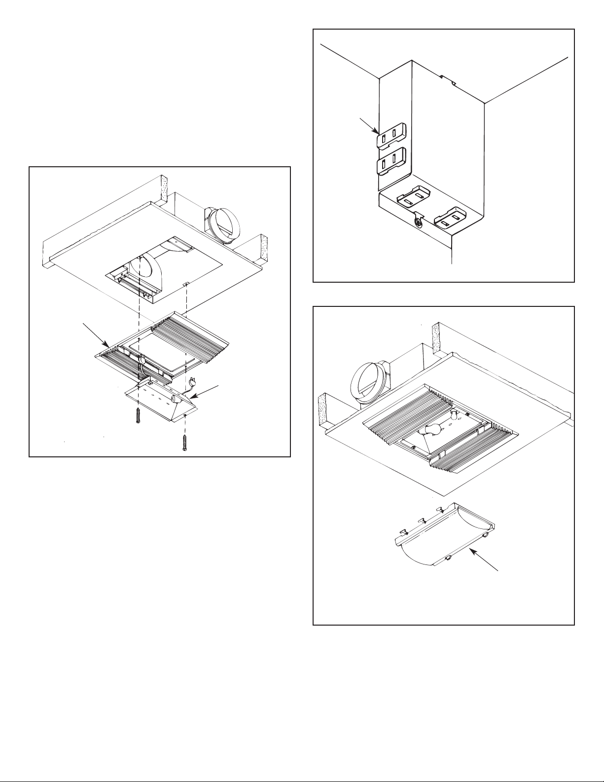
In a new construction site, install the housing (complete
with heater and ventilator) during rough-in construction of the
building. The light assembly and the grille should be installed
when the finished ceiling is in place.
Installation in an existing, finished building requires an
accessible area (attic or crawl space) above the planned
location. See “INSTALLATION IN EXISTING
CONSTRUCTION.”
Do not install closer than 12 inches to a vertical surface.
Do not install over tub or shower enclosure.
•
For installation in sloped ceilings up to 12/12 pitch.
•
Ductwork must point up.
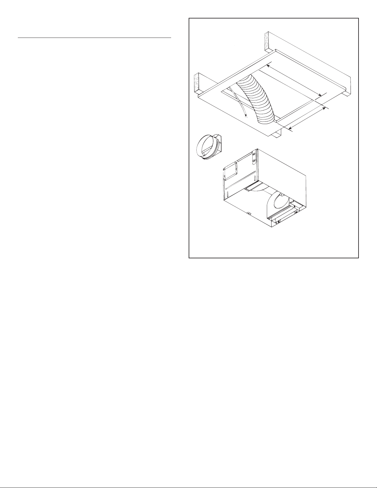
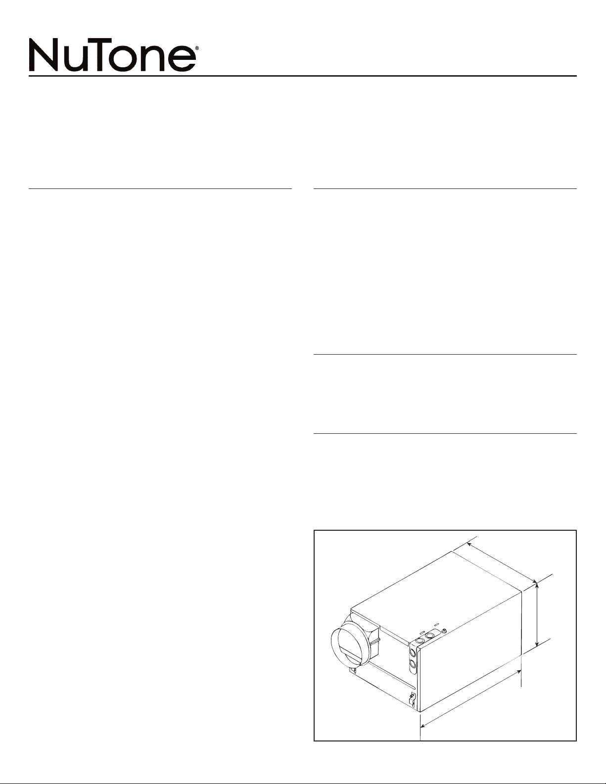
UNIT DIMENSIONS
Refer to Figure 1 for housing's dimensions.
NOTE: If there will be a finished second floor above,
the Model 9965 housing requires a minimum of 2" x 8"
joist construction for mounting.
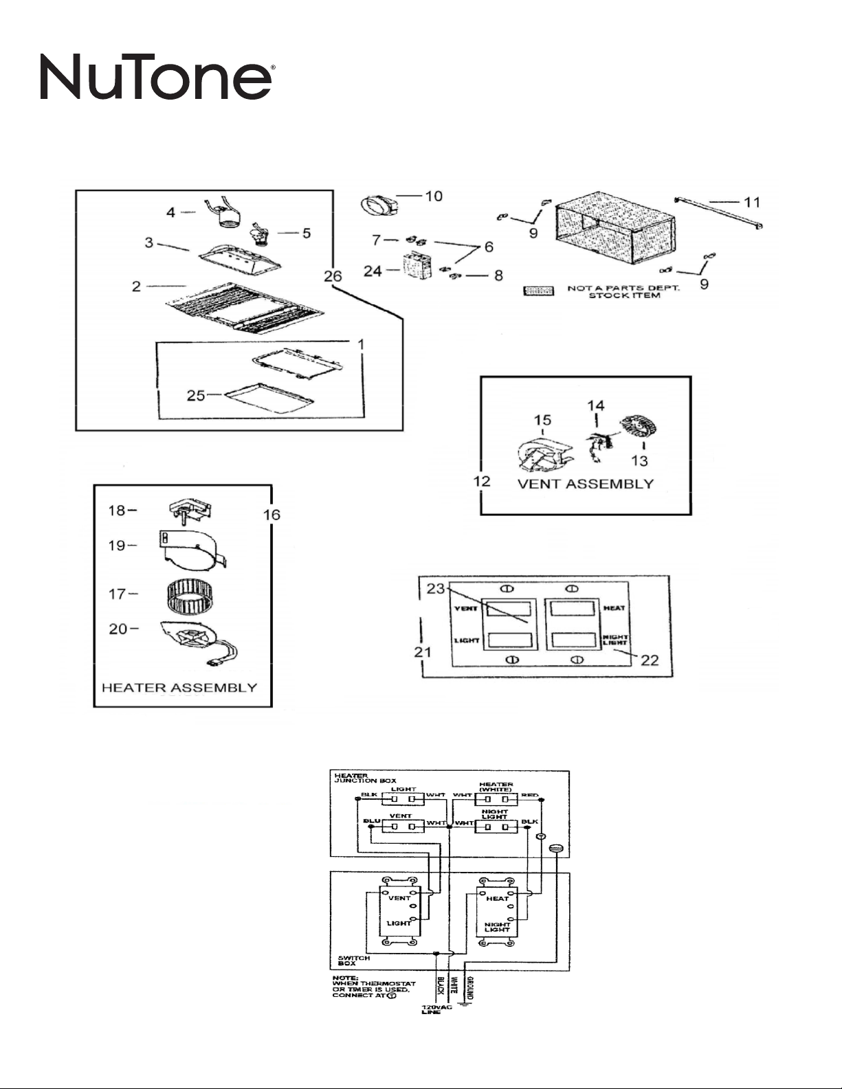
WIRING AND DUCTWORK
1. Run the required wiring during rough-in stage of
construction.
2. Total connected load: 1730 watts.
3. lan to run 120vAC, 60 Hz wiring (with ground) on a
separate 20 Amp circuit from a power source, through
the provided wall switch, to the housing's junction box.
See wiring diagram.
4. Use 4" round duct.
FIGURE 1
7
3
⁄
4
"
14"
9
3
⁄
4
"
IMPORTANT INSTRUCTIONS
READ ALL INSTRUCTIONS BEFORE INSTALLING OR USING THIS
HEATER.
To reduce the risk of fire, electric shock, or injury to persons, observe the
following:
1. Use this unit only in the manner intended by the manufacturer. If you
have questions, contact the manufacturer at the address or
telephone number listed in the warranty.
2. Before servicing or cleaning unit, switch power off at service panel
and lock the service disconnecting means to prevent power from
being switched on accidentally. When the service disconnecting
means cannot be locked, securely fasten a prominent warning
device, such as a tag, to the service panel.
3. Installation work and electrical wiring must be done by a qualified
person(s) in accordance with all applicable codes and standards,
including fire-rated construction codes and standards.
4. When cutting or drilling into wall or ceiling, do not damage electrical
wiring and other hidden utilities.
5. This heater is hot when in use. To avoid burns, do not let bare skin
touch hot surfaces. Keep combustible materials, such as furniture,
pillows, bedding, papers, clothes, etc. and curtains at least 3 feet
(0.9 m) from the front of the heater.
6. Extreme caution is necessary when any heater is used by or near
children or invalids and whenever the heater is left operating and
unattended.
7. Do not operate any heater after it malfunctions. Disconnect power at
service panel and have heater inspected by a reputable electrician
before reusing.
8. Do not use outdoors.
9. To disconnect heater, turn controls to off, and turn off power to heater
circuit at main disconnect panel (or operate internal disconnect
switch, if provided).
10.Do not insert or allow foreign objects to enter any ventilation or
exhaust opening, as this may cause an electric shock or fire, or
damage the heater.
11. To prevent a possible fire, do not block air intakes or exhaust in any
manner.
12. A heater has hot and arcing or sparking parts inside. Do not use it in
areas where gasoline, paint, or flammable vapors or liquids are used
or stored.
13. Use this heater only as described in this manual. Any other use not
recommended by the manufacturer may cause fire, electric shock, or
injury to persons.
14. Install heater at least 12 inches from floor or any adjacent wall.
15. To avoid electrical shock: Do not install unit in a tub or shower
enclosure or any location where it may come in contact with water.
Never place a switch where it can be reached from a tub or shower.
16. This product is designed for installation in ceilings up to a 12/12 pitch.
Duct connector must point up. DO NOT MOUNT THIS RODUCT IN
A WALL.
17. Do not connect heater to dimmer switch or speed control.
18. Ducted fans must always be vented to the outdoors.
19. rovide a separate 20 AM circuit. Use 12 GA. power cable of type
which meets code.
20. This product must be grounded.
SAVE THESE INSTRUCTIONS
30042496C

2
FIGURE 5
DUCT CO AR
INSTA ATION IN
NEW CONSTRUCTION
PREPARATION
1. Install hanger bar brackets in slots in housing. (See Fig. 3)
Do not tighten completely to allow bars to be inserted.
2. Refer to Figure 2. Insert hanger bars into brackets.
3. Refer to Figure 3. Slide hanger bar brackets down to end
of slot closest to outside edge of housing. Tighten brackets
in this position.
4. Refer to Figure 4. Remove junction box cover by
removing one screw.
5. Refer to Figure 4. Remove appropriate wiring knockout(s)
and install approved box connector(s).
MOUNTING THE HOUSING
1. Locate housing between joists.
2. Refer to Figure 5. Using nails, secure hanger bars to joist.
NOTE: The hanger bar brackets are adjustable.
Allowing for the thickness of the finished ceiling,
mount hanger bars so that edge of housing will be
flush with the finished ceiling.
3. Adjust brackets as required. Tighten brackets.
INSTA ING THE DUCTWORK
1. Refer to Figure 5. Install duct collar.
2. Using 4" round duct, connect duct to collar and tape
connection.
FIGURE 2
FIGURE 3 FIGURE 4
HANGER BARS
ADJUSTMENT
S OT
JUNCTION
BOX
COVER
KNOCKOUTS

3
INSTA ING THE SWITCH
1. Install double-gang switch box in chosen location.
2. Refer to Figure 6. Run wiring and make wiring
connections.
3. Use supplied screws to secure switch bracket assembly
to switch box.
4. Using supplied screws, secure wall plate to switch bracket.
INSTA ING AND CONNECTING THE WIRING
Refer to Figure 6.
All wiring must comply with local codes and unit must
be properly grounded.
1. Using 12-gauge wire, run 120vAC, 60 Hz wiring (with
ground) from a power source to the wall switch location.
The unit must be wired on a separate 20 Amp circuit.
2. Run wiring from switch location to housing as shown in the
wiring diagram.
3. Make wiring connections as shown in wiring diagram.
4. Replace junction box cover. Slide slotted hole in cover over
screw. Tighten screw securely.
5. Secure wire cover with one screw.
6. Insert heater and ventilator plugs into proper receptacles
as shown.
FIGURE 6
HEATER
JUNCTION BOX HEATER
(WHITE)LIGHT
RED
WHT
BLK WHT
BLK
WHTWHT
BLU
VENT NIGHT
LIGHT
SWITCH
BOX
HEAT
LIGHT
VENT
NIGHT
LIGHT
TIE
STRAP
TIE
STRAP
120vAC
LINE
GROUND
WHITE
BLACK
T
NOTE:
WHEN THERMOSTAT
OR TIMER IS USED,
CONNECT AT T

4
FIGURE 7
GRI E
REF ECTOR
( ENS OMITTED
FROM DRAWING
FOR I USTRATIVE
PURPOSES)
MOUNTING THE GRI E ASSEMB Y
1. Refer to Figure 7. lace the reflector into the grille.
2. Refer to Figure 8. Insert light plug and night light plug into
receptacles.
3. Refer to Figure 7. Using two provided screws, secure
grille and reflector to housing.
4. Install 100 watt (maximum) light bulb into light socket.
5. Install 7 watt (maximum) C-7 candelabra type bulb into
night light socket.
6. Refer to Figure 9. Snap lens into place.
FIGURE 8
HEAT
VENT
WHITE
FIGURE 9
ENS
( ENS DETACHED
IN DRAWING FOR
I USTRATIVE
PURPOSES)

5
INSTA ATION IN
EXISTING CONSTRUCTION
In an existing, finished building, installation of the Heat-
Vent-Light Combination requires an accessible area (attic
or crawl space) above the planned location. If the location
that has been chosen for installation has a finished floor
above it, be certain there is sufficient space available to
install the housing and make the necessary duct
connection.
P ANNING
Review “INSTALLATION IN NEW CONSTRUCTION”
and follow all instructions that apply.
CAUTION: Check the area above the planned
location to make sure that:
(1) Ducting can be installed.
(2) Wiring can be run to the planned location.
(3) No wiring or other obstructions might interfere with
the installation.
INSTA ATION
1. The housing must be mounted between ceiling joists.
2. Refer to Figure 10. Mark ceiling for cutout. Cutout
dimensions: 14
1
⁄
8
" long x 9
7
⁄
8
" wide. Make cutout in
ceiling.
3. Follow steps under “ RE ARATION” page 1.
4. From above, lower housing into the cutout and secure
hanger brackets. Install duct collar, connect duct, and
run wiring through box connectors.
5. From below, adjust housing so that it is flush with the
finished ceiling.
6. Form below, make wiring connections as shown in
figure 6.
7. Replace junction box cover.
8. Insert heater, ventilator, light, and night light plugs into
proper receptacles.
9. install grille, reflector and lens.
FIGURE 10
14
1
⁄
8
"
9
7
⁄
8
"

6
OPERATION
Before using heater, make sure heater has been properly
installed according to all installation steps.

7
MAINTENANCE
Replace light bulbs with a 100-Watt (maximum)
incandescent light bulb and a 7-Watt (maximum) C-7 type
night light bulb.
The following maintenance and cleaning tasks can be
performed by the user. All other servicing must be
performed by an authorized technician If you have any
questions, please consult with our customer service
department at: 888-336-3948.
LUBRICATION
The heater is permanently lubricated and never needs oiling
or disassembly.
CLEANING
Clean heater once a month as follows:
1. Turn off power at service panel.
2. Make sure heating element is cool.
3. Use a soft brush attachment to gently vacuum grille
openings or wipe grille clean with a soft cloth.
4. Restore power.
CAUTION: METAL AND ELECTRICAL PARTS SHOULD
NEVER BE IMMERSED IN WATER.

8
SERVICE PARTS
MODEL: 9965-RO2

9
SERVICE PARTS
MODEL: 9965-RO2
rebmuNtraPweNnoitpircseDrebmuNtraPdlO.oN.feR
lbmessAsneL/lezeB2313K1
y
10941174
000-93398ellirG0109K2
000371001rotcelfeR5313K3
000-85753)ttaW001(egraL-tekcoS6313K4
000-95753)ttaW7(pilc/wllamS-tekcoS7313K5
000-40266)1(kcalB-elcatpeceR7903K6
000-67975eriWeulB-elcatpeceR0613K7
000-12765)1(etihW-elcatpeceR6903K8
000-71175deriuqer4-)1(tekcarBgnitnuoM4903K9
otpadAtcuD3413K01
r
101183000
000-58558deriuqer2-)1(ylbmessAdoRregnaH0103K11
neV-ylbmessAtinUB7113K21
t
S10941170
000-30428tneV-leehWrewolB3042831
000-05898)tneV(rotoM1213K41
000-A8092)citsalP(lworcS8113K51
17114901S)taeH(ylbmessAtinUB8658861
000-38566)taeH(leehWrewolB3856671
000-96588)taeH(rotoM9658881
000-97516llorcStaeH9751691
20 0969B Heating Element (Includes Thermal Protector) 0969B-000
21 85918 Switch Assembly Complete - Hardware Bag Assembl
y
85918-000
000-02958etalPhctiwS0295822
000-12958)deriuqer2(pmA01-elbuoDhctiwS1295832
000-40398revoCxoBgniriW4039842
1#.feResUYLNOsneL2439852
lbmessArotcelfeR,sneL,ellirG8339862
y
89338-000

10
BROAN-NUTONE ONE YEAR LIMITED WARRANTY
Broan-NuTone warrants to the original consumer purchaser of its products that such products will be free from defects in
materials or workmanship for a period of one year from the date of original purchase. THERE ARE NO OTHER
WARRANTIES, EXPRESS OR IMPLIED, INCLUDING, BUT NOT LIMITED TO, IMPLIED WARRANTIES OF
MERCHANTABILITY OR FITNESS FOR A PARTICULAR PURPOSE.
During this one-year period, Broan-NuTone will, at its option, repair or replace, without charge, any product or part which
is found to be defective under normal use and service.
THIS WARRANTY DOES NOT EXTEND TO FLUORESCENT LAMP STARTERS, TUBES, HALOGEN AND
INCANDESCENT BULBS, FUSES, FILTERS, DUCTS, ROOF CAPS, WALL CAPS AND OTHER ACCESSORIES FOR
DUCTING. This warranty does not cover (a) normal maintenance and service or (b) any products or parts which have
been subject to misuse, negligence, accident, improper maintenance or repair (other than by Broan-NuTone), faulty
installation or installation contrary to recommended installation instructions.
The duration of any implied warranty is limited to the one-year period as specified for the express warranty. Some states
do not allow limitation on how long an implied warranty lasts, so the above limitation may not apply to you.
BROAN-NUTONE’S OBLIGATION TO REPAIR OR REPLACE, AT BROAN-NUTONE’S OPTION, SHALL BE THE
PURCHASER’S SOLE AND EXCLUSIVE REMEDY UNDER THIS WARRANTY. BROAN-NUTONE SHALL NOT BE
LIABLE FOR INCIDENTAL, CONSE UENTIAL OR SPECIAL DAMAGES ARISING OUT OF OR IN CONNECTION WITH
PRODUCT USE OR PERFORMANCE. Some states do not allow the exclusion or limitation of incidental or consequential
damages, so the above limitation or exclusion may not apply to you.
This warranty gives you specific legal rights, and you may also have other rights, which vary from state to state. This
warranty supersedes all prior warranties.
To qualify for warranty service, you must (a) notify Broan-NuTone at the address or telephone number below, (b) give the
model number and part identification and (c) describe the nature of any defect in the product or part. At the time of
requesting warranty service, you must present evidence of the original purchase date.
Broan-NuTone LLC, 926 W. State Street, Hartford, Wisconsin 53027 www.nutone.com 888-336-3948

11

12
Table of contents
Other NuTone Heater manuals

NuTone
NuTone 665RP User manual

NuTone
NuTone Heat-A-Vent 605RP User manual

NuTone
NuTone QTXN110HFLT User manual

NuTone
NuTone 157 User manual

NuTone
NuTone 112 User manual

NuTone
NuTone 765H80L User manual

NuTone
NuTone 9412D User manual

NuTone
NuTone 192 User manual

NuTone
NuTone 9417DNM User manual

NuTone
NuTone 656 User manual