manuals.online logo
Brands
  1. Home
  2. •
  3. Brands
  4. •
  5. NuTone
  6. •
  7. Heater
  8. •
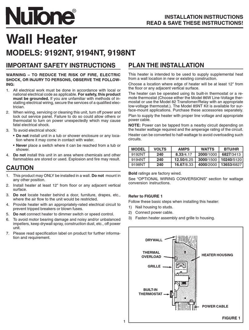
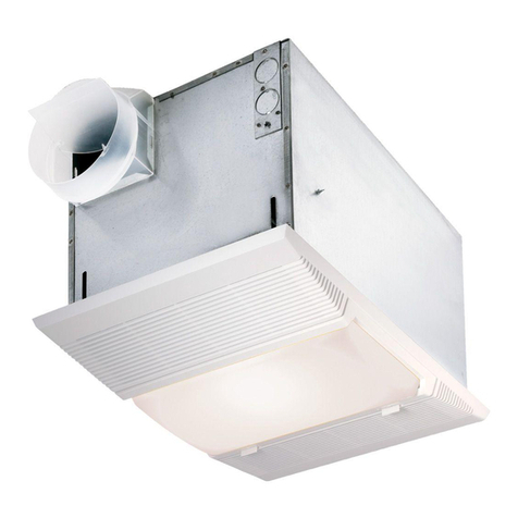
  9. NuTone 665RP User manual

NuTone 665RP User manual

Other manuals for 665RP

3

Other NuTone Heater manuals

NuTone QTXN110HFLT User manual

NuTone

NuTone QTXN110HFLT User manual

NuTone 120 User manual

NuTone

NuTone 120 User manual

NuTone 656 User manual

NuTone

NuTone 656 User manual

NuTone Heat-A-Vent 605RP User manual

NuTone

NuTone Heat-A-Vent 605RP User manual

NuTone 157 User manual

NuTone

NuTone 157 User manual

NuTone 9417DNM User manual

NuTone

NuTone 9417DNM User manual

NuTone 9192NT User manual

NuTone

NuTone 9192NT User manual

NuTone 6200 User manual

NuTone

NuTone 6200 User manual

NuTone QTXN110HL Instruction sheet

NuTone

NuTone QTXN110HL Instruction sheet

NuTone 9412D User manual

NuTone

NuTone 9412D User manual

NuTone 9905-RO2 User manual

NuTone

NuTone 9905-RO2 User manual

NuTone 665RP User manual

NuTone

NuTone 665RP User manual

NuTone 9376N User manual

NuTone

NuTone 9376N User manual

NuTone 9297T User manual

NuTone

NuTone 9297T User manual
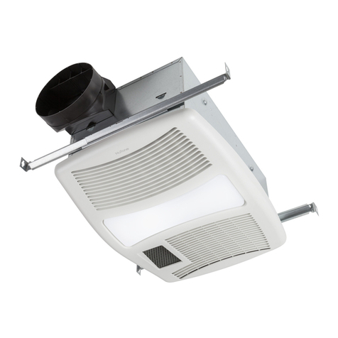
NuTone 154 User manual

NuTone

NuTone 154 User manual

NuTone 192 User manual

NuTone

NuTone 192 User manual

NuTone QTXN110HL User manual

NuTone

NuTone QTXN110HL User manual

NuTone 665RP User manual

NuTone

NuTone 665RP User manual

NuTone 120 User manual

NuTone

NuTone 120 User manual

NuTone 161 User manual

NuTone

NuTone 161 User manual

NuTone 9093WH DELUXE HEAT-A-VENTLITE User manual

NuTone

NuTone 9093WH DELUXE HEAT-A-VENTLITE User manual

NuTone 165F User manual

NuTone

NuTone 165F User manual
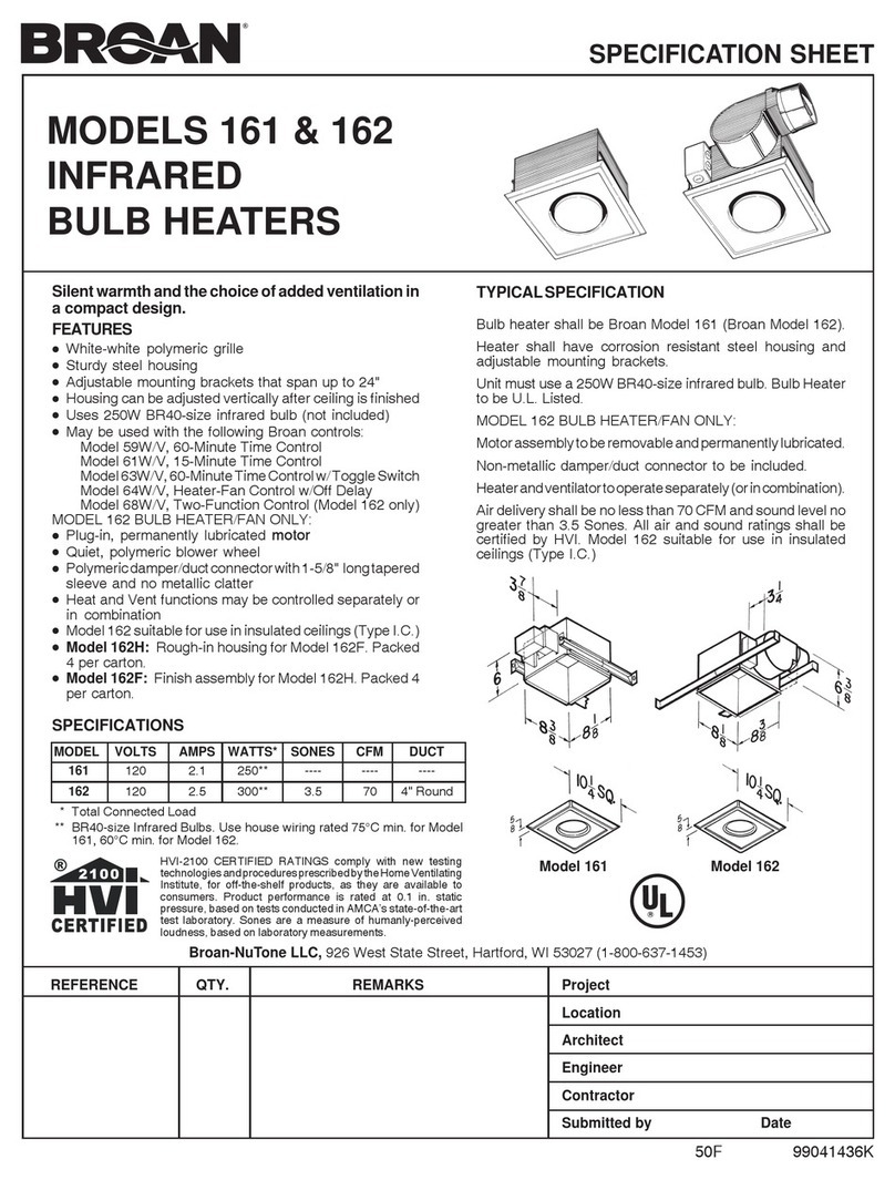
NuTone 6201 User manual

NuTone

NuTone 6201 User manual

NuTone 765H80L User manual

NuTone

NuTone 765H80L User manual

Popular Heater manuals by other brands

Porter-Cable PCXH80KT Operating instructions and owner's manual

Porter-Cable

Porter-Cable PCXH80KT Operating instructions and owner's manual

Dyna-Glo RA18LPDG user manual

Dyna-Glo

Dyna-Glo RA18LPDG user manual

Dimplex PLX050E instruction manual

Dimplex

Dimplex PLX050E instruction manual

EOS Herkules XL S120 installation instructions

EOS

EOS Herkules XL S120 installation instructions

Trebs Comfortheat 99209 manual

Trebs

Trebs Comfortheat 99209 manual

Biddle STYLE2 Series Installation operation & maintenance

Biddle

Biddle STYLE2 Series Installation operation & maintenance

Vermont Castings Non-Catalytic Convection Heater 2477CE Installation and operating manual

Vermont Castings

Vermont Castings Non-Catalytic Convection Heater 2477CE Installation and operating manual

Fagor RA-1505 Instructions for use

Fagor

Fagor RA-1505 Instructions for use

THERMAL FLOW Delta 175 Operating instructions manual

THERMAL FLOW

THERMAL FLOW Delta 175 Operating instructions manual

GET G2CH instructions

GET

GET G2CH instructions

ApenGroup PK Series User, installation, and maintenance manual

ApenGroup

ApenGroup PK Series User, installation, and maintenance manual

oventrop Regucor Series quick start guide

oventrop

oventrop Regucor Series quick start guide

Blaze King CLARITY CL2118.IPI.1 Operation & installation manual

Blaze King

Blaze King CLARITY CL2118.IPI.1 Operation & installation manual

ELMEKO ML 150 Installation and operating manual

ELMEKO

ELMEKO ML 150 Installation and operating manual

BN Thermic 830T instructions

BN Thermic

BN Thermic 830T instructions

KING K Series Installation, operation & maintenance instructions

KING

KING K Series Installation, operation & maintenance instructions

Empire Comfort Systems RH-50-5 Installation instructions and owner's manual

Empire Comfort Systems

Empire Comfort Systems RH-50-5 Installation instructions and owner's manual

Well Straler RC-16B user guide

Well Straler

Well Straler RC-16B user guide

manuals.online logo
manuals.online logoBrands
  • About & Mission
  • Contact us
  • Privacy Policy
  • Terms and Conditions

Copyright 2025 Manuals.Online. All Rights Reserved.

INSTALLATION INSTRUCTIONS
READ & SAVE THESE INSTRUCTIONS!
Heat-A-Ventlite®
Combination
MODEL: 665RP
Type IC suitable for use under thermal insulation
LOCATION
1. Mount heater to ceiling joists, or if necessary, to a header
installed between joists.
2. Caution: Do not mount heater closer than 12" to a
vertical surface. Do not mount over tub or in shower
enclosure.
3. Installation in existing construction requires an accessible
area above the desired location. Make sure that wiring
and ducting can be run to the location.
4.
For installation in sloped ceilings up to 12/12 pitch.
5
.
Ductwork must point up.
FIGURE 1
MOUNTING HEATER HOUSING
NEW CONSTRUCTION
Using Hanger Bars
Refer to Figure 1.
1. Insert hanger bars in slots provided in housing.
2. Locate heater housing between joists so that bottom of heater housing is even with the planned finished ceiling.
3. Use screws or nails (not provided) to secure hanger bars to ceiling joists.
Using Side Mounting Tabs
1. Locate heater housing next to ceiling joist.
2. Use wood screws (not provided) through keyhole slots in mounting tabs to loosely attach housing to ceiling joist.
3. Adjust housing so that it will be flush with the finished ceiling. When housing is properly adjusted, tighten screw in slots to
secure housing.
EXISTING CONSTRUCTION
1. Determine desired location for heater.
2. Drill a small hole through the ceiling at the desired location and stick a coat hanger or stiff wire through hole into attic to
help find the location from above.
3. Check the area above to make sure that wiring and ducting can be installed and that the installation will not interfere with
existing electrical wiring.
4. From above, place the housing between ceiling joists at the desired location. Using the housing as a template, mark the
area to be cut out along the bottom flange of the housing.
5. After making the cutout, install the housing in the opening using the hanger bars or mounting tabs as described above.
Make sure that the bottom of the housing is flush with the bottom of the finished ceiling.
To register this product, visit www.nutone.com
FIGURE 3 FIGURE 4
HEATER JUNCT ION BOX
LIGHT
RECEPTACLE
WHIT E
WHITE
RED
GREEN
WAL L SW I T CH B O X
WHI T E
BLACK
120VAC L INE
SUPPLY
GROUND
LIGHT
HEAT
VENT
WHI T E
BLACK
B LUE
VE NT
RECEPTAC LE
HEAT
RECEPTAC LE
(W HIT E )
FIGURE 2
D U C T I N G
1. Snap plastic duct adapter and damper assembly over
flanged opening on housing. Connect 4" round duct to the
duct adapter and secure with duct tape. The duct should
be run to the outside of the structure through a roof or wall
cap. For maximum performance keep duct runs as short
and as straight as possible.
N O T E : This heater is provided with Self-Hold resetable
thermal protector. If the heater shuts off during operation, turn
to off at the wall switch and wait approximately 15 minutes
before turning back on. If heater does not reset or trips
repeatedly, contact a NuTone service center.
WIRING
All wiring must comply with local and national codes
and unit must be properly grounded.
1. Run 120VAC, 60 Hz supply wiring to the wall switch (not
provided) The unit must be wired on a separate 20
Amp circuit.
2. Run wiring from the switch to the housing junction box.
Loosen screw holding exterior wiring compartment cover
and remove cover. Interior wiring compartment cover
can be removed if necessary by loosening screw through
key hole slot in cover. Remove knockout(s) as required
and install approved box connectors.
3. Refer to Figure 2. Connect white wires in junction box to
white (neutral) supply wire. Connect the blue wire in the
junction box to the supply wire from the vent switch.
Connect the black wire to the supply wire from the light
switch. Connect the red wire in the junction box to the
supply wire from the heat switch. Connect green ground
leads in the junction box to the supply ground.
4. Replace wiring compartment cover and tighten screw to
secure.
5. Insert vent motor plug in vent receptacle on interior
wiring compartment cover. Insert plug from heater
assembly into the heater receptacle on the interior wiring
compartment cover.
REFLECTOR
REFLECTOR
MOUNTING
SCREW
LIGHT SOCKET
LENS
MOUNTING THE REFLECTOR AND
G R I L L E
1. Refer to Figure 3. Place the reflector in the opening in the
center of the grille. The notches in the reflector should fit
over the pegs on either side of the opening. Insert plug
from lamp socket into lamp receptacle on wiring
c o m p a r t m e n t .
2. Place 1" screw, provided, through the center hole in the
reflector and thread it into the hole in the mounting bracket
running across the housing. Tighten the screw just enough
to hold the grille firmly against the ceiling.
3. Install a 100 watt maximum, type A-19 light bulb.
4. Refer to Figure 4. Snap lens into position in center of
grille. To remove the lens for relamping, gently pry along
the side of the lens with a screwdriver to disengage the
snap in tabs while pulling down on the lens.
Product specifications subject to change without notice.
4820 Red Bank Road, Cincinnati, Ohio 45227
Printed in Canada, Rev. 02/06, Part No. 101001
HEATER
PRODUCT
GROUP
665RP
MODEL NUMBER
Rev.
FEBRUARY
2006
EFFECTIVE
DATE
1
2
4
3
7
8
9
10
16
17
5
14
13
12
15
PA RTS LIST
NOTE: Always order by
current part number
NuTone
Attn: Parts Department
4820 Red Bank Road
Cincinnati, OH 45227-1599
Phone: (513) 527-5426
Fax: (513) 527-5173
VENT ASSEMBLYHEATER ASSEMBLY
611
18
19
CURRENT
ORIGINAL REPLACEMENT
REF. PART NO. PART DESCRIPTION PART NO.
1 44388 Hanger Bar 44388-000
2 88552 Outlet Box Cover 88552-000
3 66204 Receptacle-Light 66204-000
4 56721 Receptacle-Heat 56721-000
5 57976 Receptacle-Vent 57976-000
6 100976 Heater Assembly 100976-000
7 61579 Heat Scroll 61579-000
8 88569 Motor-Heat 88569-000
9 66583 Blower Wheel-Heat 66583-000
10 100978 Heater Element 0969B-000
11 89849 Vent Assembly 89849-000
12 61449 Vent Scroll 61449-000
13 89850 Motor-Vent 89850-000
14 68739 Blower Wheel-Vent 82403-000
15 30652 Duct Adapter 30652-000
16 89760 Grille 89760-000
17 53740 Lens 53740-000
18 89765 Reflector 89765-000
19 35758 Lamp Socket 35758-000
665RP I.I.