Nuvation Energy BMS User manual

Nuvation Energy Low-Voltage BMS
Installation Guide
2019-08-27

Table of Contents
Important Safety Information . . . . . . . . . . . . . . . . . . . . . . . . . . . . . . . . . . . . . . . . . . . . . . . . . . Ê1
1. Introduction . . . . . . . . . . . . . . . . . . . . . . . . . . . . . . . . . . . . . . . . . . . . . . . . . . . . . . . . . . . . Ê2
1.1. About this Guide . . . . . . . . . . . . . . . . . . . . . . . . . . . . . . . . . . . . . . . . . . . . . . . . . . . . . . Ê2
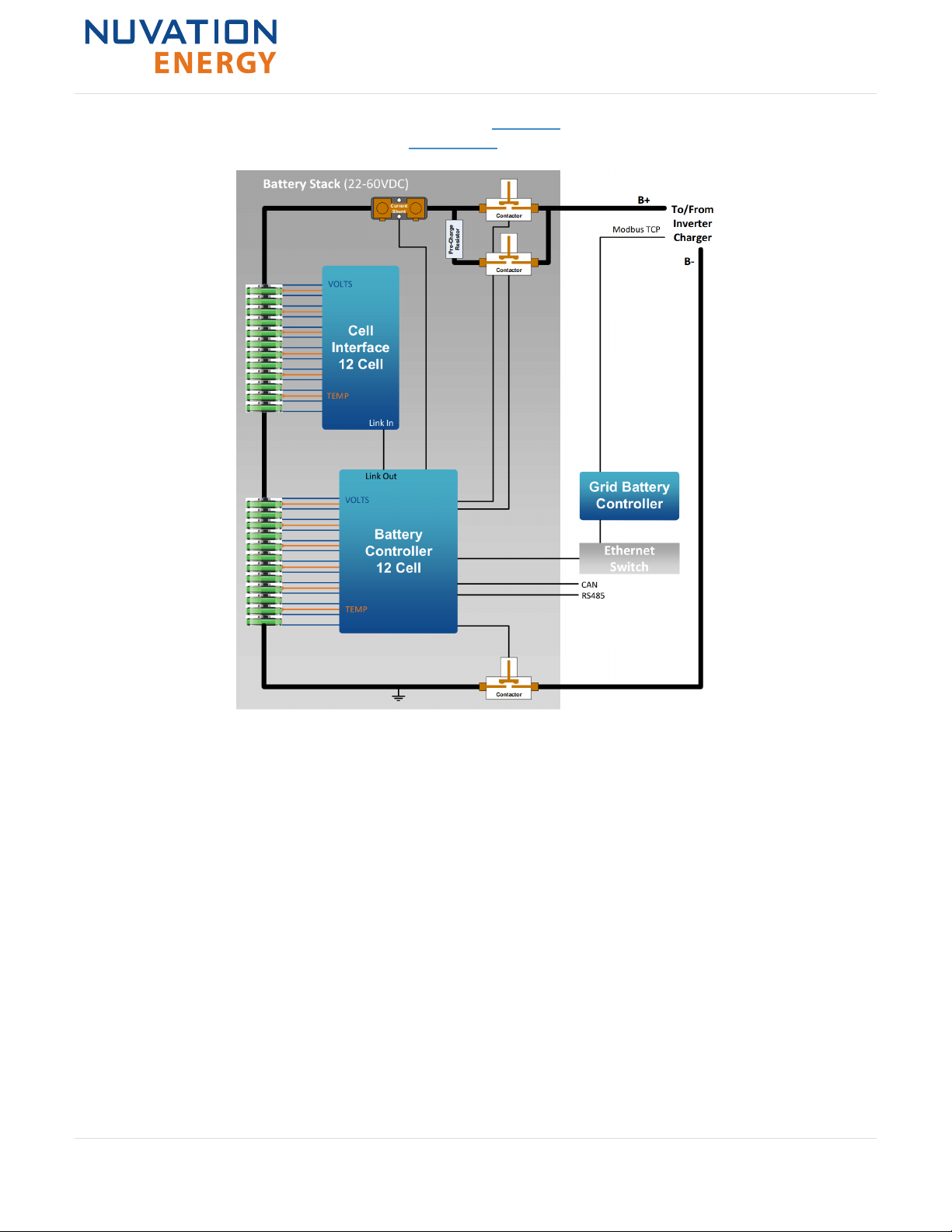
2. System Overview . . . . . . . . . . . . . . . . . . . . . . . . . . . . . . . . . . . . . . . . . . . . . . . . . . . . . . . . Ê3
3. Battery Controller . . . . . . . . . . . . . . . . . . . . . . . . . . . . . . . . . . . . . . . . . . . . . . . . . . . . . . . . Ê5
3.1. Overview . . . . . . . . . . . . . . . . . . . . . . . . . . . . . . . . . . . . . . . . . . . . . . . . . . . . . . . . . . . Ê5
3.2. GPIO Block . . . . . . . . . . . . . . . . . . . . . . . . . . . . . . . . . . . . . . . . . . . . . . . . . . . . . . . . . . Ê5
3.3. CAN Bus and RS485 / Modbus RTU Block . . . . . . . . . . . . . . . . . . . . . . . . . . . . . . . . . . . . . Ê6
3.4. Power Supply, Current Shunt, and Contactor Drivers . . . . . . . . . . . . . . . . . . . . . . . . . . . . . Ê6
3.5. Mechanical Dimensions . . . . . . . . . . . . . . . . . . . . . . . . . . . . . . . . . . . . . . . . . . . . . . . . . Ê6
3.6. Electric Connections. . . . . . . . . . . . . . . . . . . . . . . . . . . . . . . . . . . . . . . . . . . . . . . . . . . . Ê7
3.6.1. Overview . . . . . . . . . . . . . . . . . . . . . . . . . . . . . . . . . . . . . . . . . . . . . . . . . . . . . . . . Ê7
3.6.2. J1: Link Out . . . . . . . . . . . . . . . . . . . . . . . . . . . . . . . . . . . . . . . . . . . . . . . . . . . . . . Ê7
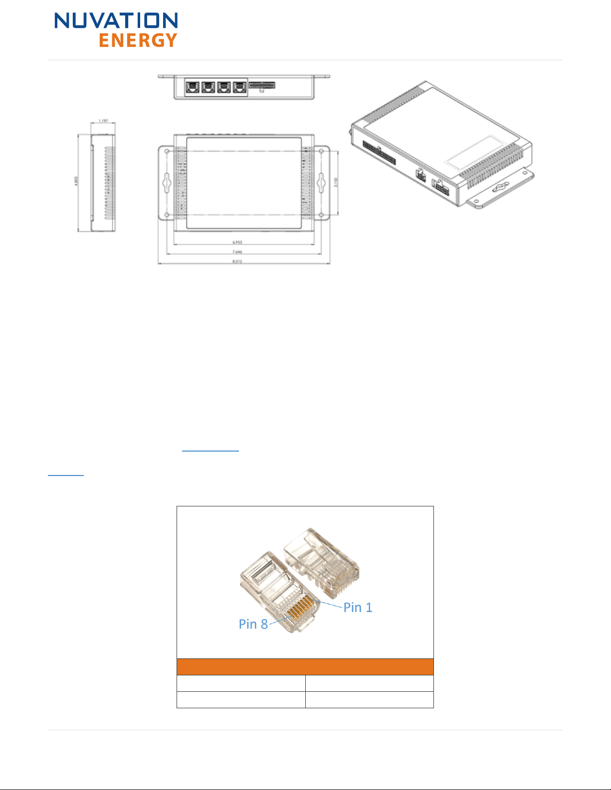
3.6.3. J2: Ethernet / Modbus TCP . . . . . . . . . . . . . . . . . . . . . . . . . . . . . . . . . . . . . . . . . . . . Ê8
3.6.4. J3: CAN . . . . . . . . . . . . . . . . . . . . . . . . . . . . . . . . . . . . . . . . . . . . . . . . . . . . . . . . . Ê8
3.6.5. J4: RS485 / Modbus RTU . . . . . . . . . . . . . . . . . . . . . . . . . . . . . . . . . . . . . . . . . . . . . Ê9
3.6.6. J5: Control / GPIO. . . . . . . . . . . . . . . . . . . . . . . . . . . . . . . . . . . . . . . . . . . . . . . . . . Ê9
3.6.7. J6: Contactors / -V Power. . . . . . . . . . . . . . . . . . . . . . . . . . . . . . . . . . . . . . . . . . . . Ê11
3.6.8. J7: Current Shunt / +V Power. . . . . . . . . . . . . . . . . . . . . . . . . . . . . . . . . . . . . . . . . Ê15
3.6.9. J8: Cell Voltage / Temperature . . . . . . . . . . . . . . . . . . . . . . . . . . . . . . . . . . . . . . . . Ê17
3.7. Grounding and Fusing . . . . . . . . . . . . . . . . . . . . . . . . . . . . . . . . . . . . . . . . . . . . . . . . . Ê27
4. Cell Interface Expansion Module . . . . . . . . . . . . . . . . . . . . . . . . . . . . . . . . . . . . . . . . . . . . . Ê31
4.1. Scaling to over 16 channels . . . . . . . . . . . . . . . . . . . . . . . . . . . . . . . . . . . . . . . . . . . . . Ê31
4.1.1. Safety Considerations . . . . . . . . . . . . . . . . . . . . . . . . . . . . . . . . . . . . . . . . . . . . . . Ê32
4.2. Mechanical Overview . . . . . . . . . . . . . . . . . . . . . . . . . . . . . . . . . . . . . . . . . . . . . . . . . . Ê32
4.2.1. Optional DIN rail mounting Kit . . . . . . . . . . . . . . . . . . . . . . . . . . . . . . . . . . . . . . . . Ê33
4.3. Electrical Connections . . . . . . . . . . . . . . . . . . . . . . . . . . . . . . . . . . . . . . . . . . . . . . . . . Ê35
4.3.1. Link Out . . . . . . . . . . . . . . . . . . . . . . . . . . . . . . . . . . . . . . . . . . . . . . . . . . . . . . . . Ê35
4.3.2. Link In . . . . . . . . . . . . . . . . . . . . . . . . . . . . . . . . . . . . . . . . . . . . . . . . . . . . . . . . . Ê35
4.3.3. Battery Cells . . . . . . . . . . . . . . . . . . . . . . . . . . . . . . . . . . . . . . . . . . . . . . . . . . . . . Ê37
4.3.4. Temperature Sensors . . . . . . . . . . . . . . . . . . . . . . . . . . . . . . . . . . . . . . . . . . . . . . . Ê43
5. Software Configuration . . . . . . . . . . . . . . . . . . . . . . . . . . . . . . . . . . . . . . . . . . . . . . . . . . . . Ê46
5.1. Enabling Battery Controller expansion with Cell Interface module . . . . . . . . . . . . . . . . . . . Ê46

Important Safety Information
The content in this document must be followed in order to ensure safe operation of Nuvation
Energy BMS.
Do NOT connect the J7: Current Shunt / +V Power connector to the Battery
Controller until all other connections have been made.
Properly insulate or remove any unused wires. Unused wires can couple
excessive system noise into Nuvation Energy BMS which can disrupt
communication and lead to undesirable behaviors.
Please be aware of high voltages present in your system and follow all
necessary safety precautions.
The provided module enclosures are not fire enclosures.
Depending on battery chemistry, there might be a nominal voltage per cell
which adds up in series and is always present. There are many different
battery chemistries with different current capacities, and so high voltage with
high current capacity may be present while connecting the Nuvation Energy
BMS. You must use proper electrical safety precautions when handling any part
of the Nuvation Energy BMS.
Neither Nuvation Energy or any of its employees shall be liable for any direct,
indirect, incidental, special, exemplary, personal or consequential harm or
damages (including, but not limited to, procurement or substitute goods or
services; loss of use, data, or profits; or business interruption) however caused
and on any theory of liability, whether in contract, strict liability, or tort
(including negligence or otherwise) arising in any way out of the use of this
product.
The Nuvation Energy BMS relies on your system charger to charge the battery
cells; do not leave your charger off while the Nuvation Energy BMS is powered
from the stack for prolonged periods of time. The Nuvation Energy BMS should
be shut down when the system is in storage to minimize the drain on the cells.
Nuvation Energy Low-Voltage BMS - Installation Guide
© 2019 Nuvation Energy 12019-08-27

1. Introduction
Thank you for choosing Nuvation Energy BMS
Low-Voltage Battery Controller is an enterprise-grade battery management system with features that
extend battery life, ensuring battery safety, and cell balancing.
You can take advantage of the highly configurable browser-based user interface and custom-tune
Low-Voltage Battery Controller to your specific target application.
1.1. About this Guide
This Nuvation Energy Low-Voltage BMS: Installation Guide provides wiring instructions to connect
your Low-Voltage Battery Controller to your system.
Once you have successfully completed the installation process, please follow instructions in the
Operator Interface Manual for accessing and configuring the Nuvation Energy BMS Operator Interface
for the Battery Controller.
We thrive on your feedback and what we build is driven by your input. Please submit support
tickets to support@nuvationenergy.com.
Nuvation Energy Low-Voltage BMS - Installation Guide
© 2019 Nuvation Energy 22019-08-27

2. System Overview
The Nuvation Energy Low-Voltage BMS is a complete battery management system that provides cell
balancing and charge management for virtually any battery chemistry using a Battery Controller. The
Battery Controller is designed for input voltage of 11-60 V DC. It can manage up to 12 or 16 battery
cells in series, and can be expanded to manage additional cells with a Nuvation Energy Cell Interface
module.
An example 12 or 16 channel configuration is shown in Figure 1. This configuration requires a single
Battery Controller.
Figure 1. Nuvation Energy Low-Voltage BMS System Overview
Nuvation Energy Low-Voltage BMS - Installation Guide
© 2019 Nuvation Energy 32019-08-27

An example 24-channel configuration is shown in Figure 2. This configuration requires a Battery
Controller and a Cell Interface. Please see Section 4.1 for more details.
Figure 2. Low-Voltage BMS System Overview: 24-channel Application
Nuvation Energy Low-Voltage BMS - Installation Guide
© 2019 Nuvation Energy 42019-08-27

3. Battery Controller
3.1. Overview
Low-Voltage Battery Controller module safely manages up to 12 or 16 cells by measuring cell voltage,
temperature and current and applying software decision-making to control contactors, communicate
with energy storage controllers, and interface with general purpose I/O.
The Battery Controller is able to operate as a stand-alone battery management system, requiring no
additional Nuvation Energy BMS modules to manage a stack of up to 12 or 16 cells. Nuvation Energy
Cell Interface may be used to increase the stack size in systems that are rated less than 60 V DC.
The Battery Controller is available in two models:
•The NUV300-BC-12 which can monitor up to 12 series-connected cells
•The NUV300-BC-16 which can monitor up to 16 series-connected cells
3.2. GPIO Block
The GPIO and control inputs are accessible at the J5: Control / GPIO connector.
The general-purpose outputs from the Battery Controller are implemented using optical MOSFET
switches. These outputs are non-polarized, presenting an on-resistance of typically 2 Ω and capable
of carrying 400 mA of DC or RMS current when activated. Figure 3 shows a high level circuit diagram
for the GPO pins.
GPO_ISOx_B
60V DC Isolation
GPO_ISOx_A
Logic GPO
x4
GPIO
Figure 3. GPIO Circuit Diagram
The general-purpose and specific-purpose (FAULT_CLEAR, FACTORY_RESET, SHUTDOWN) inputs to the Battery
Controller are implemented using optical isolation components. The current source for these inputs is
provided in the Battery Controller and each input is activated by providing a simple contact closure to
the common point.
The BMS Enable input differs slightly from the other specific-purpose inputs. This control requires a
contact closure between the BMS_ENABLE# and VBOT signals and must not be referenced to the common
point of the other inputs. It is used to start the Battery Controller after it has been shut down due to
Nuvation Energy Low-Voltage BMS - Installation Guide
© 2019 Nuvation Energy 52019-08-27

activation of the SHUTDOWN input, low battery, or some other condition invoked under software control.
BMS_ENABLE# is pulled up to the battery stack positive (potentially 60 V away from VBOT) so the
switch/external controller must be tolerant of the maximum battery stack voltage.
3.3. CAN Bus and RS485 / Modbus RTU Block
The CAN Bus communication channel is available on the J3: CAN connector. The RS485 / Modbus RTU
communication channel is available on the J4: RS485 / Modbus RTU connector.
These communication channels are isolated from the battery stack and share their common reference
with each other, with the general-purpose I/O, and with the specialized control inputs. A 120 Ω bus
termination is required on each end of the bus for these communication channels. Termination is not
provided within the Battery Controller on stock production units.
3.4. Power Supply, Current Shunt, and Contactor Drivers
Operating power, including primary power source for operating the contactor coils, is connected to the
Battery Controller at two connectors: positive to the J7: Current Shunt / +V Power connector, and
negative to the J6: Contactors / -V Power connector.
The current shunt, which is connected in series with the battery stack at the positive end, connects its
sense points to the Battery Controller at the J7: Current Shunt / +V Power connector.
Up to 4 system contactors may be connected and controlled by the Battery Controller, connecting to
the Battery Controller at the J6: Contactors / -V Power connector.
3.5. Mechanical Dimensions
The overall dimensions of the Battery Controller are 220 mm X 125 mm X 30 mm. Extra space should
be provided around the module to allow for easy installation/maintenance.
Dimensions in the diagram below are shown in inches
The Battery Controller should be securely mounted in a vertical orientation, in an environment that
permits free movement of air through all ventilation slots for convection cooling. The Cell Connections
connector (J1) should be facing up or to the left. If it is to be used with a battery chemistry such as
lead-acid, which does not require balancing, the Battery Controller may be mounted horizontally, with
the ventilation slots oriented upwards. It is not advisable to mount the Battery Controller on the
underside of a horizontal surface.
The Low-Voltage Battery Controller weighs approximately 400 g.
Nuvation Energy Low-Voltage BMS - Installation Guide
© 2019 Nuvation Energy 62019-08-27

Figure 4. Mechanical Drawing of Battery Controller
3.6. Electric Connections
3.6.1. Overview
The Battery Controller module has eight connectors. Each connector is described in the following
sections in detail.
3.6.2. J1: Link Out
In certain situations, it may be required to monitor more than 16 cells in series, such as with 2V lead-
acid cells. This connector is used to connect to an additional Cell Interface module to manage more
cells and thermistors. See Section 4.1 for installation instructions for the Cell Interface.
Table 1 describes a typical compatible plug for the J1: Link Out jack.
Table 1. RJ-45 Plug Details
Conec 391J00039X
Manufacturer Conec
Housing 391J00039X
Nuvation Energy Low-Voltage BMS - Installation Guide
© 2019 Nuvation Energy 72019-08-27

Housing material Polycarbonate UL94V-0
Circuits 8
Crimp terminal insulation displacement
Wire gauge range AWG24-26 stranded or
solid
The Link Out interface connector is a standard RJ45 Cat5e rated jack. This interface is used to connect
the Battery Controller module to an expansion Cell Interface module to provide monitoring for
additional battery cells and thermistors.
Table 2. Link Out Connector Pin Assignment
Pin Connection Description Connected to Device
1 No Connect Not Connected No Connect
2 No Connect Not Connected No Connect
3 No Connect Not Connected No Connect
4 No Connect Not Connected No Connect
5 No Connect Not Connected No Connect
6 No Connect Not Connected No Connect
7 LINKBUS_N Link Bus differential pair negative Cell Interface
8 LINKBUS_P Link Bus differential pair positive Cell Interface
3.6.3. J2: Ethernet / Modbus TCP
The Ethernet / Modbus TCP jack is a standard RJ45 Cat5e rated jack. This interface is used as the
primary means of connecting an external system to the Battery Controller to configure the operating
parameters, observe the status, and perform maintenance such as firmware upgrades.
Table 1 describes a typical compatible plug for the J2: Ethernet / Modbus TCP jack.
Table 3. Ethernet / Modbus TCP Connector Pin Assignment
Pin Connection Description Connected to Device
1 TD_P Transmit differential pair positive External Equipment
2 TD_N Transmit differential pair negative External Equipment
3 RD_P Receive differential pair positive External Equipment
4 NUL45 Unused; connected to Pin 5 and terminated External Equipment
5 NUL45 Unused; connected to Pin 4 and terminated External Equipment
6 RD_N Receive differential pair negative External Equipment
7 NUL78 Unused; connected to Pin 8 and terminated External Equipment
8 NUL78 Unused; connected to Pin 7 and terminated External Equipment
3.6.4. J3: CAN
The CANBus 2.0 connector is a standard RJ45 Cat5e rated jack. This interface provides an isolated
Nuvation Energy Low-Voltage BMS - Installation Guide
© 2019 Nuvation Energy 82019-08-27

CANBus 2.0 port.
CANBus termination is not provided within the Battery Controller on stock production units. Standard
120 Ω termination must be installed at each end of the CANBus network.
Table 1 describes a typical compatible plug for the J3: CAN jack.
Table 4. CANBus RJ45 Connector Pin Assignment
Pin Connection Description Connected to Device
1 CAN_P CAN bus differential pair positive External Equipment
2 CAN_N CAN bus differential pair negative External Equipment
3 COMIO Common reference shared with GPIO External Equipment
4 No Connect Not Connected No Connect
5 No Connect Not Connected No Connect
6 No Connect Not Connected No Connect
7 COMIO Common reference shared with GPIO External Equipment
8 No Connect Not Connected No Connect
3.6.5. J4: RS485 / Modbus RTU
The RS-485 connector is a standard RJ45 Cat5e rated jack. This interface provides an isolated RS-485
(Modbus-RTU) port.
RS485 termination is not provided within the Battery Controller on stock production units. Standard
120 Ω termination must be installed at each end of the Modbus-RTU network.
Table 1 describes a typical compatible plug for the J4: RS485 / Modbus RTU jack.
Table 5. RS485 / Modbus RJ45 Connector Pin Assignment
Pin Connection Description Connected to Device
1 No Connect Not Connected No Connect
2 No Connect Not Connected No Connect
3 No Connect Not Connected No Connect
4 MODBUS_P MODBUS differential pair positive External Equipment
5 MODBUS_N MODBUS differential pair negative External Equipment
6 No Connect Not Connected No Connect
7 No Connect Not Connected No Connect
8 COMIO Common reference shared with GPIO External Equipment
3.6.6. J5: Control / GPIO
Table 6 describes the recommended plug and crimp terminals to be used with the J5: Control / GPIO
connector.
Table 6. J5: Control / GPIO plug housing and terminal details
Nuvation Energy Low-Voltage BMS - Installation Guide
© 2019 Nuvation Energy 92019-08-27

Samtec IPD1-12-D
Manufacturer Samtec Inc
Housing IPD1-12-D
Housing material Nylon (Zytel® PA66) UL94V-2
Circuits 24
Crimp terminal CC79R-2024-01-L
Wire gauge range AWG20-24 stranded
This interface provides connections to isolated general purpose inputs and outputs, and also specific
function inputs that can be used to:
•Enable the power supply
•Invoke or force a system shutdown
•Clear system faults
•Invoke a factory reset
The functionalities of the general purpose inputs and outputs are configured by the end-user to match
their needs.
Table 7. GPI, GPO, and Special Function Connector Pin Assignment
Pin Connection Description Connected to Device
1 GPO_ISO0_A Digital Output 0 External Equipment
2 GPO_ISO1_A Digital Output 1 External Equipment
3 GPO_ISO2_A Digital Output 2 External Equipment
4 GPO_ISO3_A Digital Output 3 External Equipment
5 +5V_GPIO_ISO Isolated +5V I/O Power Supply External Equipment
6 GPI_ISO0_K Input detector 0 External Equipment
7 GPI_ISO1_K Input detector 1 External Equipment
8 GPI_ISO2_K Input detector 2 External Equipment
9 GPI_ISO3_K Input detector 3 External Equipment
10 FAULT_CLEAR# Momentary to COMIO to clear faults Processor GPI via logic elements
Nuvation Energy Low-Voltage BMS - Installation Guide
© 2019 Nuvation Energy 10 2019-08-27

Pin Connection Description Connected to Device
11 FACTORY_RESET# Hold to COMIO during startup to perform a
factory reset
Processor GPI via logic elements
12 BMS_ENABLE# Momentary to VBOT to enable BMS; Hold to
VBOT to defeat Shutdown
Power supply enable gate
NOTE: different reference from other inputs
13 GPO_ISO0_B Digital Output 0 External Equipment
14 GPO_ISO1_B Digital Output 1 External Equipment
15 GPO_ISO2_B Digital Output 2 External Equipment
16 GPO_ISO3_B Digital Output 3 External Equipment
17 COMIO Isolated I/O Power Supply Common
Reference
External Equipment
18 COMIO Isolated I/O Power Supply Common
Reference
External Equipment
19 COMIO Isolated I/O Power Supply Common
Reference
External Equipment
20 COMIO Isolated I/O Power Supply Common
Reference
External Equipment
21 COMIO Isolated I/O Power Supply Common
Reference
External Equipment
22 COMIO Isolated I/O Power Supply Common
Reference
External Equipment
23 SHUTDOWN# Momentary to COMIO to invoke shutdown;
Hold to COMIO to force shutdown
Processor GPI via logic
elements, hard shutdown (no
software) via logic elements with
longer press
24 VBOT VBOT
3.6.7. J6: Contactors / -V Power
Table 8 describes the recommended plug and crimp terminals to be used with the J6: Contactors / -V
Power connector.
Table 8. J6: Contactors / -V Power plug housing and terminal details
Nuvation Energy Low-Voltage BMS - Installation Guide
© 2019 Nuvation Energy 11 2019-08-27

Molex 39-01-2125
Manufacturer Molex Incorporated
Housing 39-01-2125
Housing material Nylon UL94V-0
Circuits 12
Crimp terminal 39-00-0073
Wire gauge range AWG18-24 stranded
This interface is used to drive up to 4 external contactor coils and to select their power source. The
negative operating power is provided in a fused connection to this connector (fuses not provided).
Connecting to Contactor Coils
The Battery Controller provides coil drivers for contactor coils up to 24 V DC. The internal 24 V power
supply of the Battery Controller may be used to power the coils if the following conditions are
satisfied:
•24 V coils are connected
•The worst-case coil inrush current is below 1.5 A
•The sum of all connected coil currents is less than 1 A
To use the internal power supply, connect together pins 11 (+VCOIL) and 12 (+24V) of J6 to deliver +24
V to the +VCOIL input. Pin 5 (VCOIL_RETURN) is left disconnected and should be insulated to prevent shorts.
Other coil voltages in the 12V-24 V range and total currents of up to 1.5 A per coil may be supported
through the use of an external DC power source. Such a supply must be connected between +VCOIL
(pin 11) and VCOIL_RETURN (pin 5) of J6.
As depicted in Figure 14, if an external power supply is used to power the Battery Controller instead
of the battery stack, the VCOIL_RETURN (pin 5) connection of J6 must be externally connected to the
bottom of the battery stack. If using a dedicated external power supply to power the contactor coils,
connect the common return of that supply to this pin.
Coil back-EMF protection is provided by the Battery Controller that clamps at 40 V. External clamping
diodes of lower voltages may be connected if required.
The bottom of the attached battery stack is internally connected to the common
return path for all contactor coils (pins 1~5 of J6). It is recommended that no ground
connection be made at the coils to avoid creating an inadvertent ground fault or
ground loop.
Contactor coils are to be connected between the COILn_HI and COM pins of J6 as required. When the
Battery Controller activates a contactor, the COILn_HI output is driven to a VCOIL voltage level.
Unused contactor coil wires should be properly insulated or removed. Refer to Figure 13 and Figure
14 for use of the –VPOWER connection at J6.
Contactor coils, internal and external supply connections to J6 are shown in Figure 5 and Figure 6.
Nuvation Energy Low-Voltage BMS - Installation Guide
© 2019 Nuvation Energy 12 2019-08-27

Figure 5. Connection to J6: Two 24V contactor coils powered from internal supply
Nuvation Energy Low-Voltage BMS - Installation Guide
© 2019 Nuvation Energy 13 2019-08-27

Figure 6. Connection to J6: Four contactor coils powered from external supply
Table 9. Stack Power Return and Contactors Connector Pin Assignment
Pin Connection Description Connected to Device
1 COM Negative Coil 1 Contactor 1 negative coil
connection
2 COM Negative Coil 2 Contactor 2 negative coil
connection
3 COM Negative Coil 3 Contactor 3 negative coil
connection
4 COM Negative Coil 4 Contactor 4 negative coil
connection
Nuvation Energy Low-Voltage BMS - Installation Guide
© 2019 Nuvation Energy 14 2019-08-27

Pin Connection Description Connected to Device
5 VCOIL_RETURN Negative reference for external supply External Power Supply. Refer to
Figure 13 and Figure 14 for
additional requirements
6 -VPOWER Power return of Battery Controller Bottom of Stack
7 COIL1_HI Positive Coil 1 Contactor 1 positive coil
connection
8 COIL2_HI Positive Coil 2 Contactor 2 positive coil
connection
9 COIL3_HI Positive Coil 3 Contactor 3 positive coil
connection
10 COIL4_HI Positive Coil 4 Contactor 4 positive coil
connection
11 +VCOIL 12~24V Contactor Coil Power Supply Connect to external power
supply, or to pin 12 if driving
contactor coil from internal
power supply
12 +24V Internal Power Supply Connect to pin 11 if driving
contactor coils from internal
power supply
3.6.8. J7: Current Shunt / +V Power
Table 10 describes the recommended plug and crimp terminals to be used with the J7: Current Shunt /
+V Power connector.
Table 10. J7: Current Shunt / -V Power plug housing and terminal details
Molex 39-01-2065
Manufacturer Molex Incorporated
Housing 39-01-2065
Housing material Nylon UL94V-0
Circuits 6
Nuvation Energy Low-Voltage BMS - Installation Guide
© 2019 Nuvation Energy 15 2019-08-27

Crimp terminal 39-00-0073
Wire gauge range AWG18-24 stranded
This interface is used to connect the current shunt to the Battery Controller. The positive operating
power is provided in a fused connection to this connector (fuses not provided).
This connection must only be made after all other connections to the Battery
Controller have been made.
Connecting to a Current Shunt
The Battery Controller requires the shunt to be on the high side (positive end) of the battery stack.
The VSHUNT_REF signal is used to compensate for the voltage drop in the sense wires as well as to
provide the positive reference for measuring the overall voltage of the stack. VSHUNT_BAT and VSHUNT_LOAD
carry the differential voltage measurement from the shunt. VSHUNT_BAT must be closest to the battery
cells and VSHUNT_LOAD must be closest to the Stack Fuse so that the measured current has the correct
polarity. To minimize outside interference, twist VSHUNT_LOAD and VSHUNT_BAT together to form a twisted
pair, then run all 3 wires close together.
Figure 7. Current shunt and Power fuse connection to J7
Nuvation Energy Low-Voltage BMS - Installation Guide
© 2019 Nuvation Energy 16 2019-08-27

Table 11. Current Shunt Connector Pin Assignment
Pin Connection Description Connected to Device
1 +VPOWER Main power supply input Positive end of the stack or
other power source
2 No Connect Not Connected No Connect
3 No Connect Not Connected No Connect
4 VSHUNT_LOAD Differential voltage input; Load side Load side of current shunt
5 VSHUNT_BAT Differential voltage input; Battery side Battery side of current shunt
6 VSHUNT_REF Voltage reference for voltage measurement Battery side of current shunt
3.6.9. J8: Cell Voltage / Temperature
This interface is used to connect the battery cell voltage sense wires as well as up to eight 10 kΩ NTC
thermistors to the Battery Controller module.
Table 12. J8: Cell Voltage / Temperature plug housing and terminal details
Samtec IPD1-20-D
Manufacturer Samtec Inc
Housing IPD1-20-D
Housing material Nylon (Zytel® PA66) UL94V-2
Circuits 40
Crimp terminal CC79R-2024-01-L
Wire gauge range AWG20-24 stranded
Battery Cell Connections
The following two models of the Battery Controller are available, supporting a variety of cell counts
and voltage ranges:
NUV300-BC-12: Connected cells are monitored internally by a single functional block. This
functional block requires a minimum stack voltage of 11 V to operate and measure its input voltages.
The total voltage across the stack can be up to 60 V. Unused cell tap wires should be connected to the
last cell in the stack. See Figure 8 and Figure 9 for examples of how to connect cells to the NUV300-
BC-12.
NUV300-BC-16: Connected cells are monitored internally by two functional blocks, each measuring
Nuvation Energy Low-Voltage BMS - Installation Guide
© 2019 Nuvation Energy 17 2019-08-27

eight cells (C0 to C8 and C8 to C16). Each functional block requires a minimum of 11 V across it to
operate and measure its input voltages. The total voltage across the stack can be up to 60 V. See
Figure 10, Figure 11 and Figure 12 for examples of how to connect cells to the NUV300-BC-12.
Groups do not need to contain the same number of cells but the maximum and minimum voltage
limits must be met, as stated in Table 13.
Table 13. Battery Controller supported cell connections
Battery Controller Cell groups Max cell
inputs per
group
Max cell
voltage per
input
Max total
voltage
across
group
Max total
voltage
across all
groups
Min voltage
per group
NUV300-BC-12 1 12 5V 60V 60V 11V
NUV300-BC-16 2 8 5V 40V 60V 11V
The same style of connector is used for cell voltage and temperature sensor connection in both the
NUV300-BC-12 and NUV300-BC-16. The names of the pins for the J8 connector are given in Table 14.
Table 14. Battery Cell Voltage and Temperature Probes connector pin assignment
Pin Connection Description Connected to Device
1 TPROBE1 External Temperature Probe Input 1 10 kΩ NTC Thermistor
2 VBOT_TEMP External Temperature Probe Reference 1 10 kΩ NTC Thermistor
3 TPROBE2 External Temperature Probe Input 2 10 kΩ NTC Thermistor
4 VBOT_TEMP External Temperature Probe Reference 2 10 kΩ NTC Thermistor
5 TPROBE3 External Temperature Probe Input 3 10 kΩ NTC Thermistor
6 VBOT_TEMP External Temperature Probe Reference 3 10 kΩ NTC Thermistor
7 TPROBE4 External Temperature Probe Input 4 10 kΩ NTC Thermistor
8 VBOT_TEMP External Temperature Probe Reference 4 10 kΩ NTC Thermistor
9 TPROBE5 External Temperature Probe Input 5 10 kΩ NTC Thermistor
10 VBOT_TEMP External Temperature Probe Reference 5 10 kΩ NTC Thermistor
11 TPROBE6 External Temperature Probe Input 6 10 kΩ NTC Thermistor
12 VBOT_TEMP External Temperature Probe Reference 6 10 kΩ NTC Thermistor
13 TPROBE7 External Temperature Probe Input 7 10 kΩ NTC Thermistor
14 VBOT_TEMP External Temperature Probe Reference 7 10 kΩ NTC Thermistor
15 TPROBE8 External Temperature Probe Input 8 10 kΩ NTC Thermistor
16 VBOT_TEMP External Temperature Probe Reference 8 10 kΩ NTC Thermistor
17 NC No connect
18 NC No connect
19 NC No connect
20 NC No connect
21 NC No connect
22 NC No connect
Nuvation Energy Low-Voltage BMS - Installation Guide
© 2019 Nuvation Energy 18 2019-08-27
Table of contents
Other Nuvation Energy Control System manuals
Popular Control System manuals by other brands

Galaxy Control Systems
Galaxy Control Systems BIOSCRYPT L-1 Configuration & operation guide

Varifan
Varifan ECS-2M user manual

Kolbinger
Kolbinger ADAM-5000 Series user manual

Bulk Man 3D
Bulk Man 3D OX CNC Mechanical Assembly Instructions

NAVIOP
NAVIOP Loop S user manual

Topcon Positioning Group
Topcon Positioning Group NORAC UC5 installation manual