Nuvation Energy High-Voltage BMS User manual

Nuvation Energy High-Voltage BMS
Installation Guide
Document ID: NE-IG-001 | Revision: 2.1, 2020-03-13
© 2020 Nuvation Energy

Table of Contents
Important Safety Information . . . . . . . . . . . . . . . . . . . . . . . . . . . . . . . . . . . . . . . . . . . . . . . . . . Ê1
1. Introduction . . . . . . . . . . . . . . . . . . . . . . . . . . . . . . . . . . . . . . . . . . . . . . . . . . . . . . . . . . . . Ê2
1.1. About this Guide . . . . . . . . . . . . . . . . . . . . . . . . . . . . . . . . . . . . . . . . . . . . . . . . . . . . . . Ê2
2. System Overview. . . . . . . . . . . . . . . . . . . . . . . . . . . . . . . . . . . . . . . . . . . . . . . . . . . . . . . . . Ê3
3. High-Voltage Stack Controller . . . . . . . . . . . . . . . . . . . . . . . . . . . . . . . . . . . . . . . . . . . . . . . . Ê4
3.1. Overview . . . . . . . . . . . . . . . . . . . . . . . . . . . . . . . . . . . . . . . . . . . . . . . . . . . . . . . . . . . Ê4
3.2. Mechanical Dimensions . . . . . . . . . . . . . . . . . . . . . . . . . . . . . . . . . . . . . . . . . . . . . . . . . Ê4
3.3. Electrical Connections . . . . . . . . . . . . . . . . . . . . . . . . . . . . . . . . . . . . . . . . . . . . . . . . . . Ê5
3.3.1. Link Out . . . . . . . . . . . . . . . . . . . . . . . . . . . . . . . . . . . . . . . . . . . . . . . . . . . . . . . . . Ê5
3.3.2. CAN 485. . . . . . . . . . . . . . . . . . . . . . . . . . . . . . . . . . . . . . . . . . . . . . . . . . . . . . . . . Ê6
3.3.3. Ethernet. . . . . . . . . . . . . . . . . . . . . . . . . . . . . . . . . . . . . . . . . . . . . . . . . . . . . . . . . Ê7
3.3.4. GPIO-Out . . . . . . . . . . . . . . . . . . . . . . . . . . . . . . . . . . . . . . . . . . . . . . . . . . . . . . . . Ê8
3.3.5. GPIO-In . . . . . . . . . . . . . . . . . . . . . . . . . . . . . . . . . . . . . . . . . . . . . . . . . . . . . . . . . Ê9
3.3.6. Stack Bus . . . . . . . . . . . . . . . . . . . . . . . . . . . . . . . . . . . . . . . . . . . . . . . . . . . . . . . Ê10
4. Nuvation Energy Cell Interface . . . . . . . . . . . . . . . . . . . . . . . . . . . . . . . . . . . . . . . . . . . . . . Ê11
4.1. Overview . . . . . . . . . . . . . . . . . . . . . . . . . . . . . . . . . . . . . . . . . . . . . . . . . . . . . . . . . . Ê11
4.2. Mechanical Dimensions. . . . . . . . . . . . . . . . . . . . . . . . . . . . . . . . . . . . . . . . . . . . . . . . . Ê11
4.3. Mechanical Overview . . . . . . . . . . . . . . . . . . . . . . . . . . . . . . . . . . . . . . . . . . . . . . . . . . Ê11
4.3.1. Optional DIN rail mounting Kit . . . . . . . . . . . . . . . . . . . . . . . . . . . . . . . . . . . . . . . . Ê12
NRND variant with DIN rail mounting . . . . . . . . . . . . . . . . . . . . . . . . . . . . . . . . . . . . . . . Ê13
4.4. Electrical Connections . . . . . . . . . . . . . . . . . . . . . . . . . . . . . . . . . . . . . . . . . . . . . . . . . Ê14
4.4.1. Link Out . . . . . . . . . . . . . . . . . . . . . . . . . . . . . . . . . . . . . . . . . . . . . . . . . . . . . . . . Ê14
4.4.2. Link In . . . . . . . . . . . . . . . . . . . . . . . . . . . . . . . . . . . . . . . . . . . . . . . . . . . . . . . . . Ê15
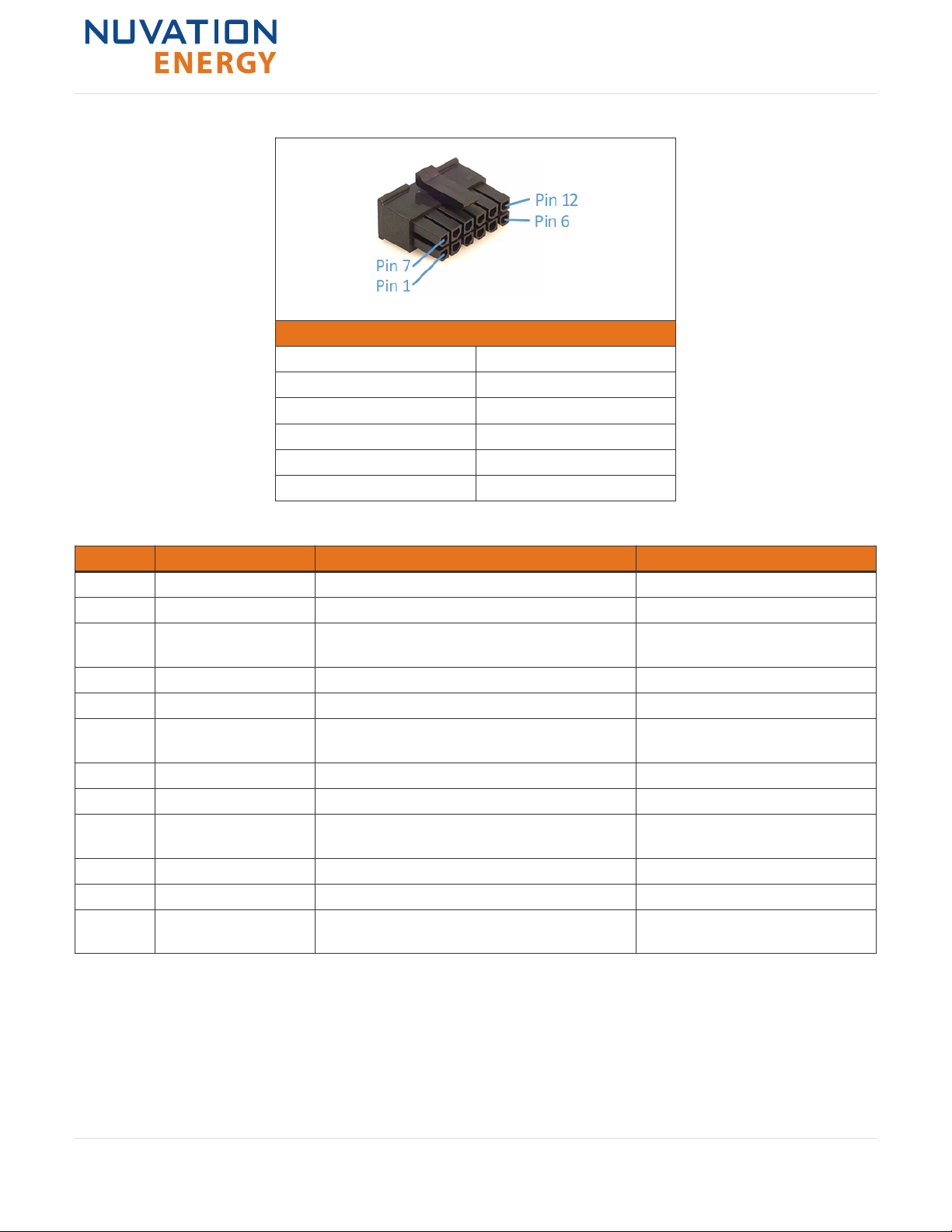
4.4.3. Battery Cells . . . . . . . . . . . . . . . . . . . . . . . . . . . . . . . . . . . . . . . . . . . . . . . . . . . . . Ê16
Battery Cell Connecter for Cell Interface - 12 channel . . . . . . . . . . . . . . . . . . . . . . . . . . . Ê17
Battery Cell Connecter for Cell Interface - 16 channel . . . . . . . . . . . . . . . . . . . . . . . . . . . Ê20
Battery Cell Connecter for Cell Interface - 12V 4 channel . . . . . . . . . . . . . . . . . . . . . . . . . Ê23
4.5. Temperature Sensors . . . . . . . . . . . . . . . . . . . . . . . . . . . . . . . . . . . . . . . . . . . . . . . . . . Ê25
5. High-Voltage Power Interface . . . . . . . . . . . . . . . . . . . . . . . . . . . . . . . . . . . . . . . . . . . . . . . Ê27
5.1. Overview . . . . . . . . . . . . . . . . . . . . . . . . . . . . . . . . . . . . . . . . . . . . . . . . . . . . . . . . . . Ê27
5.2. Mechanical Dimensions. . . . . . . . . . . . . . . . . . . . . . . . . . . . . . . . . . . . . . . . . . . . . . . . . Ê27
5.3. Electrical Connections . . . . . . . . . . . . . . . . . . . . . . . . . . . . . . . . . . . . . . . . . . . . . . . . . Ê28
5.3.1. Contactors . . . . . . . . . . . . . . . . . . . . . . . . . . . . . . . . . . . . . . . . . . . . . . . . . . . . . . Ê28
5.3.2. Interlock. . . . . . . . . . . . . . . . . . . . . . . . . . . . . . . . . . . . . . . . . . . . . . . . . . . . . . . . Ê31
5.3.3. External Power . . . . . . . . . . . . . . . . . . . . . . . . . . . . . . . . . . . . . . . . . . . . . . . . . . . Ê32
5.3.4. Stack Bus . . . . . . . . . . . . . . . . . . . . . . . . . . . . . . . . . . . . . . . . . . . . . . . . . . . . . . . Ê33
5.3.5. Thermistor . . . . . . . . . . . . . . . . . . . . . . . . . . . . . . . . . . . . . . . . . . . . . . . . . . . . . . Ê34
5.3.6. Current Shunt . . . . . . . . . . . . . . . . . . . . . . . . . . . . . . . . . . . . . . . . . . . . . . . . . . . . Ê34
5.3.7. Stack Power . . . . . . . . . . . . . . . . . . . . . . . . . . . . . . . . . . . . . . . . . . . . . . . . . . . . . Ê35
6. Nuvation Energy BMS: Best Practices . . . . . . . . . . . . . . . . . . . . . . . . . . . . . . . . . . . . . . . . . . Ê37
6.1. Grounding. . . . . . . . . . . . . . . . . . . . . . . . . . . . . . . . . . . . . . . . . . . . . . . . . . . . . . . . . . Ê37
6.2. Excess Cable Management . . . . . . . . . . . . . . . . . . . . . . . . . . . . . . . . . . . . . . . . . . . . . . Ê38

6.3. System Noise . . . . . . . . . . . . . . . . . . . . . . . . . . . . . . . . . . . . . . . . . . . . . . . . . . . . . . . Ê38
6.3.1. DC Filtering. . . . . . . . . . . . . . . . . . . . . . . . . . . . . . . . . . . . . . . . . . . . . . . . . . . . . . Ê39
6.3.2. Stack Controller Grounding. . . . . . . . . . . . . . . . . . . . . . . . . . . . . . . . . . . . . . . . . . . Ê40
6.3.3. Link Bus Power . . . . . . . . . . . . . . . . . . . . . . . . . . . . . . . . . . . . . . . . . . . . . . . . . . . Ê41
Appendix A: Factory Reset . . . . . . . . . . . . . . . . . . . . . . . . . . . . . . . . . . . . . . . . . . . . . . . . . . . Ê42
Overview. . . . . . . . . . . . . . . . . . . . . . . . . . . . . . . . . . . . . . . . . . . . . . . . . . . . . . . . . . . . . . Ê42
Reset to Factory Defaults . . . . . . . . . . . . . . . . . . . . . . . . . . . . . . . . . . . . . . . . . . . . . . . . . . Ê42

Important Safety Information
The content in this document must be followed in order to ensure safe operation of Nuvation
Energy BMS.
Do NOT energize the system until all connections to the Cell Interface and
Power Interface modules have been made.
Insulated handling is required of any connector carrying potentials over 600 V
DC relative to chassis.
Properly insulate or remove any unused wires. Unused wires can couple
excessive system noise into Nuvation Energy BMS which can disrupt
communication and lead to undesirable behaviors.
Please be aware of high voltages present in your system and follow all
necessary safety precautions.
The provided module enclosures are not fire enclosures.
Depending on battery chemistry, there might be a nominal voltage per cell
which adds up in series and is always present. There are many different
battery chemistries with different current capacities, and so high voltage with
high current capacity may be present while connecting Nuvation Energy BMS.
You must use proper electrical safety precautions when handling any part of
Nuvation Energy BMS.
Neither Nuvation Energy or any of its employees shall be liable for any direct,
indirect, incidental, special, exemplary, personal or consequential harm or
damages (including, but not limited to, procurement or substitute goods or
services; loss of use, data, or profits; or business interruption) however caused
and on any theory of liability, whether in contract, strict liability, or tort
(including negligence or otherwise) arising in any way out of the use of this
product.
Nuvation Energy BMS relies on your system charger to charge the battery
cells; do not leave your charger off while Nuvation Energy BMS is powered
from the stack for prolonged periods of time. Nuvation Energy BMS should be
shut down when the system is in storage to minimize the drain on the cells.
Nuvation Energy High-Voltage BMS - Installation Guide
Document ID: NE-IG-001 1Rev 2.1, 2020-03-13

1. Introduction
Thank you for choosing Nuvation Energy BMS.
Nuvation Energy High-Voltage BMS is an enterprise-grade battery management system with features
that extend battery life, ensuring pack-level safety, data-analytics, and remote management.
You can take advantage of the highly configurable browser-based user interface and custom-tune
Nuvation Energy BMS to your specific target application.
1.1. About this Guide
This Nuvation Energy High-Voltage BMS: Installation Guide provides wiring instructions to connect
your Nuvation Energy High-Voltage BMS to your system.
Once you have successfully completed the installation process, please follow instructions in the
Operator Interface Manual for accessing and configuring the Nuvation Energy BMS Operator Interface.
We thrive on your feedback and what we build is driven by your input. Please submit support
tickets to support@nuvationenergy.com.
Nuvation Energy High-Voltage BMS - Installation Guide
Document ID: NE-IG-001 2Rev 2.1, 2020-03-13

2. System Overview
The Nuvation Energy High-Voltage BMS family includes several modules that operate together as a
complete system. Available modules are listed below.
Table 1. High-Voltage BMS Modules
Model Module Name
NUV100-SC High-Voltage Stack Controller
NUV100-PI-HE High-Voltage Power Interface
NUV100-CI-12-1 Cell Interface - 12 channel
NUV100-CI-16-1 Cell Interface - 16 channel
NUV100-CI-4M12-1 Cell Interface - 12V 4 channel
Generally, a single High-Voltage BMS system uses 1 Stack Controller, 1 Power Interface, and 1 or
more Cell Interface modules. An example configuration is shown in Figure 1
Figure 1. Nuvation Energy High-Voltage BMS System Overview
Nuvation Energy High-Voltage BMS - Installation Guide
Document ID: NE-IG-001 3Rev 2.1, 2020-03-13

3. High-Voltage Stack Controller
3.1. Overview
The High-Voltage Stack Controller module monitors and controls all Cell Interface modules in a single
battery stack. The built-in Stack Bus receives power and communication from the Power Interface
module. The Link Bus provides power and communication for all connected Cell Interface modules.
Ethernet, CAN and RS-485 (Modbus) are included. No high-voltage or high-current interfaces are
present on the Stack Controller, making this module easy and safe to connect to for service
operations.
There is only one model of the Stack Controller, the NUV100-SC.
3.2. Mechanical Dimensions
The overall dimensions of the Stack Controller are 104.4 mm X 121.58 mm X 40.6 mm.
It comes standard with DIN clips that enable the Stack Controller module to be securely mounted to
EN50022-compliant DIN rails. The clips add an extra 19.6 mm to the overall width of the Stack
Controller module, bringing it from 104.4 mm to 124 mm. The clips also hold the module
approximately 7 mm away from the inside lip of the DIN rail.
Extra space should be provided around the module to allow for easy installation/maintenance.
The Stack Controller weighs approximately 525 g.
Nuvation Energy High-Voltage BMS - Installation Guide
Document ID: NE-IG-001 4Rev 2.1, 2020-03-13

Figure 2. Mechanical Drawing of Stack Controller
3.3. Electrical Connections
The Stack Controller module has 7 connectors. Each connector is described in the following sections
in detail.
3.3.1. Link Out
The Link Out connector provides power and communication to the Cell Interface modules. The
amount of current supplied by this connector is the sum of current consumed by all Cell Interface
modules in the system. Connect the Cell Interface module which is measuring the most negative cell
in the stack to this connector.
Nuvation Energy High-Voltage BMS - Installation Guide
Document ID: NE-IG-001 5Rev 2.1, 2020-03-13

Table 2. Link Out: Molex Micro-Fit 3.0 Connector
Molex 43025-0400
Manufacturer Molex Incorporated
Housing 43025-0400
Housing material Nylon UL94V-0
Circuits 4
Crimp terminal 43030-0002
Wire gauge range AWG20-24 stranded
Table 3. Link Out Connector Pin Assignment
Pin Connection Description Connected to Device
1 VBUS DC power from Stack Controller, with Fault
Pilot Signal
Cell Interface
2 COM Power return from Stack Controller Cell Interface
3 IPA Link Bus differential pair plus Cell Interface
4 IMA Link Bus differential pair minus Cell Interface
3.3.2. CAN 485
The CAN 485 connector contains both isolated CAN and non-isolated RS-485 (Modbus) connections.
Isolated CAN requires 5.5-12 Vdc sourced from an external power supply to operate. 120 Ω
termination for CAN is added by connecting pins 3 and 9 together. 150 Ω termination for Modbus is
added by connecting pins 6 and 12 together.
Keep the termination wire length short for best results. Connect external equipment to this connector.
Nuvation Energy High-Voltage BMS - Installation Guide
Document ID: NE-IG-001 6Rev 2.1, 2020-03-13

Table 4. CAN 485: Molex Micro-Fit 3.0 Connector
Molex 43025-1200
Manufacturer Molex Incorporated
Housing 43025-1200
Housing material Nylon UL94V-0
Circuits 12
Crimp terminal 43030-0002
Wire gauge range AWG20-24 stranded
Table 5. CAN 485 Connector Pin Assignment
Pin Connection Description Connected to Device
1 -V_isoCAN Power return from Pin 7 External Equipment
2 CAN_N CAN bus differential pair negative External Equipment
3 EXTCAN_TERM1 Termination Resistor; Short to Pin 9 to add
120Ω bus termination
CAN 485 Connector
4 COM Power return from SC External Equipment
5 MODBUS_N MODBUS differential pair negative External Equipment
6 EXTMOD_TERM1 Termination Resistor; Short to Pin 12 to add
150Ω bus termination
CAN 485 Connector
7 +12V_isoCAN +5.5~12Vdc isolated CAN bus power External Equipment
8 CAN_P CAN bus differential part positive External Equipment
9 EXTCAN_TERM2 Termination Resistor; Short to Pin 3 to add
120Ω bus termination
CAN 485 Connector
10 +VSYS +24Vdc Power supply External Equipment
11 MODBUS_P MODBUS differential pair positive External Equipment
12 EXTMOD_TERM2 Termination Resistor; Short to Pin 6 to add
150Ω bus termination
CAN 485 Connector
3.3.3. Ethernet
The Ethernet connector is a standard RJ45 Ethernet jack. Connect external equipment to this
connector.
Table 6. Ethernet Connector Pin Assignment
Nuvation Energy High-Voltage BMS - Installation Guide
Document ID: NE-IG-001 7Rev 2.1, 2020-03-13

Pin Connection Description Connected to Device
1 TD_P Transmit differential pair positive External Equipment
2 TD_N Transmit differential pair negative External Equipment
3 RD_P Receive differential pair positive External Equipment
4 NUL45 Unused; connected to Pin 5 and terminated External Equipment
5 NUL45 Unused; connected to Pin 4 and terminated External Equipment
6 RD_N Receive differential pair negative External Equipment
7 NUL78 Unused; connected to Pin 8 and terminated External Equipment
8 NUL78 Unused; connected to Pin 7 and terminated External Equipment
3.3.4. GPIO-Out
The GPIO-Out connector provides 4 general-purpose outputs. 4 independent solid-state relays are
used to connect *_A pins to their corresponding *_B pins. Each output is rated for 60 V DC, 400 mA
max., and the signals connected to each output must be within 50 V DC from chassis/earth ground.
There is no polarity dependency between *_A and *_B pins.
Connect external equipment to this connector.
Table 7. GPO: Molex Micro-Fit 3.0 Connector
Molex 43025-1000
Manufacturer Molex Incorporated
Housing 43025-1000
Housing material Nylon UL94V-0
Circuits 10
Crimp terminal 43030-0002
Wire gauge range AWG20-24 stranded
Table 8. GPO Connector Pin Assignment
Pin Connection Description Connected to Device
1 GPO_ISO0_A Digital Output 0 External Equipment
2 GPO_ISO1_A Digital Output 1 External Equipment
3 GPO_ISO2_A Digital Output 2 External Equipment
4 GPO_ISO3_A Digital Output 3 External Equipment
Nuvation Energy High-Voltage BMS - Installation Guide
Document ID: NE-IG-001 8Rev 2.1, 2020-03-13

Pin Connection Description Connected to Device
5 COM Power return from SC External Equipment
6 GPO_ISO0_B Digital Output 0 External Equipment
7 GPO_ISO1_B Digital Output 1 External Equipment
8 GPO_ISO2_B Digital Output 2 External Equipment
9 GPO_ISO3_B Digital Output 3 External Equipment
10 No Connect Not Connected No Connect
3.3.5. GPIO-In
The GPIO-In connector provides 4 general-purpose inputs. 4 independent detector circuits are used,
driven by an on-board +5 V source. Each detector’s input is connected to its corresponding pin, and
paired with a COM reference pin per input. When switched on by an external connection, each input
will source about 12 mA to COM.
Connect external equipment to this connector. Connect a pin to its corresponding COM to turn the
input on.
Table 9. GPI: Molex Micro-Fit 3.0 Connector
Molex 43025-0800
Manufacturer Molex Incorporated
Housing 43025-0800
Housing material Nylon UL94V-0
Circuits 8
Crimp terminal 43030-0002
Wire gauge range AWG20-24 stranded
Table 10. GPI Connector Pin Assignment
Pin Connection Description Connected to Device
1 COM Power return from Stack Controller for GPI0 External Equipment
2 COM Power return from Stack Controller for GPI2 External Equipment
3 COM Power return from Stack Controller for GPI3 External Equipment
4 COM Power return from Stack Controller for GPI4 External Equipment
5 GPI_ISO0_K Input detector 0 External Equipment
6 GPI_ISO1_K Input detector 1 External Equipment
Nuvation Energy High-Voltage BMS - Installation Guide
Document ID: NE-IG-001 9Rev 2.1, 2020-03-13

Pin Connection Description Connected to Device
7 GPI_ISO2_K Input detector 2 External Equipment
8 GPI_ISO3_K Input detector 3 External Equipment
3.3.6. Stack Bus
The Stack Bus connector accepts power and provides a communication channel from the Power
Interface. The Stack Bus provides 42 mA to the Stack Controller plus the summation of current
consumed by all Cell Interface modules in the system (25 mA per CI-12 or 31 mA per CI-16). 120 Ω
termination must be added by connecting pins 1 and 4 together with a short length of wire (see Table
12).
Connect the Power Interface module to this connector.
Table 11. Stack Bus: Molex MiniFit Jr Connector
Molex 39-01-2065
Manufacturer Molex Incorporated
Housing 39-01-2065
Housing material Nylon UL94V-0
Circuits 6
Crimp terminal 39-00-0181
Wire gauge range AWG20-24 stranded
Table 12. Stack Bus Connector Pin Assignment
Pin Connection Description Connected to Device
1 TERM1 Termination Resistor; Short to Pin 4 to add
120Ω bus termination
Stack Bus Connector
2 STACKBUS_N Stack bus differential pair negative Power Interface
3 +VSYS +24V Power Supply Power Interface
4 TERM2 Termination Resistor; Short to Pin 1 to add
120Ω bus termination
Stack Bus Connector
5 STACKBUS_P Stack bus differential pair positive Power Interface
6 COM Power return from SC Power Interface
Nuvation Energy High-Voltage BMS - Installation Guide
Document ID: NE-IG-001 10 Rev 2.1, 2020-03-13

4. Nuvation Energy Cell Interface
4.1. Overview
The Nuvation Energy Cell Interface connects to the battery cells and temperature sensors. The Cell
Interface monitors and balances the cells, sends cell data to the Stack Controller, and prevents
overheating or overcharging of cells.
There are three models of the Cell Interface.
▪The NUV100-CI-12-1, Cell Interface - 12 channel can monitor up to 12 series-connected cells
▪The NUV100-CI-16-1, Cell Interface - 16 channel can monitor up to 16 series-connected cells
▪The NUV100-CI-4M12-1, Cell Interface - 12V 4 channel can monitor up to 4 series-connected 12V
lead-acid cells
4.2. Mechanical Dimensions
4.3. Mechanical Overview
The overall dimensions of the Cell Interface are 104.4 mm X 121.58 mm X 40.6 mm.
The Cell Interface is available in a bulkhead-mountable enclosure as shown in Figure 3. The enclosure
has five metal walls, leaving the bottom of the unit fully exposed. It must be mounted to a metal
bulkhead panel such that the panel covers the exposed bottom side.
The NUV100-CI-12-1 and NUV100-CI-16-1 variants produce up to 24 W and 32 W, respectively,
during cell balancing. A portion of this heat is transferred to the bulkhead.
Extra space should be provided around the module to allow for easy installation/maintenance.
The standard Cell Interface, Bulkhead weighs approximately 450 g.
The Cell Interface contains high-voltage signals reaching as high as 1250 V DC. Care
must be taken when mounting the PCB into a metal enclosure to ensure that the
metal walls remain a safe distance from the exposed conductor on the PCB.
Using 1250 V DC as an example, the metal walls of the enclosure must be at least
4.2 mm from the nearest exposed conductor and must not touch the PCB or any
component on the PCB, including the connector housings.
Nuvation Energy High-Voltage BMS - Installation Guide
Document ID: NE-IG-001 11 Rev 2.1, 2020-03-13

Figure 3. Mechanical Drawing of Cell Interface with Bulkhead Enclosure
4.3.1. Optional DIN rail mounting Kit
For applications requiring DIN rail mounting, the Cell Interface may be ordered with the Cell Interface
Mounting Bracket (Bulkhead-to-DIN) kit. This kit is sold separately, and includes a metal plate and
the necessary hardware to securely mount the standard Cell Interface module to EN50022-compliant
DIN rails, as shown in Figure 4.
The Mounting Bracket kit assembly adds an extra 14.2 mm to the overall width of the Cell Interface
module, bringing it from 104.4 mm to 118.6 mm. The kit assembly holds the module approximately 7
mm away from the inside lip of the DIN rail.
The Mounting Bracket offsets the Cell Interface module from the center of the DIN rail approximately
30 mm upwards as shown in Figure 4.
A Cell Interface with the Mounting Bracket weighs approximately 540 g.
Nuvation Energy High-Voltage BMS - Installation Guide
Document ID: NE-IG-001 12 Rev 2.1, 2020-03-13

Figure 4. Mechanical Drawing of Cell Interface with Cell Interface Mounting Bracket
(Bulkhead-to-DIN)
NRND variant with DIN rail mounting
The older Cell Interface, DIN Mount variant has been discontinued and is NRND (not recommended
for new design). New designs should use Cell Interface, Bulkhead variant with the Cell Interface
Mounting Bracket (Bulkhead-to-DIN) kit. The information below is provided for the purpose of
updating DIN rail mechanical designs.
The clips add an extra 19.6 mm to the overall width of the standard Cell Interface module, bringing it
from 104.4 mm to 124 mm. The clips also hold the module approximately 7mm away from the inside
lip of the DIN rail. The DIN enclosure vertically centers the module over the DIN rail, as shown in
Figure 5.
A Cell Interface with DIN mountable enclosure weighs approximately 540 g.
Nuvation Energy High-Voltage BMS - Installation Guide
Document ID: NE-IG-001 13 Rev 2.1, 2020-03-13

Figure 5. Mechanical Drawing of Cell Interface with DIN Enclosure (NRND)
4.4. Electrical Connections
The Cell Interface module has 4 connectors. Each connector is described in the following sections in
detail.
4.4.1. Link Out
The Link Out connector provides power and communication to the Cell Interface modules above this
Cell Interface. The amount of current supplied by this connector is the sum of current consumed by
all Cell Interface modules above this Cell Interface.
Connect the Cell Interface that is measuring the next series-connected cell above the most positive
cell connected to this connector.
Nuvation Energy High-Voltage BMS - Installation Guide
Document ID: NE-IG-001 14 Rev 2.1, 2020-03-13

Table 13. Link Out: Molex Micro-Fit 3.0 Connector
Molex 43025-0400
Manufacturer Molex Incorporated
Housing 43025-0400
Housing material Nylon UL94V-0
Circuits 4
Crimp terminal 43030-0002
Wire gauge range AWG20-24 stranded
Table 14. Link Out Connector Pin Assignment
Pin Connection Description Connected to Device
1 VBUS DC power from Stack Controller, with Fault
Pilot Signal
Cell Interface
2 COM Power return from Stack Controller Cell Interface
3 IPA Link Bus differential pair plus Cell Interface
4 IMA Link Bus differential pair minus Cell Interface
4.4.2. Link In
The Link In connector provides power and communication to this Cell Interface from the Cell Interface
modules below this Cell Interface, or from the Stack Controller if this Cell Interface is measuring the
most negative cell in the stack.
The amount of current sourced into this connector is the sum of current consumed by this Cell
Interface and all those above it (which amounts to all Cell Interface modules if this Cell Interface is
measuring Cell 1).
Connect to the Link Out connector on the Cell Interface that is measuring the previous series-
connected cell below this Cell Interface to this connector, or connect the Stack Controller to this
connector if this Cell Interface is measuring the bottom cell in the stack.
Nuvation Energy High-Voltage BMS - Installation Guide
Document ID: NE-IG-001 15 Rev 2.1, 2020-03-13

Table 15. Link In: Molex Micro-Fit 3.0 Connector
Molex 43025-0400
Manufacturer Molex Incorporated
Housing 43025-0400
Housing material Nylon UL94V-0
Circuits 4
Crimp terminal 43030-0002
Wire gauge range AWG20-24 stranded
Table 16. Link In Connector Pin Assignment
Pin Connection Description Connected to Device
1 VBUS DC power from Stack Controller, with Fault
Pilot Signal
Cell Interface
2 COM Power return from Stack Controller Cell Interface
3 IPA Link Bus differential pair plus Cell Interface
4 IMA Link Bus differential pair minus Cell Interface
4.4.3. Battery Cells
The Battery Cells connector provides cell voltage input and a means for balancing the cells. The cable
wire should be rated for at least 750mA to survive worse-case current.
Pins 8, 16, 17, and 18 are No Connect in the Cell Interface - 12 channel model. Pins 2, 4, 6, 8, 10, 11,
12, 13, 14, 15, 16, and 17 are No Connect in the Cell Interface - 12V 4 channel model.
All unused voltage inputs should be tied to the next highest potential voltage sense input. In this way,
all pins should be connected with the exception of pins 8, 16, 17 and 18 in the Cell Interface - 12
channel model and pins 2, 4, 6, 8, 10, 11, 12, 13, 14, 15, 16, and 17 in the Cell Interface - 12V 4
channel model.
Connect the battery cell voltage sense leads to this connector.
Table 17. Battery Cells: Molex Micro-Fit 3.0 Connector
Nuvation Energy High-Voltage BMS - Installation Guide
Document ID: NE-IG-001 16 Rev 2.1, 2020-03-13

Molex 43025-1800
Manufacturer Molex Incorporated
Housing 43025-1800
Housing material Nylon UL94V-0
Circuits 18
Crimp terminal 43030-0002
Wire gauge range AWG20-24 stranded
Battery Cell Connecter for Cell Interface - 12 channel
Table 18. Cell Interface - 12 channel Battery Cell Connector Pin Assignment
Pin Connection Description Connected to Device
1 CELL0 Bottom reference of Cell Interface Connect to negative terminal of
the lowest cell (Cell 1)
2 CELL2 Cell 2 voltage sense Connect to positive terminal of
Cell 2
3 CELL4 Cell 4 voltage sense Connect to positive terminal of
Cell 4
4 CELL6 Cell 6 voltage sense Connect to positive terminal of
Cell 6
5 CELL8 Cell 8 voltage sense Connect to positive terminal of
Cell 8
6 CELL10 Cell 10 voltage sense Connect to positive terminal of
Cell 10
7 CELL12 Cell 12 voltage sense Connect to positive terminal of
Cell 12
8 No Connect Not Connected No Connect
9 No Connect Not Connected No Connect
10 CELL1 Cell 1 voltage sense Connect to positive terminal of
the lowest cell (Cell 1)
11 CELL3 Cell 3 voltage sense Connect to positive terminal of
Cell 3
12 CELL5 Cell 5 voltage sense Connect to positive terminal of
Cell 5
13 CELL7 Cell 7 voltage sense Connect to positive terminal of
Cell 7
Nuvation Energy High-Voltage BMS - Installation Guide
Document ID: NE-IG-001 17 Rev 2.1, 2020-03-13
Table of contents
Other Nuvation Energy Control System manuals
Popular Control System manuals by other brands

DELTA DORE
DELTA DORE TYXIA 6410 manual

ViSAGE
ViSAGE VIS2421 user manual

Lennox
Lennox Harmony III INSTALLATION, SETUP AND USER GUIDE

Painless
Painless Trail Rocker installation instructions

Schnick-Schnack-Systems
Schnick-Schnack-Systems Pixel-Gate operating instructions

energy sentry
energy sentry 9312 Owners and installation manual

Schaudt
Schaudt Electroblock EBL 271 instruction manual

Vicon
Vicon NOVA Powerplus VP3466 Programming manual

Mitsubishi Electric
Mitsubishi Electric MAC-588IF-E installation guide

Revo
Revo TX341 operating instructions

Coelbo
Coelbo SPEEDMATIC SET ALT Installation and operating instructions

Florite
Florite 990X Training guide