Nuvve PowerPort EVSE Manual

Page 1 | v1.0 | Proprietary & Confidential
Wi-Fi Set-Up with
Ubiquity Nano Station
OVERVIEW
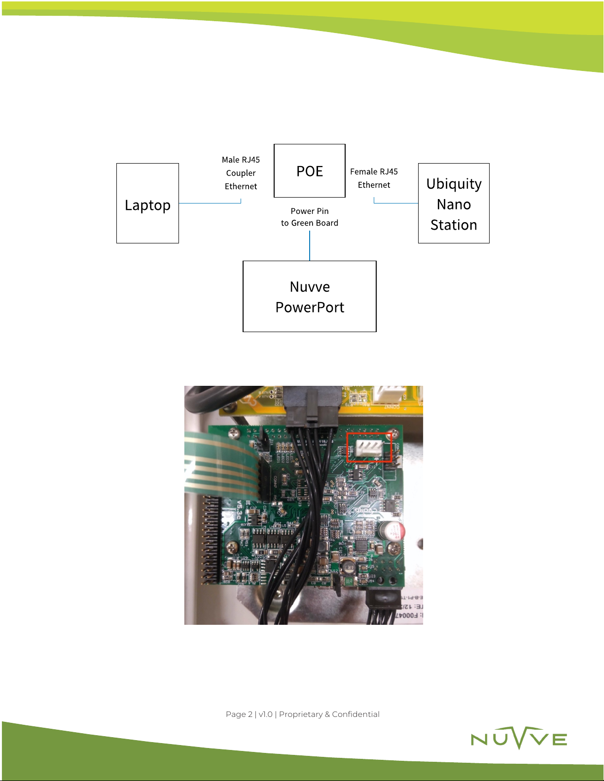
This document provides a step-by-step procedure for pairing the Nuvve PowerPort to a Wi-Fi
access point through the use of a Ubiquity NanoStation Loco M2. The NanoStation Loco M2
has been previously set up by Nuvve personnel, minimal setup is required by the user to allow
the Nuvve PowerPort access to the local Wi-Fi network where the EVSE will be in service.
EQUIPMENT/TOOLS
Provided by Nuvve:
• Nuvve PowerPort EVSE
• Ubiquity Nano Station Loco M2
• Power Over Ethernet (POE) Adapter
To be provided/sourced by user:
• Laptop with ethernet port (RJ45)
• 2 LAN cables (one to remain onsite & one for set up purposes)
• 1 Ethernet cable coupler (set up only)
• 4 RJ45 connectors
• Crimping Tool

Page 2 | v1.0 | Proprietary & Confidential
STEP 1:
Establish the correct hardware set-up as shown below
Image 1: Overview of wi-fi pairing hardware set-up
Image 2: Green board power pin where POE power pin will be connected
Nuvve
PowerPort
Ubiquity
Nano
Station
Laptop
POE
Male RJ45
Coupler
Ethernet
Female RJ45
Ethernet
Power Pin
to Green Board

Page 3 | v1.0 | Proprietary & Confidential
Image 3: POE adapter with male RJ45 (blue circle), female RJ45 (red circle), and power pin (yellow circle)
Image 4: Wi-Fi pairing hardware set-up completed

Page 4 | v1.0 | Proprietary & Confidential
Image 5: Set-up close-up with ethernet coupler (purple circle)
The POE Power Pin connects into the green board power connector (shown in image #2). Use
an ethernet cable to connect the female RJ45 terminal of the POE adapter to the Ubiquity
NanoStation Loco M2 LAN connector. Use an ethernet coupler to connect the male RJ45 of
the POE adapter to a laptop.
Once the Wi-Fi Pairing Hardware Set Up is complete move onto step 2 to begin the pairing
by accessing the Ubiquity NanoStation Loco M2 system set up.

Page 5 | v1.0 | Proprietary & Confidential
STEP 2:
Access Ubiquity system set-up and lock to access point
Turn off the Wi-Fi antenna on the laptop. Open up any browser and type
192.168.237.1
into the
search bar to access Ubiquity airOS Login Screen.
Image 6: Ubiquity airOS login screen
On Ubiquity airOS type the following to access NanoStation Loco M2 set up screen:
User Name:
ubnt
Password:
contact
for password
Image 7: NanoStation Loco M2 set-up screen (yellow circle)
Go to the wireless tab shown on image #7. Once inside the wireless settings window, on the
SSID field click select as shown in the image below.

Page 6 | v1.0 | Proprietary & Confidential
Image 8: Wireless settings window

Page 7 | v1.0 | Proprietary & Confidential
Image 9: Wireless scanning window
Once you click select, an Access Point Scanning window will open. Locate your Wi-Fi router
SSID and select it and click “Lock to AP” found at the bottom of the screen. On Image # 9 we
have selected NET2_G and are ready to lock to the Access Point. Select Lock to AP (blue box)
to continue.
!

Page 8 | v1.0 | Proprietary & Confidential
!
Image 10: Change Wi-Fi settings screen
!
After locking to the desired access point, key in the WPA of the Wi-Fi (green box found under
Wireless Security) then select “Change” (red box) found the bottom right of the screen as
shown on image above.
!

Page 9 | v1.0 | Proprietary & Confidential
Image 11: Apply changes screen
Apply changes by selecting the “Apply” button at the top of the screen as shown on the image
above (red box).

Page 10 | v1.0 | Proprietary & Confidential
Once the connection is established, go to the Main Tab as shown on the image below. Inside
the Main Tab you can find details of your WLAN connection such as Signal Strength and
Speed.
Image 12: Main window

Page 11 | v1.0 | Proprietary & Confidential
STEP 3:
Set up the permanent hardware connection between the Nuvve PowerPort and
Uniquity Nano Station Loco M2
Image 13: Overview of final Wi-Fi pairing hardware set-up
From Ubiquity NanoStation LAN port, connect an ethernet line to Female RJ45 and the Male
RJ45 of POE to the Ethernet port on the red board of the Nuvve PowerPort located beneath
the green board.
Image 14: Male Rj45 POE adapter end connected to ethernet port location (red circle)
Nuvve
PowerPort
Ubiquity
Nano
Station
POE
Male RJ45 Female RJ45
Power Pin
to Green Board
Redboard
Ethernet plug
(beneath
greenboard on
PowerPort)
Ethernet

Page 12 | v1.0 | Proprietary & Confidential
Image 15: Ideal placement of ethernet wire
Run the ethernet between the NanoStation and the POE Female RJ45 connector through
the left of the chassis as shown on the image above. Run the ethernet line out through the
whole located at the bottom right (blue circle) next to the charging cable. Once out of the
chassis, direct the line towards the Nano Station LAN Port.

Page 13 | v1.0 | Proprietary & Confidential
Image 16: Ethernet wire placement within PowerPort
Run the ethernet cable out of the bottom whole prior to terminating with RJ45 connectors.
Use straight-through cable. Fasten the cable run so that it is secure and not loose/dangling to
wall or mounting pole.

Page 14 | v1.0 | Proprietary & Confidential
ADDITIONAL SUPPORT
If you have any additional questions regarding set-up, feel free to contact the Nuvve support
team at [email protected].
Our team will gladly assist you in any of your EVSE vehicle-to-grid needs.
Thank you!
Table of contents
Other Nuvve Batteries Charger manuals