NI PXIe-4353 User manual

INSTALLATION GUIDE AND TERMINAL BLOCK
SPECIFICATIONS
NI PXIe-4353 and TC-4353
NI SC Express is a family of PXI Express modules with integrated data acquisition and signal
conditioning. These devices offer increased speed, accuracy, and synchronization features that
are well suited for high-density sensor measurement and signal-conditioning systems. The
TC-4353 rack-mount terminal block accessories provides thermocouple plug-in terminal
connectivity.
This guide describes how to install and configure the NI PXIe-4353 module and TC-4353
terminal block, thermocouple connector signals, and verify that the system is working properly.
Current versions of NI documents are available at ni.com/manuals.
The NI PXIe-4353 is a high-accuracy thermocouple input module that supports up to
32 thermocouple inputs and has 8 cold-junction compensation (CJC) channels for improved CJC
accuracy. The TC-4353 terminal block has eight thermistors that provide CJC for
thermocouples.
The TC-4353 terminal block is designed for use with the following module as specified:
NI PXIe-4353 ................................................... ±80 mV maximum voltage measurement range
Caution Do not supply hazardous voltages (>30 Vrms/42.4 Vpk/60 VDC) to the
TC-4353 terminal block.
Note Refer to the NI PXIe-4353 Specifications document for additional voltage and
safety information.
The keying of this terminal block prevents it from connecting to other modules that could be
damaged by the voltage present on the terminal block. However, you should only use this
terminal block with its supported modules.

2|ni.com |NI PXIe-4353 and TC-4353
Contents
What You Need to Get Started ................................................................................................. 3
Installation ................................................................................................................................3
Step 1. Install the Software ...............................................................................................3
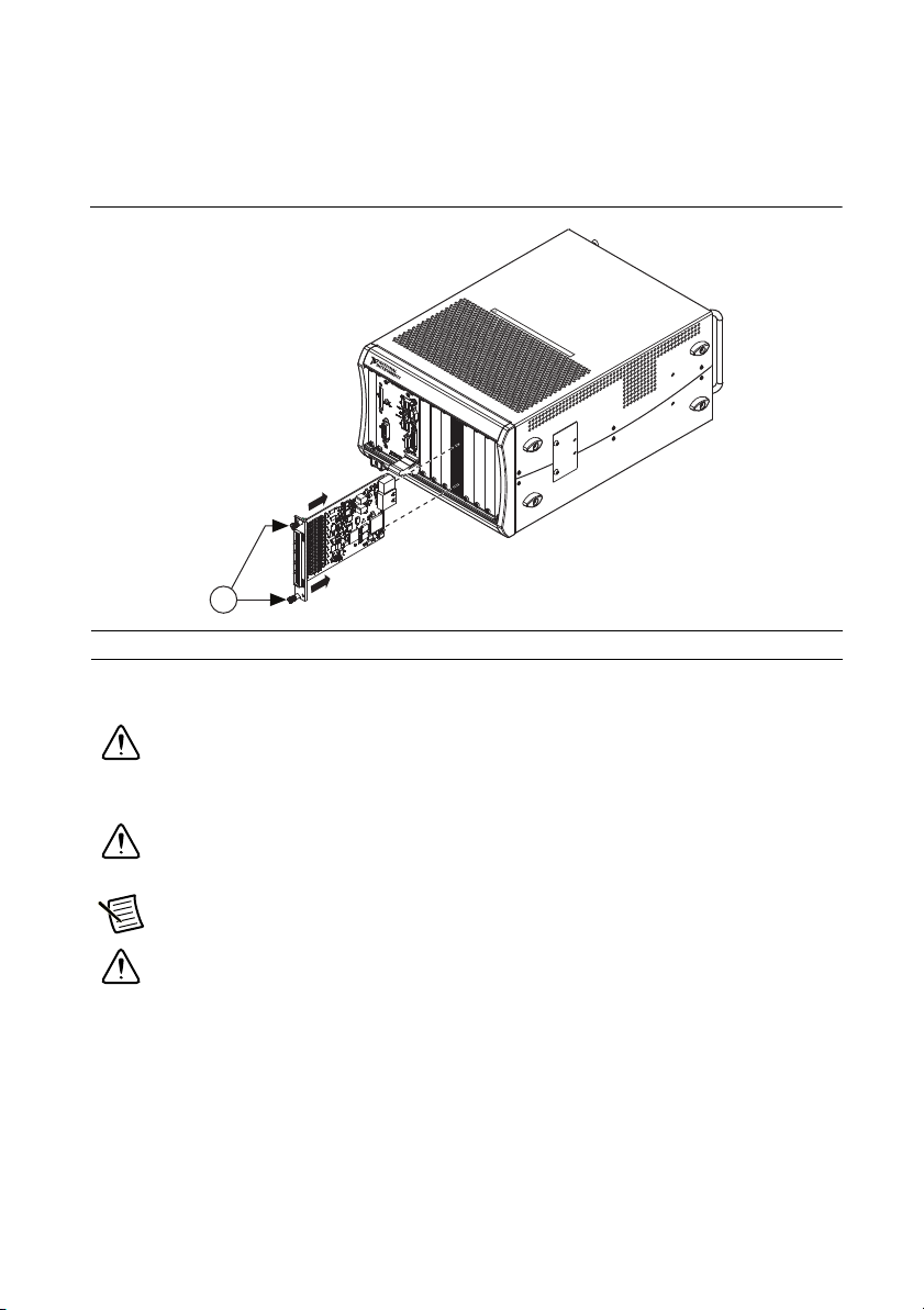
Step 2. Unpack and Install the Module............................................................................. 4
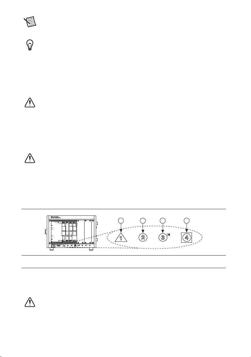
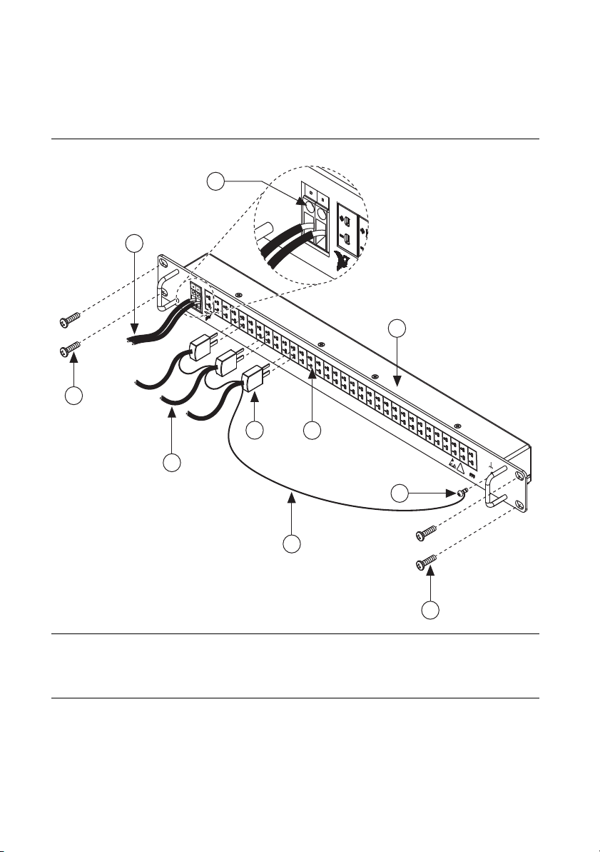
Step 3. Install the Terminal Block, Chassis, and Cables .................................................. 5
Step 4. Confirm NI SC Express Module Recognition ...................................................... 9
Step 5. Run Test Panels .................................................................................................... 10
Step 6. Take an NI-DAQmx Measurement ...................................................................... 10
NI-DAQmx Channels and Tasks .............................................................................. 10
Configure a Task Using the DAQ Assistant from MAX.......................................... 10
Step 7. Use Your NI SC Express 4353 in an Application ................................................11
Programming Examples............................................................................................ 11
Removal .................................................................................................................................... 12
Step 1. Remove the Terminal Block and Cables ..............................................................12
Step 2. Remove the Module..............................................................................................12
Create a Simulated Device........................................................................................................13
Cold-Junction Compensation....................................................................................................14
Minimizing Thermal Gradients ........................................................................................15
Calibrate the Module and Terminal Block ...............................................................................15
More Information......................................................................................................................16
Troubleshooting ................................................................................................................ 16
Specifications............................................................................................................................ 16
Calibration ........................................................................................................................16
Electrical ...........................................................................................................................16
Mechanical........................................................................................................................18
Physical .............................................................................................................................18
Environmental Specifications ...........................................................................................18
Operating Environment............................................................................................. 18
Storage Environment ........................................................................................................19
Shock and Vibration .........................................................................................................19
Safety Voltages .................................................................................................................19
Safety Standards ............................................................................................................... 20
Electromagnetic Compatibility ................................................................................................. 20
CE Compliance ................................................................................................................. 20
Online Product Certification.............................................................................................21
Environmental Management.............................................................................................21
Worldwide Technical Support ..................................................................................................21

NI PXIe-4353 and TC-4353 |© National Instruments |3
What You Need to Get Started
To set up and use the TC-4353 rack-mount terminal block with the NI PXIe-4353 module, you
need the following items:
• Hardware
– TC-4353 rack-mount terminal block
– NI PXIe-4353 module
–PXIechassis
– 19 in. rack to accommodate the TC-4353 and NI PXIe-4353
– Four 10-32 screws of a length suitable for your application (not supplied by NI)
– SH96-96-1 cable and included standoffs
– Rack-mount kit (as required for your application)
– Shielded thermocouple wire and thermocouple miniconnectors as required for your
application
• Tools
– Phillips-head and flathead screwdrivers as required by your application
– Wire cutter
– Wire insulation stripper
• Documentation
–NI PXIe-4353 and TC-4353 Installation Guide and Terminal Block Specifications
–Read Me First: Safety and Electromagnetic Compatibility
–NI PXIe-4353 User Manual
– PXIe chassis user manual
You can download needed documents from ni.com/manuals.
Installation
Step 1. Install the Software
Note You must be an administrator to install NI software and devices on your
computer.
Before installing the NI SC Express hardware, make sure the following are installed in the order
indicated:
1. Your application software, such as LabVIEW, LabWindows™/CVI™, or .NET.
2. NI-DAQmx 9.6 or later.

4|ni.com |NI PXIe-4353 and TC-4353
Note When installing NI application software, such as NI LabVIEW, refer to the
NI-DAQmx Readme on the software disc for supported software versions. Back up
any applications before upgrading software or modifying the application.
Tip Using an NI-DAQmx simulated device, you can test NI-DAQmx applications
without installing hardware. Refer to the Create a Simulated Device section for
instructions for creating NI-DAQmx simulated devices.
Step 2. Unpack and Install the Module
Remove the packaging and inspect the module. Contact NI if the module is damaged. Do not
install a damaged module.
Caution The module is static sensitive. Always properly ground yourself and the
equipment when handling or connecting to the module.
Complete the following steps to install the NI SC Express module while referring to Figures 1
and 2:
1. Power off the PXI Express chassis. Refer to the chassis manual for chassis installation and
configuration instructions.
Caution Refer to the Read Me First: Safety and Electromagnetic Compatibility,
included with your module, before connecting or disconnecting signal wires.
2. Identify a supported PXI Express slot in the chassis. NI SC Express devices can be placed
only in PXI Express Peripheral slots, PXI Express Hybrid Peripheral slots, and
PXI Express System Timing slots. Refer to the chassis documentation for details.
Figure 1. Symbols for PXI Express/PXI Express Hybrid/PXI Slots
3. Remove the filler panel and touch any metal part of the chassis to discharge static
electricity.
4. Place the module edges into the module guides at the top and bottom of the slot.
Caution When installing the module, make sure both edges are positioned inside
the guides and that the module components do not come into contact with adjacent
modules.
1 PXI Express System Controller Slot
2 PXI Peripheral Slot
3 PXI Express Hybrid Peripheral Slot
4 PXI Express System Timing Slot
NI PXIe-1062Q
1 2 34

NI PXIe-4353 and TC-4353 |© National Instruments |5
5. Slide the module along the guides until it reaches the rear connector, then seat the module
by pushing the front panel until it is flush with the front panel of the chassis.
6. Secure the module to the chassis using the front-panel captive screws, shown in Figure 2.
Tighten the screws to 0.31 N ·m (2.7 lb · in.).
Figure 2. Installing NI SC Express Modules
Step 3. Install the Terminal Block, Chassis, and Cables
Caution Refer to the Read Me First: Safety and Electromagnetic Compatibility
document before removing equipment covers or connecting or disconnecting any
signal wires.
Caution Do not supply hazardous voltages (>30 Vrms/42.4 Vpk/60 VDC) to the
terminal block.
Note The chassis can be powered on or off when installing the terminal block.
Caution To ensure the EMC performance specified for the connected
NI PXIe-4353 module, operate this product only with shielded thermocouple wires.
To install the rack-mount terminal block into the rack, complete the following steps while
referring to Figure 3.
1. Mount the TC-4353 in the desired position by installing and tightening the
four rack-mounting screws.
1CaptiveScrews
NI PXIe-1062Q
COOLING CLEARANCE AND FANFILTER MAINTENANCE REQUIRED. SEE MANUAL.COOLING CLEARANCE AND FANFILTER MAINTENANCE REQUIRED. SEE MANUAL.
1

6|ni.com |NI PXIe-4353 and TC-4353
If the chassis is not already installed in the rack, complete the following steps:
1. Attach the PXIe chassis rack-mount hardware to the NI PXIe chassis according to the
rack-mount hardware instructions.
2. Mount the PXIe chassis in the rack in the desired position.
Figure 3. TC-4353 Installation and Front Connections
1 Rack-Mounting Screws (4)
2 To Thermocouple Sensors
3 Thermocouple Miniconnector
4 Thermocouple Miniconnector Receptacle
5 Shield Drain Wire
6 Chassis Ground Screw
7 TC-4353 Rack-Mount Terminal Block
8 COM Terminals
9ToCOM
NATIONAL
INSTR M
UENTS
TC0 TC1 TC2 TC3TC4 TC5 TC6 TC7 TC8TC9 TC10 TC11 TC12 TC13TC14 TC15 TC16 TC17 TC18TC19 TC20 TC21 TC22 TC23TC24 TC25 TC26 TC27 TC28TC29 TC30TC31
COM
1
0
TC-4353 32 ChThermocouple Accessory
60V
!
N
I
TC0 TC1COM
10
6
4
3
2
1
9
8
7
1
5

NI PXIe-4353 and TC-4353 |© National Instruments |7
To install the cables, complete the following steps while referring to Figures 3 and 4.
Note For safety purposes and to prevent damage to equipment when high voltages
are present, the SH96-96-1 cable is keyed to prevent connection between
incompatible terminal blocks, modules, and/or cables.
1. Connect the shield drain wire of the shielded thermocouple wire to the chassis ground
screw, shown daisy chained in Figure 3. Make the shield drain wire as short as practical for
your application.
2. Connect the COM wires to the COM terminals.
3. Connect the thermocouple miniconnectors to the appropriate thermocouple miniconnector
receptacles.
4. Screw the two standoffs into the NI PXIe-4353 module. Tighten the standoffs to 0.90 N ·m
(8.0 lb · in.).
5. Connect the male end of the SH96-96-1 cable to the TC-4353 and tighten the two jack
screws to 0.90 N ·m(8.0lb·in.).
6. Connect the female end of the SH96-96-1 cable to the NI PXIe-4353 and tighten the
two jack screws to 0.90 N ·m(8.0lb·in.).
For information about CJC and accuracy considerations refer to the Cold-Junction
Compensation section.
Note For information about sensors, go to ni.com/sensors.

8|ni.com |NI PXIe-4353 and TC-4353
Figure 4. SH96-96-1 Cable and Standoff Installation
7. Power on the PXIe chassis if it is powered off.
1 SH96-96-1 Cable TC-4353 Connector Plug
2 TC-4353 Connector Receptacle
3 TC-4353 Rack-Mount Terminal Block
4 PXI Controller
5 PXIe Chassis
6 NI PXIe-4353 Module
7 Standoffs (2)
8 Jack Screws (4x)
9 SH96-96-1 Cable NI PXIe-4353 Connector Plug
NI PXIe-1062Q
COOLING CLEARANCE AND FAN FILTER MAINTENANCE REQUIRED.SEE MANUAL.COOLINGCLEARANCEANDFANFILTERMAINTENANCEREQUIRED.SEEMANUAL.
5
3
1
7
9
8
8
8
8
6
2
4

NI PXIe-4353 and TC-4353 |© National Instruments |9
Step 4. Confirm NI SC Express Module Recognition
To confirm module recognition, complete the following steps:
Note Make sure you are using the most recent version of NI-DAQmx. If you are
using an older version of the driver software, the NI SC Express terminal block may
work only in basic functionality mode. Unsupported terminal blocks appear in
Measurement & Automation Explorer (MAX) with an X next to them.
1. Launch MAX.
2. Expand Devices and Interfaces»NI-DAQmx Devices to confirm that MAX detects the
module and terminal block. The terminal block should appear beneath its associated
module. If your module or terminal block is not listed, press <F5> to refresh MAX. If the
module is still not recognized, go to ni.com/support/daqmx.
Tip Using an NI-DAQmx simulated device, you can test NI-DAQmx applications
without installing hardware. Refer to the Create a Simulated Device section for
instructions for creating NI-DAQmx simulated devices.
3. Right-click the module name and select Self-Test. When the self-test completes, a
verification message appears. If an error occurs, refer to ni.com/support/daqmx.
For information about sensors, go to ni.com/sensors.

10 |ni.com |NI PXIe-4353 and TC-4353
Step 5. Run Test Panels
1. In MAX, expand Devices and Interfaces»NI-DAQmx Devices.
2. Right-click the device, and select Test Panels.
3. Click Start to test device functions, or Help for operating instructions.
To troubleshoot errors, refer to the NI-DAQmx Help, or go to ni.com/support.
Step 6. Take an NI-DAQmx Measurement
NI-DAQmx Channels and Tasks
Refer to the NI-DAQmx Help for complete information about channels and tasks.
Use the DAQ Assistant to configure virtual channels and tasks in MAX or in your application.
Configure a Task Using the DAQ Assistant from MAX
Complete the following steps to create a task using the DAQ Assistant in MAX:
1. In MAX, right-click Data Neighborhood and select Create New to open the
DAQ Assistant.
2. Select NI-DAQmx Task and click Next.
3. Select Acquire Signals.
Note The NI PXIe-4353 cannot generate signals.
4. Select Analog Input and the measurement type, such as Temperature»Thermocouple
or Voltage.
5. Select the physical channel(s) to use and click Next.
6. Name the task and click Finish.
7. Configure the individual channel settings. Each physical channel you assign to a task
receives a virtual channel name. To modify the input range or other settings, select the
channel. Click Details for physical channel information. Configure the timing and
triggering for your task. Click Run.

NI PXIe-4353 and TC-4353 |© National Instruments |11
Step 7. Use Your NI SC Express 4353 in an Application
For NI software version compatibility, refer to the NI-DAQmx Readme, available from Start»
All Programs»National Instruments»NI-DAQmx.
To get started with data acquisition in your application software, refer to the tutorials listed in
Table 1.
Programming Examples
NI-DAQmx includes example programs to help you get started developing an application.
LabVIEW and CVI examples are located at Help»Find Examples in your application software.
Text-based code examples are located at All Programs»National Instruments»NI-DAQ»
Text-Based Code Support»ANSI C Examples. Modify example code and save it in an
application, or use examples to develop a new application or add example code to an existing
application.
For other examples, go to ni.com/info and enter the Info Code daqmxexp. For additional
examples, refer to zone.ni.com.
Table 1. DAQ Assistant Tutorial Locations
Application Tutorial Location
LabVIEW Go to Help»Search the LabVIEW Help. Next, go to Getting Started with
LabVIEW»Getting Started with DAQ»Taking an NI-DAQmx Measurement
in LabVIEW.
LabWindows/CVI Go to Help»Contents. Next, go to Using LabWindows/CVI»Data Acquisition»
Taking an NI-DAQmx Measurement in LabWindows/CVI.
Measurement
Studio
Go to NI Measurement Studio Help»Getting Started with the Measurement
Studio Class Libraries»Measurement Studio Walkthroughs»
Walkthrough: Creating a Measurement Studio NI-DAQmx Application.
LabVIEW
SignalExpress*
Go to Help»Taking an NI-DAQmx Measurement in SignalExpress.
*LabVIEW SignalExpress, an easy-to-use configuration-based tool for data logging applications, is at
Start»All Programs»National Instruments»LabVIEW SignalExpress.

12 |ni.com |NI PXIe-4353 and TC-4353
Removal
Step 1. Remove the Terminal Block and Cables
To remove the TC-4353 and NI PXIe-4353, complete the following steps while referring to
Figures 3 and 4:
Note The chassis can be powered on or off when removing the terminal block.
1. Remove the thermocouple miniconnectors, shield drain wires, and COM wires from the
terminal block.
2. Loosen the four jack screws and remove the SH96-96-1 cable from the terminal block and
the module.
Note If required for your application, remove the two standoffs from the module.
3. While supporting the terminal block, remove the four rack-mounting screws.
4. Remove the terminal block from the rack.
5. Store the terminal block in an antistatic protective bag.
Step 2. Remove the Module
Caution Do not remove a module with the power on. Doing so can damage the
module.
1. Make sure that the chassis is powered off before removing the module.
2. Loosen the captive screws on the top and bottom of the module.
Caution Do not pull the front panel to remove the module. Doing so may cause
module components to come into contact with adjacent modules, causing damage to
the modules.

NI PXIe-4353 and TC-4353 |© National Instruments |13
3. Pull the captive screws to unseat the module and slowly slide the module along the guides,
as shown in Figure 5.
4. Replace the filler panel in the empty slot.
5. Store the module in an antistatic protective bag.
Figure 5. Removing NI SC Express Modules
Create a Simulated Device
To run examples without the hardware installed, use an NI-DAQmx simulated device. To create
a simulated device in MAX:
1. Launch MAX.
2. Right-click Devices and Interfaces»Create New.
3. From the dialog, select Simulated NI-DAQmx Device or Modular Instrument.
4. Type 4353 in the text box at the top of the window.
5. Select the device from the list provided.
6. Click OK.
1 Captive Screws (Use to remove modules.) 2 Front Panel (Do not use to remove modules.)
NI PXIe-1062Q
COOLING CLEARANCE AND FANFILTER MAINTENANCE REQUIRED. SEE MANUAL.COOLINGCLEARANCE ANDFANFILTERMAINTENANCE REQUIRED. SEE MANUAL.
12

14 |ni.com |NI PXIe-4353 and TC-4353
Cold-Junction Compensation
Cold-junction compensation is the process of measuring the temperature of the junction for the
thermocouple and applying a representative compensating voltage to the voltage measured by
the thermocouple channel. The accuracy of the cold-junction temperature measurement is a key
part of the accuracy of the overall thermocouple temperature measurement. The TC-4353 is
carefully designed to ensure high-accuracy cold-junction temperature measurements, under a
variety of conditions; however, care must be taken to ensure the best possible accuracy. Refer to
the Minimizing Thermal Gradients section for guidelines to minimize thermal gradients that
could impact the CJC accuracy. Refer to the Specifications section for the CJC accuracy
specifications.
The TC-4353 contains eight thermistors that are used to measure the temperature of the adjacent
thermocouple junctions for the CJC that is performed when computing the thermocouple
temperature measurement. These eight thermistors are measured using the CJC channels on the
NI PXIe-4353 module. Each thermistor measures the CJC temperature for a subset of associated
thermocouple channels. Figure 6 shows the CJC grouping locations. The dashed lines indicate
the channel to CJC associations found in Table 2. NI-DAQmx automatically associates the
correct thermistor with the thermocouple measurements when you use the Thermocouple
Channel-Type and select built-in for the CJC source.
Figure 6. TC-4353 CJC Grouping Locations
1 CJC0
2 CJC1
3 CJC2
4 CJC3
5 CJC4
6 CJC5
7 CJC6
8 CJC7
Table 2. CJC to Thermocouple Channels Associations
CJC Associated Thermocouples CJC Associated Thermocouples
CJC0 TC <0..3> CJC4 TC <16..19>
CJC1 TC <4..7> CJC5 TC <20..23>
CJC2 TC <8..11> CJC6 TC <24..27>
CJC3 TC <12..15> CJC7 TC <28..31>
TC0 TC1 TC2 TC3TC4 TC5 TC6 TC7 TC8TC9 TC10 TC1 TC12 TC3TC14 TC15 TC16 TC17 TC18TC19 TC20 TC21 TC22 TC23TC24 TC25 TC26 TC27 TC28TC29 TC30TC31
+
–
+
–
+
–
+
–
+
–
+
–
+
–
+
–
+
–
+
–
+
–
+
–
+
–
+
–
+
–
+
–
+
–
+
–
+
–
+
–
+
–
+
–
+
–
+
–
+
–
+
–
+
–
+
–
+
–
+
–
+
–
+
–
12345678

NI PXIe-4353 and TC-4353 |© National Instruments |15
Minimizing Thermal Gradients
Thermal gradients can be caused by changes in the ambient air temperature near the terminal
block, heat sources from other devices near the terminal block, or by the thermocouple wire if it
conducts heat to or away from the terminal junctions. For optimal CJC accuracy performance,
ensure that changes in ambient temperature and temperature gradients near the terminal block
are kept to a minimum. Follow these guidelines to minimize thermal gradients that could impact
the CJC accuracy:
• Use the smallest gauge thermocouple wire suitable for the application. Smaller wire
transfers less heat to or from the terminal junction.
• Run thermocouple wiring together near the terminal block to keep the wires at the same
temperature.
• Avoid running thermocouple wires near hot or cold objects.
• If you connect any extension wires to thermocouple wires, use wires made of the same
conductive material as the thermocouple wires.
• Minimize adjacent heat sources and air flow across the terminal block.
• Keep the ambient temperature as stable as possible.
• Keep the terminal block, module, and chassis in a stable and consistent orientation.
• Install the PXIe filler panels in any unused slots.
• When stacking the system, avoid stacking the terminal block above a heat source as heat
rises and can introduce error.
• Allow the thermal gradients to settle after a change in system power or in ambient
temperature. A change in system power can happen when the system powers on. Refer to
the warm-up time in the NI PXIe-4353 Specifications for more information.
• Replace, clean, or remove the fan filters in the PXIe chassis regularly to ensure proper
system cooling.
Calibrate the Module and Terminal Block
You can download available external calibration documents from ni.com/calibration by
clicking Manual Calibration Procedures. For external calibration of products not listed there,
Basic Calibration Service or Detailed Calibration Service is recommended. You can get
information about both of these calibration services at ni.com/calibration.
NI recommends performing an external calibration once a year.

16 |ni.com |NI PXIe-4353 and TC-4353
More Information
After you install NI-DAQmx, the NI-DAQmx documentation is available from Start»
All Programs»National Instruments»NI-DAQ. Additional resources are online at ni.com/
gettingstarted.
You can access online device documentation by right-clicking your module in MAX and
selecting Help»Online Device Documentation. A browser window opens to ni.com/
manuals with the results of a search for relevant documents. If you do not have Web access,
documents for supported modules are included on the NI-DAQmx disc.
Troubleshooting
• Go to ni.com/support/install or ni.com/kb.
• If you need to return your National Instruments hardware for repair or device calibration,
go to ni.com/info and enter rdsenn to start the Return Merchandise Authorization
(RMA) process.
Specifications
Note NI PXIe-4353 module specifications are located in the NI PXIe-4353
Specifications document.
All specifications are typical for the range of 0 °C to 55 °C unless otherwise specified.
Calibration
Calibration interval ...........................................1 year
Electrical
Cold-junction sensors
Sensor type................................................NTC thermistor, 10 kΩnominal
Steinhart-Hart scaling coefficients1
A........................................................1.1288643 ×10–3
B........................................................2.3414908 ×10–4
C........................................................8.7706554 ×10–8
1 Refer to the software documentation for details about scaling the thermistor readings.

NI PXIe-4353 and TC-4353 |© National Instruments |17
CJC accuracy1
Input voltage range ........................................... Refer to the NI PXIe-4353 Specifications
document.
1 This includes the combined effects of the thermistor accuracy and the temperature difference between the
screw terminal and its associated thermistor. This represents performance for wire gauges of 20 AWG and
smaller.
Terminal Block
Typical*Maximum*
23 °C ±5 °C 0°Cto55°C 23 °C ±5 °C 0°Cto55°C
TC-4353,
Configuration A†
0.18 °C 0.25 °C 0.25 °C 0.37 °C
TC-4353,
Configuration B‡
— — 0.46 °C 0.51 °C
TC-4353,
Configuration C**
— — 1.90 °C 2.02 °C
*For graphs that combine CJC Accuracy with Voltage Measurement Accuracy to derive
overall thermocouple measurement accuracy, go to ni.com/info and use Info Code
PXIE4353CALCULATOR.
†Configuration A represents a TC-4353 deployed into a thermally isolated setup.
‡Configuration B represents a TC-4353 that is mounted below any heat sources in the rack
and is protected from airflow by a physical barrier.
** Configuration C represents a TC-4353 that has not been protected from heat sources.
Note: For example configurations go to ni.com/info and use Info Code
TC4353CONFIGURATIONS.

18 |ni.com |NI PXIe-4353 and TC-4353
Mechanical
Screw terminal wire gauge ...............................10 AWG to 24 AWG
Connectors ........................................................mini-thermocouple
Physical
Figure 7. TC-4353 Dimensions
Weight ...............................................................825 g (29.1 oz)
Environmental Specifications
Maximum altitude.............................................2,000 m (800 mbar)
Pollution Degree ...............................................2
Indoor use only.
Operating Environment
Ambient temperature range ..............................0 °C to 55 °C
(Tested in accordance with IEC-60068-2-1 and
IEC-60068-2-2. Meets MIL-PRF-28800F
Class 3 low temperature limit and
MIL-PRF-28800F Class 2 high temperature
limit.)
Relative humidity range....................................10% to 90%, noncondensing
(Tested in accordance with IEC-60068-2-56.)
NATIONAL
INST R M
UENTS
TC0 TC1 TC2 TC3TC4 TC5 TC6 TC7 TC8TC9 TC10 TC11 TC12 TC13TC14 TC15 TC16 TC17 TC18TC19 TC20 TC21 TC22 TC23TC24 TC25 TC26 TC27 TC28TC29 TC30TC31COM
10
TC-4353 32 ChThermocouple Accessory 60V
!
482.6 mm (19 in.)
36.97 mm
(1.456 in.)
43.94 mm
(1.730 in.)

NI PXIe-4353 and TC-4353 |© National Instruments |19
Storage Environment
Ambient temperature range .............................. –40 °C to 71 °C
(Tested in accordance with IEC-60068-2-1 and
IEC-60068-2-2. Meets MIL-PRF-28800F
Class 3 limits.)
Relative humidity range.................................... 5% to 95%, noncondensing
(Tested in accordance with IEC-60068-2-56.)
Shock and Vibration
Operating shock ................................................ 30 g peak, half-sine, 11 ms pulse
(Tested in accordance with IEC-60068-2-27.
Meets MIL-PRF-28800F Class 2 limits.)
Random vibration
Operating .................................................. 5 Hz to 500 Hz, 0.3 grms
Non-operating ........................................... 5 Hz to 500 Hz, 2.4 grms
(Tested in accordance with IEC-60068-2-64.
Non-operating test profile exceeds the
requirements of MIL-PRF-28800F, Class 3.)
Safety Voltages
Isolation (TC-4353)
Channel-to-channel................................... None
Channel-to-earth ground........................... 60 VDC, Measurement Category I
Measurement Category I is for measurements performed on circuits not directly connected to the
electrical distribution system referred to as MAINS voltage. MAINS is a hazardous live
electrical supply system that powers equipment. This category is for measurements of voltages
from specially protected secondary circuits. Such voltage measurements include signal levels,
special equipment, limited-energy parts of equipment, circuits powered by regulated
low-voltage sources, and electronics.
Caution Do not connect the TC-4353 to signals or use for measurements within
Measurement Categories II, III or IV.
Caution The protection provided by the TC-4353 can be impaired if it is used in a
manner not described in this document.
Caution Refer to the NI PXIe-4353 Specifications document for maximum voltage
limits. When used with the TC-4353, the isolation voltage is 60 V max from channel
or COM to earth ground.

20 |ni.com |NI PXIe-4353 and TC-4353
Safety Standards
This product meets the requirements of the following standards of safety for electrical equipment
for measurement, control, and laboratory use:
• IEC 61010-1, EN 61010-1
• UL 61010-1, CSA 61010-1
Electromagnetic Compatibility
This product meets the requirements of the following EMC standards for electrical equipment
for measurement, control, and laboratory use:
• EN 61326-1 (IEC 61326-1): Class A emissions; Basic immunity
• EN 55011 (CISPR 11): Group 1, Class A emissions
• EN 55022 (CISPR 22): Class A emissions
• EN 55024 (CISPR 24): Immunity
• AS/NZS CISPR 11: Group 1, Class A emissions
• AS/NZS CISPR 22: Class A emissions
• FCC 47 CFR Part 15B: Class A emissions
• ICES-001: Class A emissions
Caution For EMC compliance, operate this product with shielded cables and
accessories.
Note In the United States (per FCC 47 CFR), Class A equipment is intended for use
in commercial, light-industrial, and heavy-industrial locations. In Europe, Canada,
Australia and New Zealand (per CISPR 11) Class A equipment is intended for use
only in heavy-industrial locations.
Note Group 1 equipment (per CISPR 11) is any industrial, scientific, or medical
equipment that does not intentionally generate radio frequency energy for the
treatment of material or inspection/analysis purposes.
Note For EMC declarations and certifications, and additional information, refer to
the Online Product Certification section.
CE Compliance
This product meets the essential requirements of applicable European Directives as follows:
• 2006/95/EC; Low-Voltage Directive (safety)
• 2004/108/EC; Electromagnetic Compatibility Directive (EMC)
Other manuals for PXIe-4353
1
This manual suits for next models
1
Table of contents
Other NI Control Unit manuals
Popular Control Unit manuals by other brands

Dinel
Dinel PCU-100 Series user manual

Heatscope
Heatscope LIFT Original installation and instruction manual

ChargePoint
ChargePoint 28010077 installation instructions

APS
APS PreView VideoLink PVL4000 operating manual

Beninca
Beninca DREAMY operating instructions

Watts
Watts 757 Series Installation, maintenance & repair