OBO Bettermann PYROLINE Rapid User manual

11/2019 EN
PYROLINE® Rapid fire protection duct
Mounting instructions
Building Connections

© 2019 OBO Bettermann Holding GmbH & Co. KG
Reprinting, even of extracts, as well as photographic or electronic reproduction are prohibited!
PYROLINE® Rapid fire protection duct
Mounting instructions

Mounting instructions PYROLINE® Rapid fire protection duct EN | 3
Table of contents
Table of contents
1 About these instructions . . . . . . . . . . . . . . . . . . . . .5
1.1 Target group . . . . . . . . . . . . . . . . . . . . . . . . . . . . . . . 5
1.2 Using these instructions . . . . . . . . . . . . . . . . . . . . . . . . . 5
1.3 Types of safety information . . . . . . . . . . . . . . . . . . . . . . . . 5
1.4 Correct use . . . . . . . . . . . . . . . . . . . . . . . . . . . . . . . . 5
1.5 Applicable documents . . . . . . . . . . . . . . . . . . . . . . . . . . 6
1.6 Recommended documents . . . . . . . . . . . . . . . . . . . . . . . . 6
2 General safety information . . . . . . . . . . . . . . . . . . . .6
3 Product description . . . . . . . . . . . . . . . . . . . . . . . .7
3.1 Properties/functional method . . . . . . . . . . . . . . . . . . . . . . . 7
3.2 Testing and classification . . . . . . . . . . . . . . . . . . . . . . . . . 7
3.3 Overview of mounting types . . . . . . . . . . . . . . . . . . . . . . . 8
3.4 Fastening base . . . . . . . . . . . . . . . . . . . . . . . . . . . . . . 9
3.5 Cable assignment/maximum load . . . . . . . . . . . . . . . . . . . . 9
3.6 System overview . . . . . . . . . . . . . . . . . . . . . . . . . . . . 10
3.6.1 Duct width 250 mm, direct mounting . . . . . . . . . . . . . . . . . . . . . 10
3.6.2 Duct width 110 mm, direct mounting . . . . . . . . . . . . . . . . . . . . . 11
3.6.3 Duct width 70 mm, direct mounting . . . . . . . . . . . . . . . . . . . . . . 12
3.6.4 Duct width 250 mm, mounting on support system . . . . . . . . . . . . . . 13
3.6.5 Duct width 110 mm, mounting on support system . . . . . . . . . . . . . . 15
3.6.6 Duct width 70 mm, mounting on support system . . . . . . . . . . . . . . . 16
4 Mounting basics . . . . . . . . . . . . . . . . . . . . . . . . . 17
4.1 Fastening material . . . . . . . . . . . . . . . . . . . . . . . . . . . 17
4.2 Necessary tools . . . . . . . . . . . . . . . . . . . . . . . . . . . . . 18
4.3 Shortening cables. . . . . . . . . . . . . . . . . . . . . . . . . . . . 18
4.4 Inserting locking brackets . . . . . . . . . . . . . . . . . . . . . . . . 19
4.5 Using lid support . . . . . . . . . . . . . . . . . . . . . . . . . . . . 20
4.6 Routing cables . . . . . . . . . . . . . . . . . . . . . . . . . . . . . 21
5 Direct mounting on the ceiling, wall or floor . . . . . . . . . 22
5.1 Basic mounting procedure . . . . . . . . . . . . . . . . . . . . . . . 22
5.2 Mounting the fire protection duct on the ceiling . . . . . . . . . . . . . 22
5.3 Mounting the fire protection duct on the wall or floor . . . . . . . . . . 25
5.3.1 Mounting the fire protection duct on the floor . . . . . . . . . . . . . . . . . 26
5.3.2 Mounting the fire protection duct on the wall . . . . . . . . . . . . . . . . . 27
5.4 Connecting joints . . . . . . . . . . . . . . . . . . . . . . . . . . . . 28
5.5 Creating a wall/ceiling penetration . . . . . . . . . . . . . . . . . . . 29
5.5.1 Wall penetration in solid wall . . . . . . . . . . . . . . . . . . . . . . . . . 29
5.5.2 Wall penetration in dry/lightweight construction wall . . . . . . . . . . . . . 30
5.6 Mounting fittings . . . . . . . . . . . . . . . . . . . . . . . . . . . . 31
5.6.1 Mounting flat angles . . . . . . . . . . . . . . . . . . . . . . . . . . . . . 31
5.6.2 Mounting an external corner . . . . . . . . . . . . . . . . . . . . . . . . . 32
5.6.3 Mounting an internal corner . . . . . . . . . . . . . . . . . . . . . . . . . 32
5.6.4 Mounting a T branch piece . . . . . . . . . . . . . . . . . . . . . . . . . 33
5.6.5 Mounting a T reducing branch piece . . . . . . . . . . . . . . . . . . . . . 34
5.6.6 Mounting a reducer . . . . . . . . . . . . . . . . . . . . . . . . . . . . . . 36
5.6.7 Mounting a wall/ceiling penetration . . . . . . . . . . . . . . . . . . . . . . 36
5.6.8 Mounting an end piece . . . . . . . . . . . . . . . . . . . . . . . . . . . . 37
OBO Bettermann
4 | EN
Table of contents
6 Mounting on a support system . . . . . . . . . . . . . . . . . 38
6.1 Mounting a fire protection duct . . . . . . . . . . . . . . . . . . . . . 38
6.1.1 Mounting on a support profile . . . . . . . . . . . . . . . . . . . . . . . . 40
6.1.2 Mounting on a profile rail . . . . . . . . . . . . . . . . . . . . . . . . . . . 42
6.1.3 Mounting on a support/bracket . . . . . . . . . . . . . . . . . . . . . . . . 43
6.1.4 Mounting on a wall bracket . . . . . . . . . . . . . . . . . . . . . . . . . . 44
6.2 Creating a wall/ceiling penetration . . . . . . . . . . . . . . . . . . . 45
6.2.1 Wall penetration in solid wall . . . . . . . . . . . . . . . . . . . . . . . . . 46
6.2.2 Wall penetration in dry/lightweight construction wall . . . . . . . . . . . . . 47
6.3 Mounting fittings . . . . . . . . . . . . . . . . . . . . . . . . . . . . 48
6.3.1 Mounting flat angles . . . . . . . . . . . . . . . . . . . . . . . . . . . . . 48
6.3.2 Mounting an external corner . . . . . . . . . . . . . . . . . . . . . . . . . 50
6.3.3 Mounting an internal corner . . . . . . . . . . . . . . . . . . . . . . . . . 52
6.3.4 Mounting vertical bends . . . . . . . . . . . . . . . . . . . . . . . . . . . 54
6.3.5 Mounting a T branch piece . . . . . . . . . . . . . . . . . . . . . . . . . 56
6.3.6 Mounting a T reducing branch piece . . . . . . . . . . . . . . . . . . . . . 58
6.3.7 Mounting a reducer . . . . . . . . . . . . . . . . . . . . . . . . . . . . . . 60
6.3.8 Mounting a wall/ceiling penetration . . . . . . . . . . . . . . . . . . . . . . 62
6.3.9 Mounting an end piece . . . . . . . . . . . . . . . . . . . . . . . . . . . . 66
7 Creating cable outlets . . . . . . . . . . . . . . . . . . . . . 68
7.1 Creating an individual outlet . . . . . . . . . . . . . . . . . . . . . . 68
7.2 Creating a multiple outlet . . . . . . . . . . . . . . . . . . . . . . . . 68
7.3 Creating a rear-side cable outlet . . . . . . . . . . . . . . . . . . . . 71
8 Completing mounting . . . . . . . . . . . . . . . . . . . . . . 72
8.1 Create equipotential bonding . . . . . . . . . . . . . . . . . . . . . . 72
8.2 Tightness test . . . . . . . . . . . . . . . . . . . . . . . . . . . . . . 73
8.3 Completing the declaration of conformity . . . . . . . . . . . . . . . . 73
8.4 Attaching the identification plate . . . . . . . . . . . . . . . . . . . . 73
9 Installation at a later date . . . . . . . . . . . . . . . . . . . . 74
10 Mounting variants . . . . . . . . . . . . . . . . . . . . . . . . 74
10.1 Intersection with other systems . . . . . . . . . . . . . . . . . . . . . 74
10.2 Creating wall end covers . . . . . . . . . . . . . . . . . . . . . . . . 75
10.2.1 Wall penetration smaller than or the same size as the duct opening . . . . . 75
10.2.2 Wall penetration larger than the duct opening . . . . . . . . . . . . . . . . 76
10.2.3 Wall penetration for direct mounting . . . . . . . . . . . . . . . . . . . . . 77
11 Disposal . . . . . . . . . . . . . . . . . . . . . . . . . . . . . 78
11.1 Disposal during mounting . . . . . . . . . . . . . . . . . . . . . . . . 78
11.2 Disposal during building demolition . . . . . . . . . . . . . . . . . . . 78
11.3 Disposal after a fire . . . . . . . . . . . . . . . . . . . . . . . . . . . 78
12 Technical data . . . . . . . . . . . . . . . . . . . . . . . . . . 79
13 Appendix – declaration of conformity (sample). . . . . . . . 83

Mounting instructions PYROLINE® Rapid fire protection duct EN | 5
About these instructions
1 About these instructions
1.1 Target group
These instructions are aimed at trained installation engineers as well as
those people trained in fire protection.
1.2 Using these instructions
• Before commencing work, read these instructions through once com-
pletely. In particular, please observe the safety instructions.
• The manufacturer will not accept liability for damage caused through
non-observance of these mounting instructions.
• Any images are merely intended as examples. Mounting results may
look different.
• In these instructions, cables and lines are referred to simply as cables.
1.3 Types of safety information
WARNING
Type of risk!
Shows a possibly risky situation. If the situation is not avoided, then death
or serious injury may result.
CAUTION
Type of risk!
Shows a possibly risky situation. If the situation is not avoided, then light
or minor injury or damage to property may result.
ATTENTION
Type of risk!
Shows a possibly damaging situation. If the situation is not avoided, then
damage to the product or the surroundings may occur.
Note! Indicates important information or assistance!
1.4 Correct use
The OBO fire protection duct system PYROLINE® Rapid is an installation
system for electrical cables, which is used in the interiors of buildings to
protect the environment (e.g. corridors, stairwells, ceiling cavities and
raised floors) against the effects of a cable fire.
The system is not intended for any other purpose than that of an installa-
tion duct.

OBO Bettermann
6 | EN
General safety information
1.5 Applicable documents
– General construction approval of Deutsches Institut für Bautechnik
(DIBt) in Berlin, Germany, Approval number Z-19.30-2229
– DIN VDE 0298 Part 4 (June 2013): "Application of cables and cords in
power installations"
– Safety data sheet "Ablation coating ASX"
1.6 Recommended documents
– Fire protection guide for electrical installations (published by: OBO
Bettermann).
– LFS system instructions (published by: OBO Bettermann).
2 General safety information
When handling the product, please observe the following safety informa-
tion, in order to avoid damage to people and property:
The maximum approved total load is 30 kg per running duct metre. It may
not be exceeded, as otherwise the support and function capability is no
longer guaranteed.
The fastening substrate must have a sufficient carrying capacity and be
suitable for the appropriate, fire protection-tested fastening material. For
this reason, dry/lightweight construction walls are only partially suitable,
and suspended ceilings unsuitable.
The fire protection duct is not designed to support walls in wall penetra-
tions. Ensure that the wall penetrations can support themselves.
Cable routing systems can fail when they are used as support areas. In-
jury will result from such a fall. Do not subject cable routing systems to
your body weight.
If components of the fire protection duct system are touched with bare
hands, then serious cuts could result due to sharp edges. Always wear
suitable protective gloves when handling the system.
If there is a fire in the interior of the duct, the burned cable insulation will
create corrosive gases, which have an irritant and corrosive effect. Before
opening and disposing of duct sections which have been subjected to a
fire, wear breathing protection and protective clothing.
1 m
max.
30 kg

Mounting instructions PYROLINE® Rapid fire protection duct EN | 7
Product description
3 Product description
3.1 Properties/functional method
The OBO fire protection duct system PYROLINE® Rapid is a closed
installation duct system, which, if there is a fire, contributes to the pro-
tection of the environment through the intumescence of the internal fire
protection coating. When a cable fire develops in the interior of the duct,
the internal coating foams up, encapsulating the fire. This prevents the
cable fire spreading from inside to outside the duct for a period of up to
120 minutes.
PYROLINE® Rapid is intended for use in dry, internal areas, e.g. in emer-
gency and escape routes, corridors, stairwells, ceiling cavities or raised
floors.
The system is made of cuttable duct sections of two metres in length
and is available in three different dimensions: BSKM 1025 in 100 mm
height/250 mm width, BSKM 0711 in 70 mm height/110 mm width, and
BSKM 0407 in 40 mm height/70 mm width. In addition, the system con-
tains fittings (corners, sloping sections, etc.), which allow deviations from
straight routing in order to adapt to the circumstances in the building. The
fire protection duct and corresponding fittings and connection parts are
available as standard with strip galvanisation or a pure white surface.
3.2 Testing and classification
The fire protection duct system PYROLINE® Rapid was tested and classi-
fied according to DIN 4102 Part 11. It fulfils the fire resistance classes I30,
I60, I90 and I120, depending on the substrate.
This is documented in the general construction approval of Deutsches
Institut für Bautechnik, Berlin (see “1.5 Applicable documents” on
page 6).
According to the standard DIN VDE 0298-4 (06-2013) "Application of
cables and cords in power installations", the fire protection duct system
PYROLINE® Rapid is categorised in the reference routing type B2.

OBO Bettermann
8 | EN
Product description
3.3 Overview of mounting types
A distinction is made between direct mounting on the ceiling, wall or floor
and mounting on a support system.
With direct mounting, ducts and fittings are screwed directly to the fasten-
ing substrate. See also “5 Direct mounting on the ceiling, wall or floor” on
page 22.
Fig. 1: Direct mounting on the wall and ceiling
Fig. 2: Direct mounting in the system base

Mounting instructions PYROLINE® Rapid fire protection duct EN | 9
Product description
When mounted on a support system, ducts are screwed to support
profiles and fittings using the appropriate lock plates. In turn, these are
fastened to the ceiling using threaded rods. See also “6 Mounting on a
support system” on page 38.
Fig. 3: Suspended mounting on a support system
3.4 Fastening base
The fastening substrate of PYROLINE® Rapid must possess a sufficient
load capacity and fulfil the fire resistance class required by the construc-
tion. The fastening material used must have been tested for fire protec-
tion and be suitable for the substrate (see “4.1 Fastening material” on
page 17).
For this reason, dry/lightweight construction walls are only partially suita-
ble for fastening the fire protection duct system. If they fulfil the required
fire resistance class, threaded rods can be used for fastening, e.g. with
push-through mounting. However, they can always be crossed using the
wall connection fitting (see “6.3.8 Mounting a wall/ceiling penetration” on
page 62).
Ceiling mounting may only take place on solid ceilings, or on such ceil-
ings (e.g. wooden beams or false ceilings) which have been classified by
a surveyor into a fire resistance class and for which a sufficient carrying
capacity has been guaranteed, e.g. through anchor extraction experi-
ments. Suspended ceilings are unsuitable for fastening.
3.5 Cable assignment/maximum load
The maximum approved total load is 30 kg per running duct metre. It may
not be exceeded, as otherwise the support and function capability is no
longer guaranteed.

OBO Bettermann
10 | EN
Product description
3.6 System overview
3.6.1 Duct width 250 mm, direct mounting
Fig. 4:
1
2
3
1
4
6
5
8
9
10
11
7
12
14
13
15
16
17
18
System overview, 250 mm duct width, direct mounting
1 Fire protection duct BSKM 1025 (7216400/7216630), with lid
2
Duct connector BSKM-VD 1025 (7216410/7216633)
3
Duct connector for corner mounting BSKM-VE 1025
(7216412/7216634)
4 Cable clamp for wall mounting BSKM-BW 1025 (7216470)
5
Self-tapping screw BSKM-S 4008 (3498092)
6
Locking bracket RKV3V (6288700)
7 Lid support BSKM-DS 1025 (7216474)
8 Reducer BSKM-RE 1025 (7216404/7216631)
9 T branch piece BSKM-TA 1025 (7216462/7216645)
10
Wall connection BSKM-WA 1025 (7216480/7216654)
11 90° external corner BSKM-AE 1025 (7216420/7216636)
12 90° internal corner BSKM-IE 1025 (7216440/7216640)
13
Cable clamp for ceiling mounting BSKM-BD 1025 (7216472)
14 T reducing branch piece BSKM-TRK 1025 (7216467/7216648)
15
T reducing branch piece BSKM-TR 1025 (7216466/7216647)
16
90° flat angle BSKM-FW 1025 (7216430/7216638)
17 End piece BSKM-VK 1025 (7216460/7216644)
18
Foam seal (cable exit) BSKM-KA 1025 (7216490)

Mounting instructions PYROLINE® Rapid fire protection duct EN | 11
Product description
3.6.2 Duct width 110 mm, direct mounting
Fig. 5:
1
2
3
4
1
6
5
8
9
10
11
12
14
7
15
16
13
System overview, 110 mm duct width, direct mounting
1 Fire protection duct BSKM 0711 (7216300/7216600), with lid
2
Duct connector BSKM-VD 0711 (7216310/7216601)
3
Duct connector for corner mounting BSKM-VE 0711
(7216312/7216312)
4 Cable clamp for wall mounting BSKM-BW 0711 (7216370)
5
Self-tapping screw BSKM-S 4008 (3498092)
6
Locking bracket RKV3V (6288700)
7
Reducer BSKM-RE 0711 (7216393/7216624)
8 T branch piece BSKM-TA 0711 (7216362/7216613)
9 Wall connection BSKM-WA 0711 (7216380/7216620)
10
90° external corner BSKM-AE 0711 (7216320/7216604)
11 90° internal corner BSKM-IE 0711 (7216340/7216608)
12 Cable clamp for ceiling mounting BSKM-BD 0711 (7216372)
13
T branch piece BSKM-TR 0711 (7216366/7216616)
14 90° flat angle BSKM-FW 0711 (7216330/7216606)
15
End piece BSKM-VK 0711 (7216360/7216612)
16
Foam seal (cable exit) BSKM-KA 0711 (7216390)

OBO Bettermann
12 | EN
Product description
3.6.3 Duct width 70 mm, direct mounting
Fig. 6:
1
2
3
1
4
6
5
8
9
10
7
11
12
13
14
System overview, 70 mm duct width, direct mounting
1 Fire protection duct BSKM 0407 (7216500/7216501), with lid
2
Duct connector BSKM-VD 0407 (7216510/7216511)
3
Duct connector for corner mounting BSKM-VE 0407
(7216512/7216513)
4 Self-tapping screw BSKM-S 4008 (3498092)
5
Locking bracket RKV3V (6288700)
6
90° internal corner BSKM-IE 0407 (7216528/7216508)
7 90° external corner BSKM-AE 0407 (7216520/7216504)
8 Reducer BSKM-RE 0711 (7216393/7216624)
9 T branch piece BSKM-TA 0407 (7216532/7216563)
10
End piece BSKM-VK 0407 (7216560/7216561)
11 T reducing branch piece BSKM-TRK 1025 (7216467/7216648)
12 T reducing branch piece BSKM-TR 0711 (7216366/7216616)
13 90° flat angle BSKM-FW 0407 (7216524/7216506)
14
Foam seal (cable exit) BSKM-KA 0407 (7216590)

Mounting instructions PYROLINE® Rapid fire protection duct EN | 13
Product description
3.6.4 Duct width 250 mm, mounting on support system
Fig. 7:
1
2
3
1
1
4
5
8
7
12
6
13
10
11
14
9
System overview, duct width 250 mm, mounting on support system
1
Fire protection duct BSKM 1025 (7216400/7216630)
2 90° flat angle BSKM-FW 1025 (7216430/7216638) with lock plate
BSKM-GF 1025 (7216435/7216639)
3 90° internal corner BSKM-IE 1025 (7216440/7216640) with lock plate
BSKM-GI 1025 (7216445/7216641)
4
T branch piece BSKM-TA 1025 (7216462/7216645) with lock plate
BSKM-GT 1025 (7216464/7216646)
5 45° rising vertical bend BSKM-ES 1025 (7216450/7216642) with lock
plate (contained in scope of delivery)
6 45° falling vertical bend BSKM-EF 1025 (7216455/7216643) with lock
plate (contained in scope of delivery)
7
Lid support BSKM-DS 1025 (7216474)
8
T reducing branch piece BSKM-TRK 1025 (7216467/7216648) with
lock plate BSKM-GRK 1025 (7216469/7216650)
9
T reducing branch piece BSKM-TR 1025 (7216466/7216647) with lock
plate BSKM-GR 1025 (7216468/7216649)
10
Wall connection BSKM-WA 1025 (7216480/7216654) with lock plate
BSKM-GW 1025 (7216485/7216655)
11
Reducer BSKM-RE 1025 (7216404/7216631) with lock plate BSKM-
GR 1025 (7216406/7216632)
12 End piece BSKM-VK 1025 (7216460/7216644) with support profile
(see
14
)
13 90° external corner BSKM-AE 1025 (7216420/7216636) with lock
plate BSKM-GA 1025 (7216425/7216637)

OBO Bettermann
14 | EN
Product description
14
Support plate BSKM-AD 1025 (7216415/7216635) with
duct connector BSKM-VD 1025 (7216410/7216633)
Not shown: Locking bracket RKV3V, self-tapping screw BSKM-S 4008
and foam seal BSKM-KA 1025 (see Fig. 4 on page 10).

Mounting instructions PYROLINE® Rapid fire protection duct EN | 15
Product description
3.6.5 Duct width 110 mm, mounting on support system
Fig. 8:
1
2
3
1
1
4
7
9
10
6
5
8
11
12
System overview, duct width 110 mm, mounting on support system
1
Fire protection duct BSKM 0711 (7216300/7216600)
2
90° internal corner BSKM-IE 0711 (7216340/7216608) with lock plate
BSKM-GI 0711 (7216345/7216609)
3
90° flat angle BSKM-FW 0711 (7216330/7216606) with lock plate
BSKM-GF 0711 (7216335/7216607)
4
T branch piece BSKM-TA 0711 (7216362/7216613) with lock plate
BSKM-GT 0711 (7216364/7216614)
5 T reducing branch piece BSKM-TR 0711 (7216366/7216616)with lock
plate BSKM-GR 0711 (7216368/7216617)
6 45° rising vertical bend BSKM-ES 0711 (7216350/7216610) with lock
plate (contained in scope of delivery)
7
45° falling vertical bend BSKM-EF 0711 (7216355/7216611) with lock
plate (contained in scope of delivery)
8 Wall connection BSKM-WA 0711 (7216380/7216620) with lock plate
BSKM-GW 0711 (7216385/7216621)
9 Reducer hood BSKM-RE 0711 (7216393/7216624) with lock plate
(7216395/7216626)
10
End piece BSKM-VK 0711 (7216360/7216612) with support profile
(see 12 )
11
90° external corner BSKM-AE 0711 (7216320/7216604) with lock
plate BSKM-GA 0711 (7216325/7216605)
12 Support plate BSKM-AD 0711 (7216315/7216603) with duct connector
BSKM-VD 0711 (7216310/7216601)
Not shown: Locking bracket RKV3V, self-tapping screw BSKM-S 4008
and foam seal BSKM-KA 0711 (see Fig. 5 on page 11).

OBO Bettermann
16 | EN
Product description
3.6.6 Duct width 70 mm, mounting on support system
Fig. 9:
8
9
10 1
2
3
1
4
7
6
5
System overview, duct width 70 mm, mounting on support system
1 Fire protection duct BSKM 0407 (7216500/7216501)
2
T branch piece BSKM-TA 0407 (7216532/7216563) with lock plate
BSKM-GT 0407 (7216534/7216565)
3
90° flat angle BSKM-FW 0407 (7216524/7216506) with lock plate
BSKM-GF 0407 (7216526/7216507)
4
T reducing branch piece BSKM-TR 0711 (7216366/7216616)
5 T reducing branch piece BSKM-TRK 1025 (7216467/7216648)
6 Reducer BSKM-RE 0711 (7216393/7216624)
7 End piece BSKM-VK 0407 (7216560/7216561) with support profile
(see 10 )
8
90° external corner BSKM-AE 0407 (7216520/7216504) with lock
plate BSKM-GA 0407 (7216522/7216505)
9 90° internal corner BSKM-IE 0407 (7216528/7216508) with lock plate
BSKM-GI 0407 (721630/7216509)
10 Support plate BSKM-AD 0407 (7216515/7216516) with duct connector
BSKM-VD 0407 (7216510/7216511)
Not shown: Locking bracket RKV3V, self-tapping screw BSKM-S 4008
and foam seal BSKM-KA 0407 (see Fig. 6 on page 12).

Mounting instructions PYROLINE® Rapid fire protection duct EN | 17
Mounting basics
4 Mounting basics
4.1 Fastening material
To mount PYROLINE® Rapid fire protection ducts, connectors and fittings
on concrete or full brick substrates, we recommend using fire protection
bolt ties of type MMS-plus 7.5x50. Appropriate, fire protection-tested fas-
tening elements must be used for other fastening substrates. Please refer
to the OBO BSS catalogue, section "Anchoring".
To ensure easy retroinstallation, we recommend that you do not use nail
ties with an impact head, as these are very difficult to remove from the
fastening substrate.
WARNING
Risk of falling down in the event of fire!
When heated strongly, plastic anchors lose their support capacity. Do not
use standard plastic anchors, only fire protection-tested fastening ma-
ter-ial.
MMS-plus 7.5x50
N-K 6-5-10/44
N 6-5-10/49
Ø 6.0 mm Ø 6.0 mm
Fig. 10: Recommended and unsuitable fastening material
When using the fire protection bolt tie MMS-plus 7.5x50, ensure that a
drilling depth of at least 65 mm is achieved. The cavity in front of the
screw is necessary in order to take up any material removal created
during screwing in. Drill holes must be thoroughly cleaned, e.g. through
suction or blowing-out.
50 mm
MMS-plus 7.5x50
+15 mm
Ø 6 mm
Fig. 11: Drill depth for fire protection bolt tie

OBO Bettermann
18 | EN
Mounting basics
4.2 Necessary tools
– Angle grinder with metal separating disc
– Knife
– Metal file
– Metal drill bit
– Drill with masonry/concrete bit
– Battery-operated screwdriver
– Screwdrivers, flat, Philips and Torx
– Wrench set
– Tape measure
– Spirit level
4.3 Shortening ducts
We recommend shortening the BSKM fire protection ducts with an angle
grinder. Band saws or coping saws are also suitable.
CAUTION
Risk of injury from sharp metal edges!
When cutting or sawing the fire protection ducts, sharp edges may occur,
which can cause cuts. Deburr all the cut edges carefully with a metal file.
The noticeable smell, caused during cutting, is not hazardous. If neces-
sary, carry out the cutting operation in a well-ventilated location.
When cutting with an angle grinder, it may occur that the fire protection
material swells up slightly at the cut edge. This does not impair the fire
protection properties of the duct. Cut the swelled-up material as thinly as
possible with a knife.
On uncut fire protection ducts, there are two holes in the bottom sides of
both ends of the ducts. During mounting on the support systems, these
are used to screw the duct to a support profile or a lock plate (see “6
Mounting on a support system” on page 38). If the shortened duct is to
be mounted on a lock plate, then these holes must be re-drilled at the end
of the duct after shortening (see FigFig. 12).
20 mm
50 mm
BSKM 1025 BSKM 0711
20 mm
30 mm
20 mm
22.5 mm
BSKM 0407
Fig. 12: Spacing of the duct fastening holes (Ø 6 mm)

Mounting instructions PYROLINE® Rapid fire protection duct EN | 19
Mounting basics
4.4 Inserting locking brackets
The duct lid must lock firmly into the duct to ensure tightness. For this
reason, ensure that there are at least four pairs of locking brackets (type
RKV3V) on the 2-metre-long duct sections, with the following spacing
(see Fig. 13).
500 500 500250 250
RKV3V
Fig. 13: Number and spacing of the locking brackets in the duct lid
With shortened duct sections, ensure that there are locking brackets in
the duct lid on both sides, at a distance of 100‒250 mm to the joints.
• To be inserted as shown in Fig. 14: Attach the locking brackets at the
top and push them back with a flat screwdriver.
max. 250 mm
min. 100 mm
Fig. 14: Inserting locking brackets in the duct lid

OBO Bettermann
20 | EN
Mounting basics
4.5 Using lid support
For fire protection ducts of type BSKM 1025, it is necessary to insert a lid
support BSKM-DS 1025 (7216474) at every connection point. Due to the
250 mm width of the duct, the lid support is required in order to guarantee
tightness at the connection with the duct connector or the fitting if there is
a fire.
Note! Mounting the lid support is only necessary if the lid is mounted on the
duct base from above. In the case of direct ceiling mounting, the lid sup-
port does not need to be mounted.
See Fig. 15:
• Insert the lid support into the duct (1.) and turn it (2.).
• Fold the lid support down (3.).
• If necessary, push it so that it is located in the middle of the connec-
tion point.
• Together with the end piece BSKM-VK 1025 (7216460): push the lid
support so that it is flush with the end of the duct.
1.
2.
3.
Fig. 15: Inserting lid support
Table of contents
Other OBO Bettermann Protection Device manuals

OBO Bettermann
OBO Bettermann PDP-2-48-D User manual

OBO Bettermann
OBO Bettermann isCon PR 90 SW User manual

OBO Bettermann
OBO Bettermann PDP-2-24-D User manual

OBO Bettermann
OBO Bettermann isCon User guide

OBO Bettermann
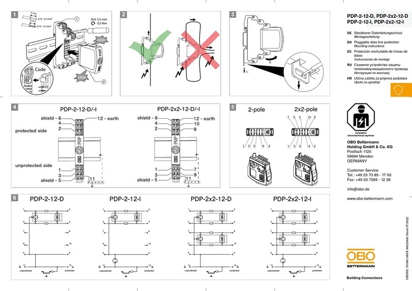
OBO Bettermann PDP-2-12-D User manual

OBO Bettermann
OBO Bettermann PYROPLUG MagicBox User manual

OBO Bettermann
OBO Bettermann PDP-2-5-D User manual