Document UT-MT-0778_EN Page 6 of 39
Edition 11/03/2014 Supersedes edition 02/03/2014
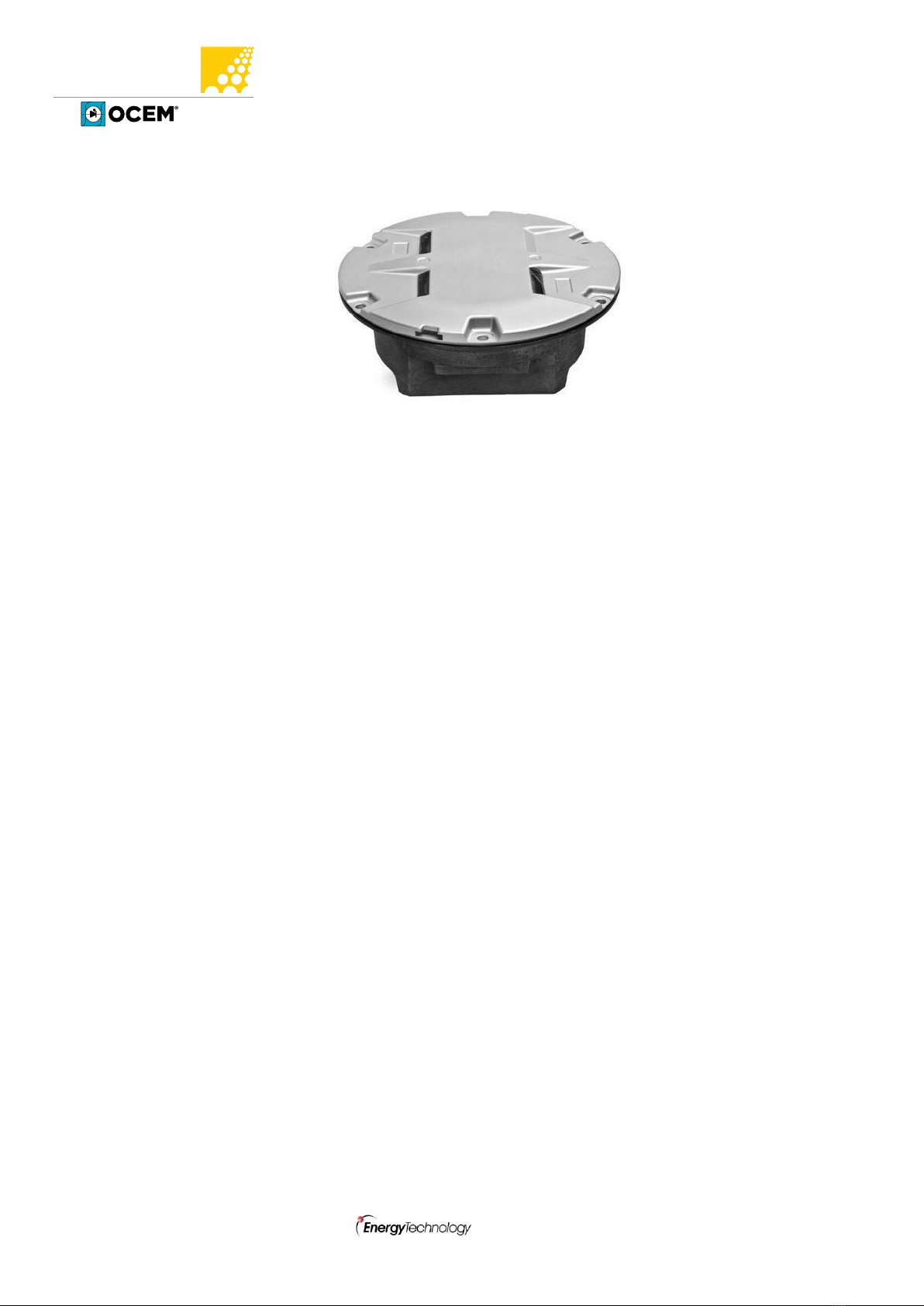
LED INSET THRESHOLD/END LIGHT LTHE04
INSTRUCTION MANUAL FOR USE, INSTALLATION AND MAINTENANCE
4.4 PRISM REPLACEMENT .................................................................................................. 31
4.4.1 Removing the Prism ............................................................................................ 31
4.4.2 Installing the New Prism ..................................................................................... 31
4.5 LED MODULE REPLACEMENT ....................................................................................... 31
4.6 ELECTRONICS REPLACEMENT....................................................................................... 32
4.7 ARCTIC KIT REPLACEMENT ........................................................................................... 33
4.7.1 Thermostat.......................................................................................................... 33
4.7.2 Heater.................................................................................................................. 33
4.8 GASKETS........................................................................................................................ 34
4.8.1 Gasket examination ............................................................................................ 34
4.8.2 O-Ring replacement ............................................................................................ 35
4.9 CABLE LEAD WITH PLUG............................................................................................... 36
4.9.1 Removing the cable lead with plug..................................................................... 36
4.9.2 Installing the new cable lead with plug .............................................................. 36
4.10 PRESSURE VALVE .......................................................................................................... 36
4.11 CLEANING ..................................................................................................................... 37
4.12 MONITORING ............................................................................................................... 37
5TROUBLESHOOTING ..................................................................................................... 38
INDEX OF FIGURES
Figure 1 –8” Dome outside view ...................................................................................................... 9
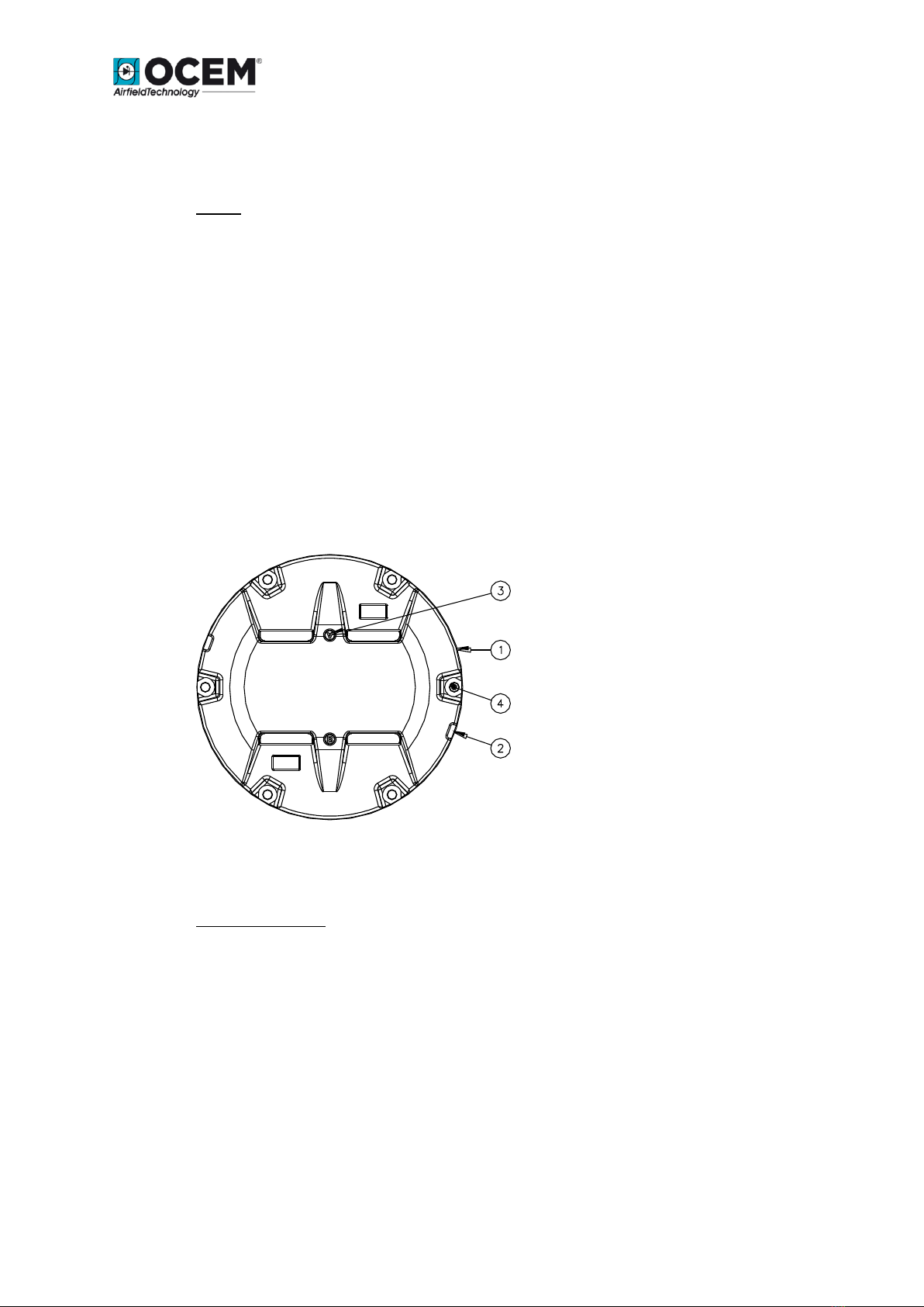
Figure 2 –Lower Cover Outside View ............................................................................................. 11
Figure 3 –Lower Cover Inside View ................................................................................................ 11
Figure 4 –Wiring Diagram............................................................................................................... 12
Figure 5 –Exploded View ................................................................................................................ 13
Figure 6 –Part List........................................................................................................................... 14
Figure 7 - Complete P/N identification............................................................................................ 15
Figure 8 –Standard 12” shallow base............................................................................................. 16
Figure 9 –Pavement Boring, Sawcutting and Joint Intersection Details ........................................ 19
Figure 10 –Example of Light Unit Configuration ............................................................................ 20
Figure 11 –Gaskets for 12” shallow base ....................................................................................... 23
Figure 12 –12” shallow base for side or bottom ducts (method “B”)............................................ 23
Figure 13 –Shallow base installation details .................................................................................. 24
Figure 14 –Optical device (refer to the manual UT-MT-0485 for further information) ................ 24
Figure 15 –Gaskets for L-868 base ................................................................................................. 25
Figure 16 - Lower Cover Fixing Screws ............................................................................................ 29
Figure 17 - Lower Cover with Pressure Valve.................................................................................. 29
Figure 18 –Fixture Gaskets ............................................................................................................. 30
Figure 19 - Prism Cleaning............................................................................................................... 30
Figure 20 - Prism Replacement ....................................................................................................... 31
Figure 21 –LED Module Replacement ............................................................................................ 32
Figure 22 –Wiring diagrams for the heaters .................................................................................. 34
Figure 23–Fixture Gaskets .............................................................................................................. 35